Week 8 embedded programming

Assignments:

Group assignment:

    • Compare the performance and development workflows for different microcontroller families.
    • Document your work (in a group or individually)

Individual assignment:

    • Read the datasheet for the microcontroller you are programming.
    • Design an MCU board using Attiny1614.
    • -Add the essential circuit.
      -Add pin header for GPIOs
      -Add a switch and LED.
    • Program the board to BLINK when the button is pressed using C and Arduino C.
    • Use micropython to program RPI pico.

Learning outcomes:

    • Identify relevant information in a microcontroller datasheet.
    • Implement programming protocols.

Weekly Practices

Research

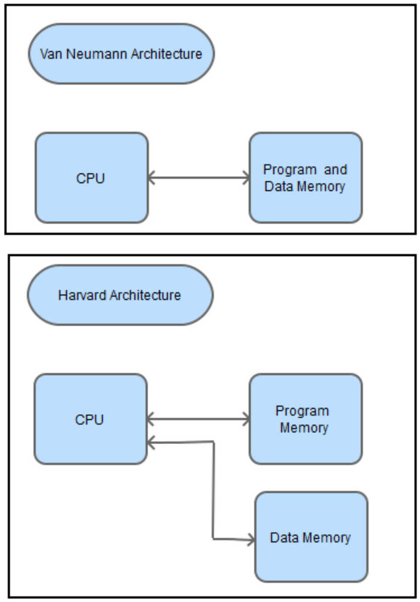
Every computing device falls down under a certain architecture. A computer architecture is concerned with the organization of the logical components that make up a system. A computer architecture is implemented to execute a certain set of instructions like arithmetic operations and memory access. These instructions which are executable by an architecture are called Instruction Set Architecture (ISA). There are two main types of architecture: Von Neumann and Harvard architecture.
In the Von Neuman architecture the CPU executes instructions written in the main memory and also stores variables in the main memory. The CPU can access input/output devices connected to the bus.
In the Harvard architecture, the CPU reads instructions from the program memory and stores variables in another memory.
To my knowledge the main difference between them is that memory can only be accessed once per clock cycle, in principle a Von Neumann architecture requires at least two clock cycles to execute an instruction, whereas a Harvard architecture can execute instructions in a single cycle. Thanks to my instructor who guided me to this useful link .

image
image

Programming in C

I learned a new coding language and practiced it on microchip studio and tried to use its tool chain but the arduino plugin had an error that did not find the source arduino file. For learning the C programming language I followed these 2 links. tutorial and arduino guide

image

Weekly assignments Group assignment

Here is the link to the group assignment page.
This week’s group assignment was to compare the performance and development workflows for different microcontroller families, by using an oscilloscope to measure their frequency with a simple source code, blinking a led without any delay in 2 languages C and arduino C. Attiny44 and Attiny1614 were used and also RaspberryPi Pico by python to compare between all.

image image
image

Here are the MCU with the language type results:

    1. Attiny 1614 with C = 2.865MHZ.
    2. Attiny 1614 with arduino c = 756.750KHZ.
    3. Attiny44 with C = 2.478MHZ.
    4. Attiny44 with arduino c = 185.29KHZ.
    5. RaspberryPi Pico with python = 57.220KHZ.

It is observed that if the instructions are specified to the registers directly it takes less time than the arduino language takes more time to translate it and then execute it. As for the python, the lowest frequency indicates taking very much time while executing an instruction.

image

Individual assignments

Datasheet

For this week’s assignment I read the data sheet of attiny44 and attiny1614 , specially the pin configuration part to understand its functionality. So first we understand what a data sheet is.
From Wikipedia: datasheet, data sheet, or spec sheet is a document that summarizes the performance and other technical characteristics of a product, machine, component (e.g., an electronic component), material, a subsystem (e.g., a power supply) or software in sufficient detail to be used by a design engineer to integrate the component into a system. Typically, a datasheet is created by the component/subsystem/software manufacturer and begins with an introductory page describing the rest of the document, followed by listings of specific characteristics, with further information on the connectivity of the devices. In cases where there is relevant source code to include, it is usually attached near the end of the document or separated into another file.
First page of every datasheet is based on key features, it is like a review page which describes whether a device is useful for specific work or not. Also I learned that I could search for what I need to do , and which register to write in .For example, to program a certain pin as input , I need to write 0 in the specified register in the bit corresponding to the pin number .Also through the datasheet , I found the pins’ names to be used in Arduino IDE. further explanation will be explained in the assignment below.

Design/Fabricate/Program a new MCU.

This week’s assignment was to fabricate a new MCU using attiny1614. To do that I first checked the needed components to make a hello echo world using attiny1614 through this link .
For the first time in my life I fabricated a pcb board with a common ground feature. It is easy to do in the designing stage but the fabrication process it was a new thing for me.
My focus in this documentation will be on the programming stage that is why some initial stages will be described generally.

image
image

And added GPIO’s pinders and a switch with LED’s in the Kicad designing process. To view in more details kindly visit week4 for how to design a pcb in the Kicad software.

image image
image image

Then I fabricated in the lab. Due to common ground feature the process had a different result this week, while preparing file for fabrication the rule of the traces layer is that to keep the traces white and the CAM software will detect the black color and cut on it, so when the fill option is done on GIMP due to the openings of the common ground, the pads also disappear so I kept it unfilled so it also traced on the ouline also, which added time in the fabrication process. For me it didn’t really matter as I always wanted to try that that is why I carried on fabricating this way. For more details on fabricating the pcb kindly visit week4 and week6.
I used the Mods as my CAM software for the Roland mdx-20 machine.

image image
image

After fabricating successfully I started soldering it. This time I felt that it took less time than what I expected in soldering my new PCB .It may be because of the practice.
After soldering I realized that I had made a silly mistake in my design which I have mentioned in the challenges section.

image
image

Then I started the main part which is programming my board. I first went to the programing instructions on how to program it by visiting week4 and this website Which helped to do it all on my own.
Also referred to the data sheet for the pinout configuration for attiny1614 .
As to clear the doubt for the Arduino pin configuration from this link I found the first photo very useful and self explanatory.
For C programming pinout, I also found this useful document which mentioned all configurations in more detail than in the datasheet.

image
image

I started by connecting my new board to the programmer, since I had fabricated 2 boards in week4 for the updi programming I used them this time, 1) FTDI-usb board 2) UPDI-serial bridge.
I connected the first one in my laptop and the other to the first one with the female - male FTDI pin headers. And from the bridge to the new board I used the jumper wires to connect to the UPDI pin, GND pin and VCC pin. (as shown in the picture).

Then by the reference above I first wrote my code in Arduino C. so that I know that all works well and I had confidence that if there is a problem then it is not in the code :)
My 3 led’s were situated on pins 0, 2, and 10. And the switch on pin 6.
The summary of my source code is:

    1. I defined the pins by using #define command on the top.
    2. In the void setup: I had set the pins output or input by using pinMode() command and added pullup for the input switch by using INPUT_PULLUP command.
    3. In the voip loop : I created an “if” statement that indicates if the switch is pressed (read- digitalRead() ) turn on the leds (digitalWrite()) and if not then keep them off by using the same command and indicating it LOW.

Then when it practically worked, then only I began to write in C. which summarized the same instructions but different commands.
- PORTx.DIR data direction register. (equivalent to pinMode).
- PORTx.OUT pin configuration equivalent to digital write.
- PORTx.IN pin configuration equivalent to digital read.
- PORTx.PINnCTRL to enable pullup configuration on that specific pin.
And voila here are both source codes, the files will be found down on the bottom of the documentation.

image image
image

After fabricating and before uploading the code I had to first burn the bootloader on it, I used the Arduino toolchain to burn the bootloader by following the programming instructions which was stated above. In the tools options I selected attiny1614 in the boards and UPDI - slow in the programmer and checked in the port that the generic D11C14A is detected and then finally clicked on the “Burn Bootloader” option.
Hooray it was a success in my first attempt, I was very relieved that my pcb is working fine and successfully burned the bootloader on it.
As for the source code sketch. After writing the code and compiling the sketch to verify it without any errors, I kept the options in the tools tab and selected “Upload using programmer” from the sketch tab. And voila it was a successful attempt.

image
image image

Here are the hero shot and videos.

image

I also practiced on my other board fabISP arduino tool chain as well as the make terminal toolchain while learning programming in C.
As mentioned in week4, I first copied from the Prof Neil make file and saved it in a new text/ notepad++ file with the same extension .c.make
Then I also created a new file and pasted in it my C code and saved it as .c extension.
In the end, I opened gitbash and started following this commands make fuse then make program.....
It looks simple when all works out very well but the preparation and any miscalculated error gets very painful :)
As for the arduino tool chain for the fabISP, as described above with UPDI programer but only difference is the tools options which is shown in the picture below.

image image

RaspberryPi Pico

For this week’s assignment also I had to explore another language called python language on RaspberryPi Pico. and use a new live tool called micropython which allows live communication while coding, so as a user interface and coding it is very cool but as a usage I haven't used it that much and I am used to arduino so that it why I am more comfortable with what I am used to.
I followed this tutorial to learn basic coding and blinked the led on RaspberryPi Pico.
Here are the hero shots and a video.

image image

Voila its done

To sum up, I completed the following:

    • √ Linked to the group assignment page.
    • √ Documented what you learned from reading a microcontroller datasheet.
    • √ Programmed your board.
    • √ Described the programming process/es you used.
    • √ Included your source code.
    • √ Included a short ‘hero video’ of your board.

File: Kicad design file + source code files c and arduino c.

image

While programming a new error was a success for the previous one :)

#Challenges 1

There was a very silly pcb design mistake that my new board did not fit in the programmer due as shown in the picture.

#Solution 1

I realized this problem after soldering it so that is why I had to return to the jumper wires to save the day :)

image

Aknowledgment

    • √ Special Thanks to all the links stated in my documentation above which I referred and learned from them.