Week 15 Interface and Application Programming

Assignments:

Group assignment:

    • Compare as many tool options as possible.

Individual assignment:

    • Write an application that interfaces a user with an input and/or output device that you made.

Learning outcomes:

    • Interpret and implement design and programming protocols to create a Graphic User Interface (GUI).

Weekly Assignmnets

Group Assignmnet

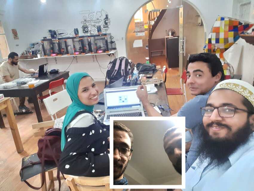
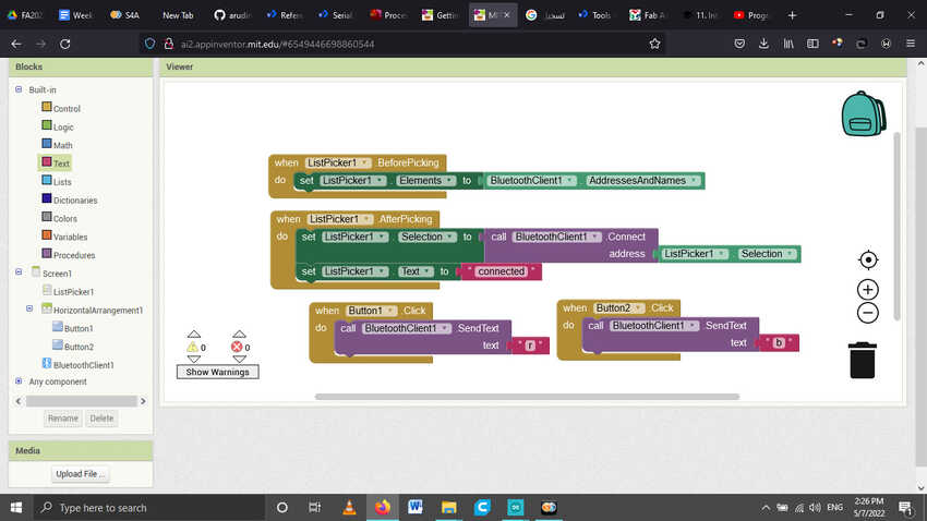
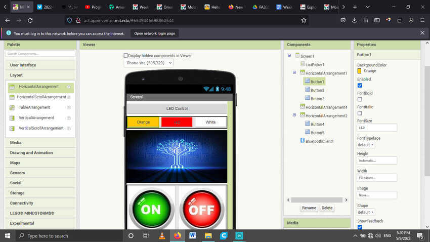
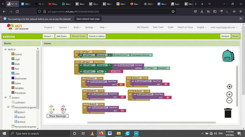
This week’s group assignment was to use and compare as many tools as possible. Thus, we chose to explore three different types of applications. Processing, Scratch and MIT inventor app.
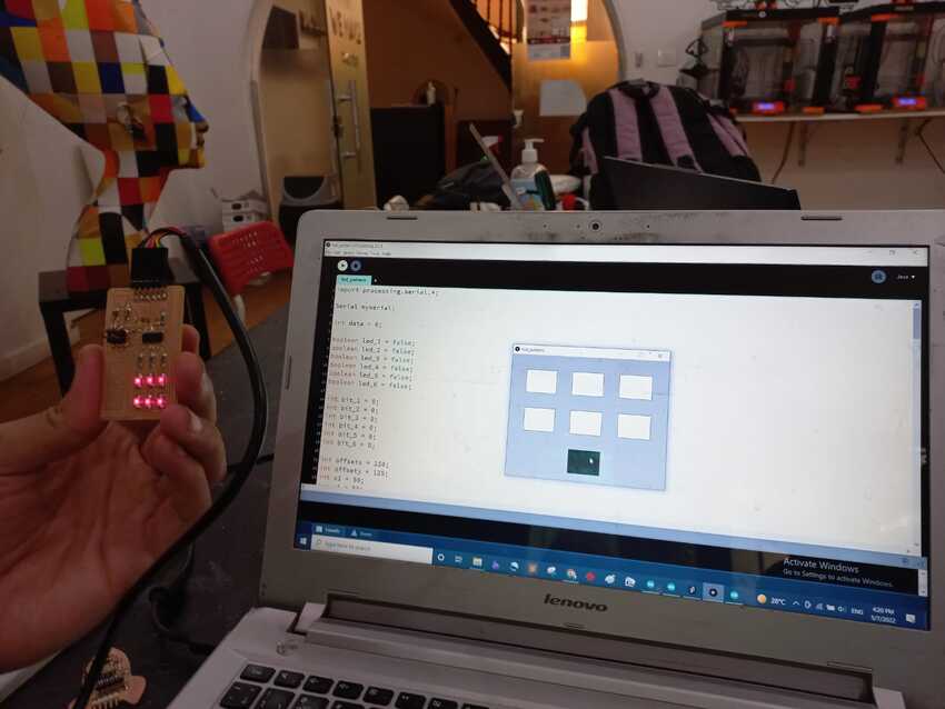
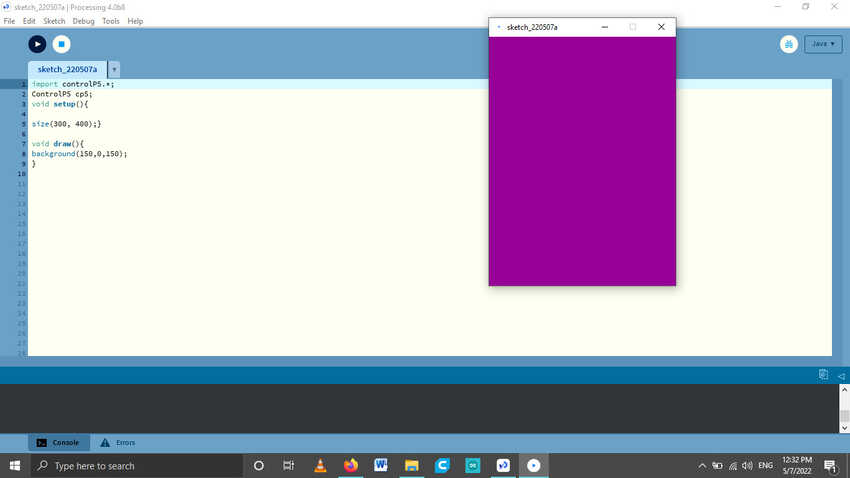
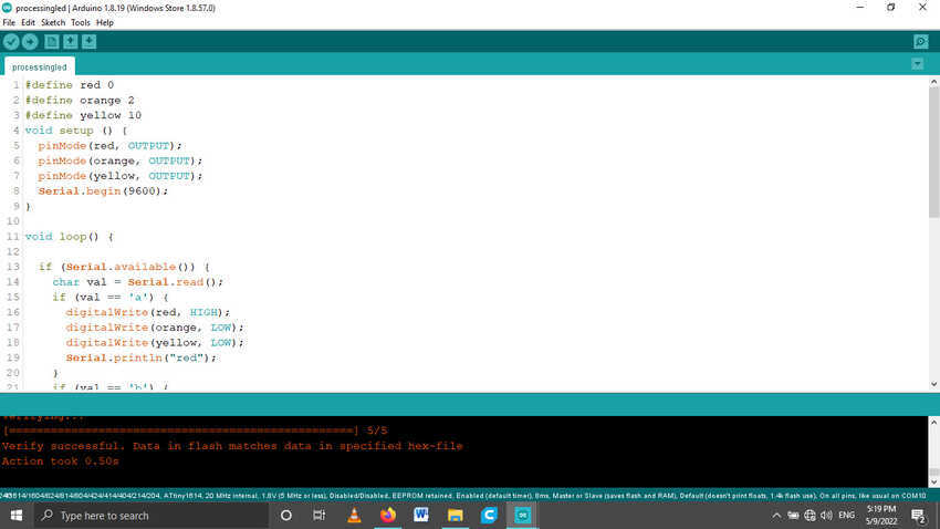
Our instructor had prepared a PCB for us containing 6 LEDs with Charlieplexing code and processing GUI code. The GUI code was the same one used when we were in bootcamp before joining fab academy, by observing the teacher’s display we finally learnt how he wrote it and what each code was talking about. The underlying part of this session was that the buttons were written from scratch excluding the usage of the P5 control library. For beginners like me this was a eureka moment for us.
The source code and other information will be found in my bootcamp website .

image image
image

Processing: My role in the group assignment and kind of practice of many tools all by myself. I started with the processing. It is an IDE for visual arts using coding. The language is simple. I downloaded the controlP5 library to make it easier, and to build my GUI application then interface with my electronics using Serial communication. A show of gratitude towards our instructors for equipping us with valuable resources and valid examples, it proved to be a major helping hand in our research and smoothed over any further bumps. They provided with documentation and examples .
I started with small steps and then tried a little demo with arduino uno using a simple LED turn on and off button code to familiarize myself with this tool. I referred to Waleed’s documentation while exploring the tool as it was easily understandable for me.
Here is the video

image

MIT App Inventor: I moved on to explore the second option MIT App Inventor which I found the most interesting and applicable out of the three options that we had chosen. As It allows us to build applications for Android. So I tested it by using it to build applications on my phone which can also interface with other electronics via bluetooth module HC-05. The module itself communicates with any PCB via serial UART protocol TX and RX.
The web client is also user friendly, the video tutorials are also informative and helpful. For exploring this tool I followed this video for making simple GUI app with three buttons.

    1. To connect with the bluetooth.
    2. To turn the LED on.
    3. To turn the LED off.

The coding also is very simple, similarly like the tinkercad code blocks, it contains many features to add on.
This is one of the reasons why I chose to further pursue exploring this tool for my individual assignment.

Scratch: This third choice of ours is a unique, very nice tool which communicates live with the arduino board. All users could use block programming to program and interface with their electronics. Thus enabling them to build a scratch program on their computers and use serial communication for manipulating pins on the motherboard.
I started with this tutorial to make a simple connection. Then paired with Amany, we further explored without any tutorials using RGB LED to play with this tool.

Reflection after using three different tool options for interfacing are as follow:

    • Processing: Very Interesting and vast according to creativity but limited to wired laptop connection.
    • MIT App Inventor: simple and easy, limited to code blocks but could connect wirelessly through mobile phone.
    • Scratch: new and useful while learning code blocks but it is limited to arduino boards only.

Individual Assignmnet

This week’s individual assignment was to write an application that interfaces a user with an input and/or output device that you made. I used my 1614 board which I previously fabricated. Due to time constraints, I couldn’t fabricate a new pcb board. I began with the arduino code and added more buttons on on the group assignment / practice code and changed the commands for each button as follow:

    1. To turn on only orange coloured LED and turn everything else off.
    2. To turn on only red coloured LED and turn everything else off.
    3. To turn on only white coloured LED and turn everything else off.
    4. To turn the 3 LEDs on.
    5. To turn the 3 LEDs off.

Giving each a character from “a” to “e” for serial communication.
Here is the code

Arduino file
image

Then I visited the web client MIT App Inventor, and started with adding first the interface buttons then its backend.I began with the bluetooth connection button and kept its width fill parent. Then I added a horizontal arrangement- in which I added 3 LEDs buttons orange, red and white. And filled each with their own color and aligned them equally as per their width to fit the parent/ window of the user. Then I wanted to insert an image for aesthetic view so I added another horizontal arrangement- changed its height to increase by 40% and then clicked on insert image. I had saved an electronic networking type image from before for the academy website so I used it to reference the interfacing connection between the PCB and the mobile phone. Then last but not the least, I added another horizontal arrangement- to add 2 buttons for all on/ off commands for LEDs. This time I inserted ON and OFF images on the buttons to experiment with the new image pressing button feature.
Voila the interfacing is done. And looks like this.

image

Now for the backend part, programming the interface. As mentioned above I used the bluetooth connection code as the tutorial had shown. With the conditions of before connecting and after connecting changes. When the mobile gets connected to the bluetooth module it changes its text to “connected”.
Then for the rest of the buttons, It is a simple code block that if the button is pressed it sends a signal via bluetooth defined character “a” to “e” for each button. And fulfill the arduino code as it receives that character.
Here is the full code.

image

Then I connected to Ai companion app via QR code and then connected it with bluetooth. Voila it's all done
Here is the video.

image

Voila its done

To sum up, I completed the following:

    • √ Linked to the group assignment page.
    • √ Documented your process.
    • √ Explained the UI that you made and how you did it.
    • √ Outlined problems and how you fixed them.
    • √ Included original code (or a screenshot of the app code if that's not possible).
    • √ Included a ‘hero shot/video’ of your application running with your board.

#Challenges 1

This time I faced a different type of issue/ challenge “time constraint”. That is why I was able to do simple things this week as compared to other week’s.

#Solution 1

I decided to get back to this week in the coming week for further exploration.

Aknowledgment