
Week 13
Networking & Communications
-
Group Assignment
- Send a message between two projects Individual Assignment
- Design, build, and connect wired or wireless node(s) with network or bus addresses
Group Assignment
In this week's group assignment we wanted to send a signal between 2 projects, so I connected an Attiny44board I made in an earlier week as a Master an Attiny1614 as a Slave. We decided to use the UART which stands for Universal Asynchronous Receiver/Transmitter.
So in this type of connection all we need to connect is 2 pins in each microcontroller, the TX & RX pins. And as shown below.
TX/RX pins in Attiny44
We just had to make sure that Attiny1614 has a UART connection. And after looking in the Datasheet we found that it supports the UART connection, and all we needed was to find the pinouts of TX & RX.
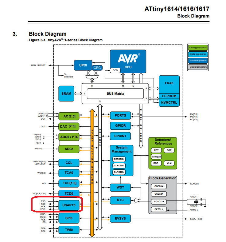
Attiny1614 Block diagram
Thanks to Christopher that he shared the pinout of the Attiny1614 and we found that:
- PB3/pin6 - RX
- PB2/pin7 - TX
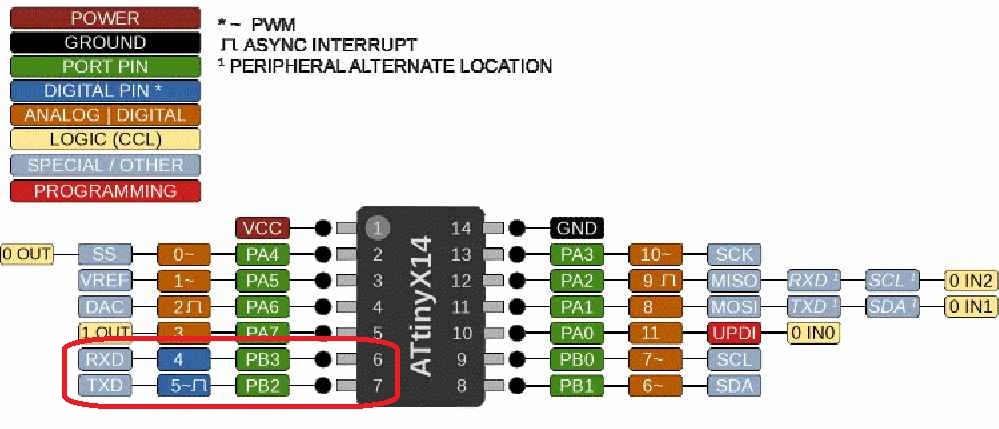
Attiny1614 Pinout
The most important point in this connection is that we need to connect the RX in one of them to the TX of the other board and vice versa, as following.
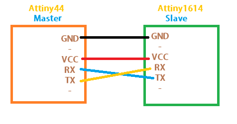
UART connection
So as Attiny44 does not support the TX/RX we needed to add that to the code so it can read and write from those ports. So we had to get Neil's code for hello echo attiny44 that allows this microcontroller to send and receive data through UART. And we just edited the while loop to fit our purpose which is defining the Push button as input at pin 7. and let it read this pin when pushed.
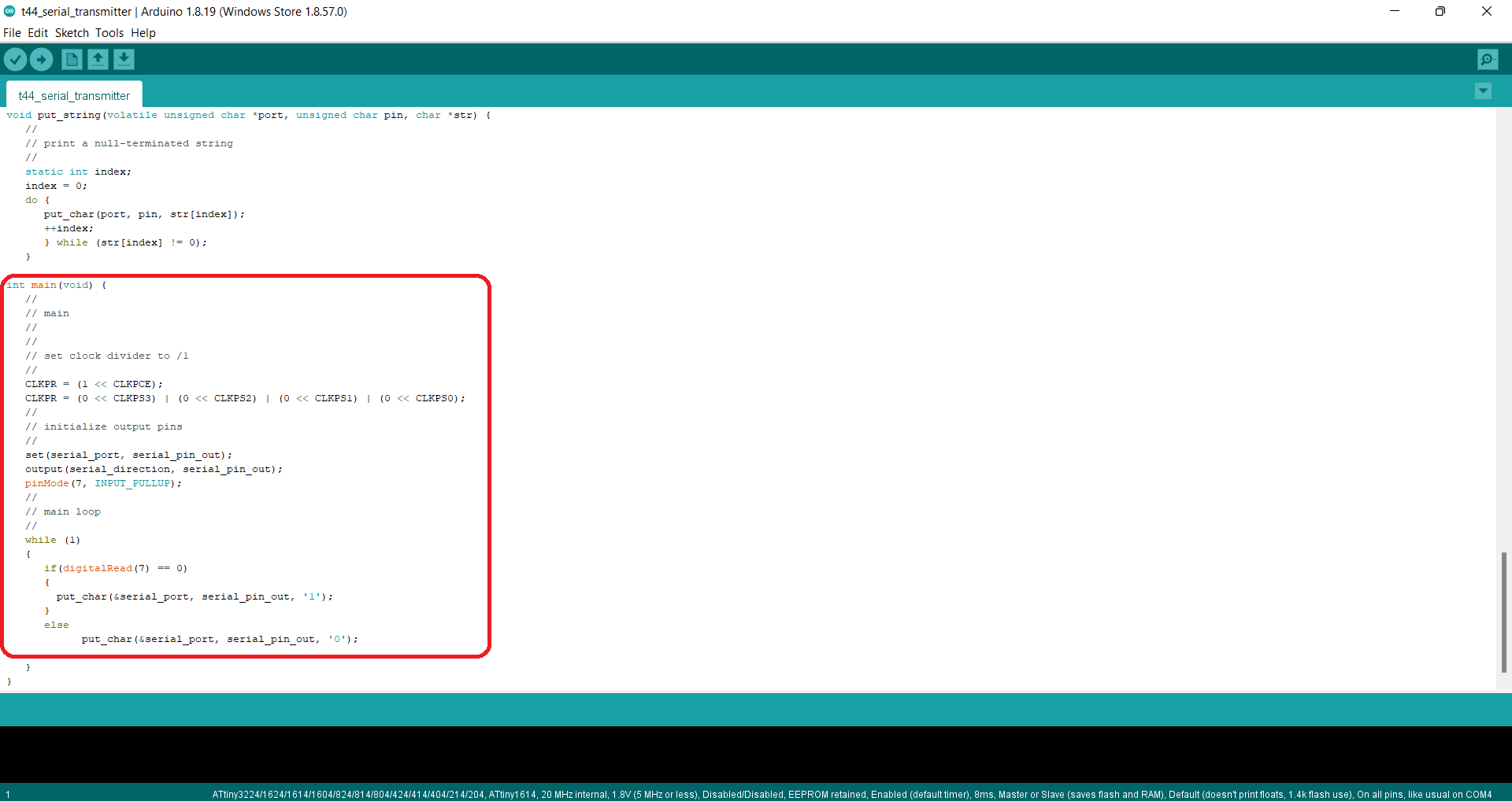
UART master code for Attiny44
And for the Slave code I have written this simple code that defines the LED at pin 8 and just waits for the push button to be pushed on the master's board to be On.
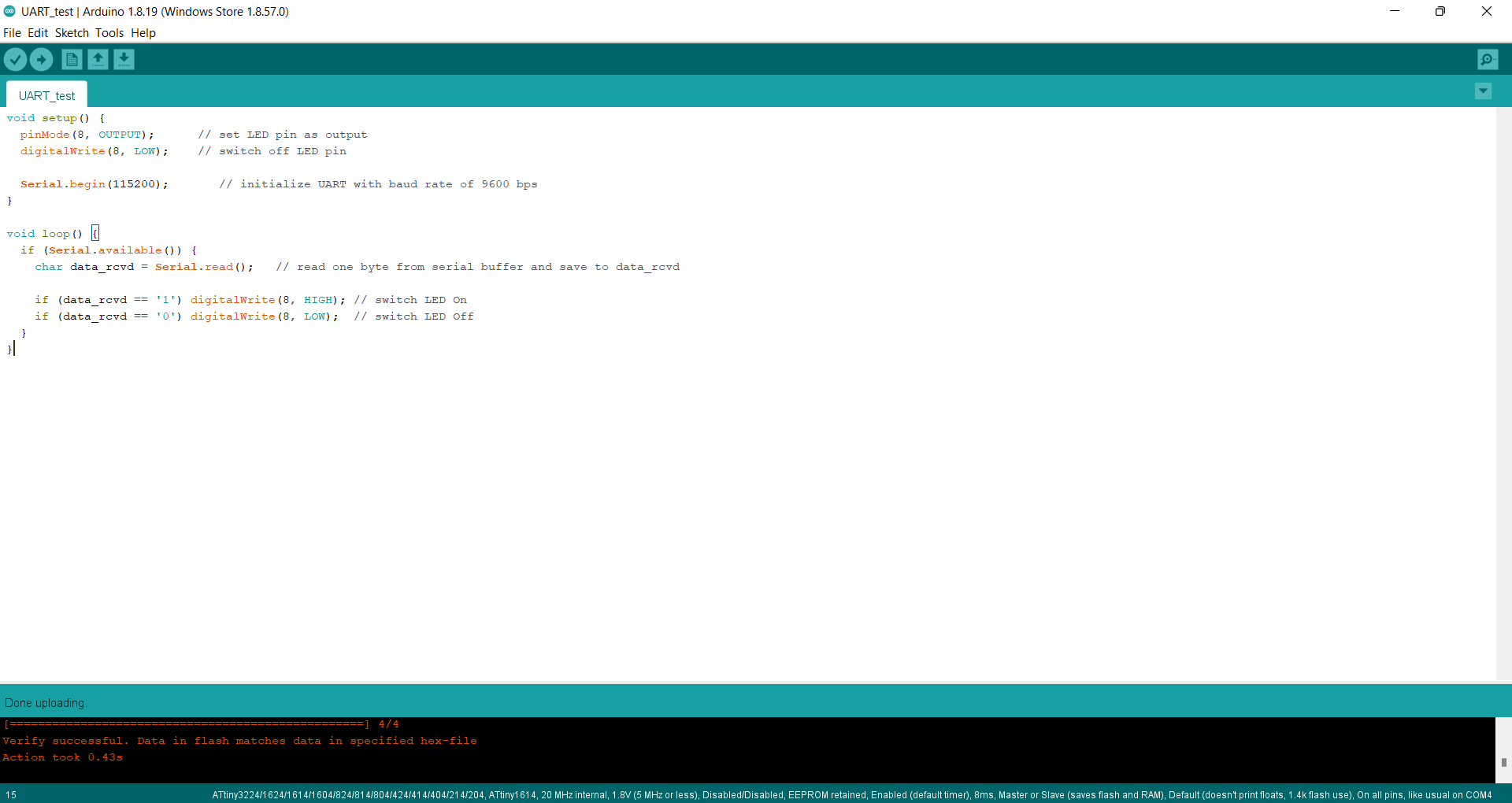
UART slave code for Attiny1614
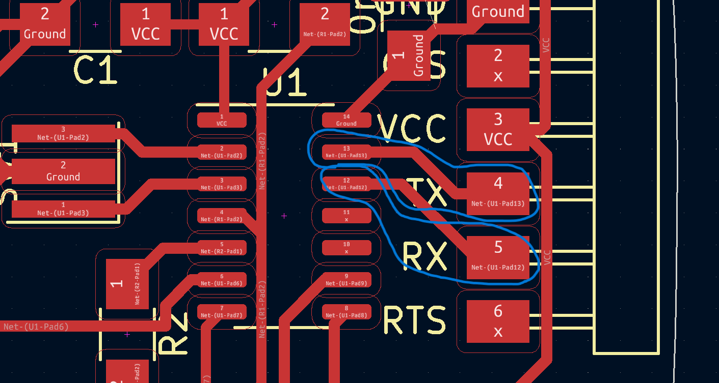
And this was the output. and as shown the 5V power source was taken from the FabISP programmer as I needed the FTDI pinouts to connects the 2 boards together.
UART master/slave connection
Individual Assignment
In this assignment, I wanted to try using the I2C connection protocol using Attiny44 as master and slave. I have seen that the Attiny44 supports the Two-wire mode operation as mentioned in the Datasheet
All it requires is the SCL (Serial Clock) – The line that carries the clock signal and the SDA (Serial Data) – The line for the master and slave to send and receive data.
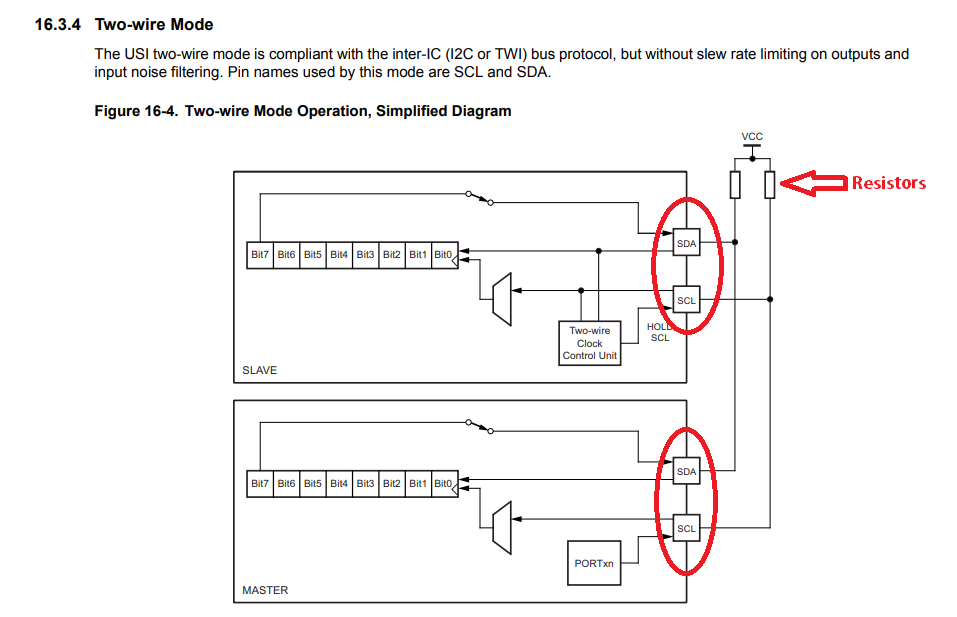
Two-wire connection Attiny44
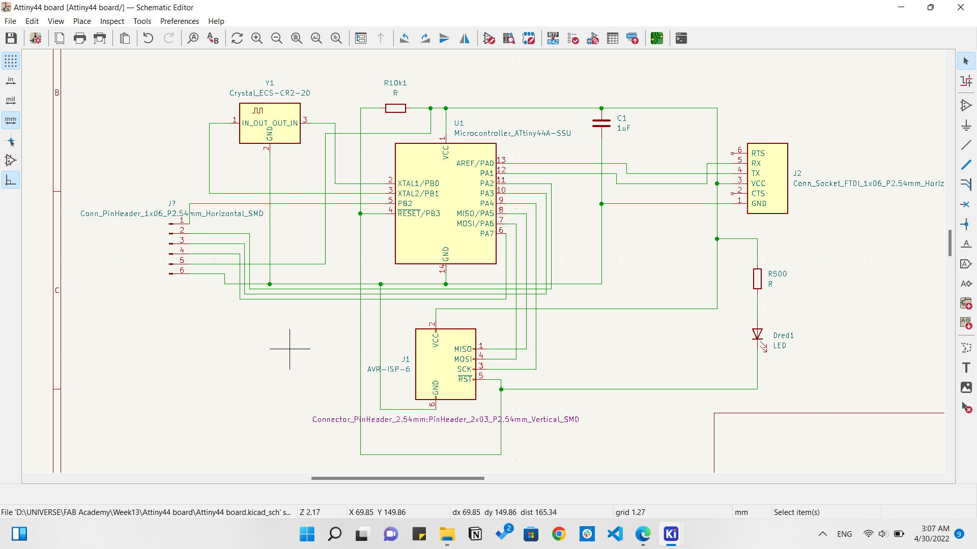
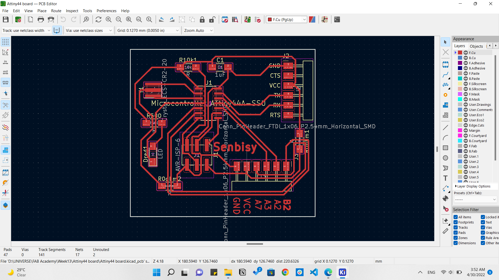
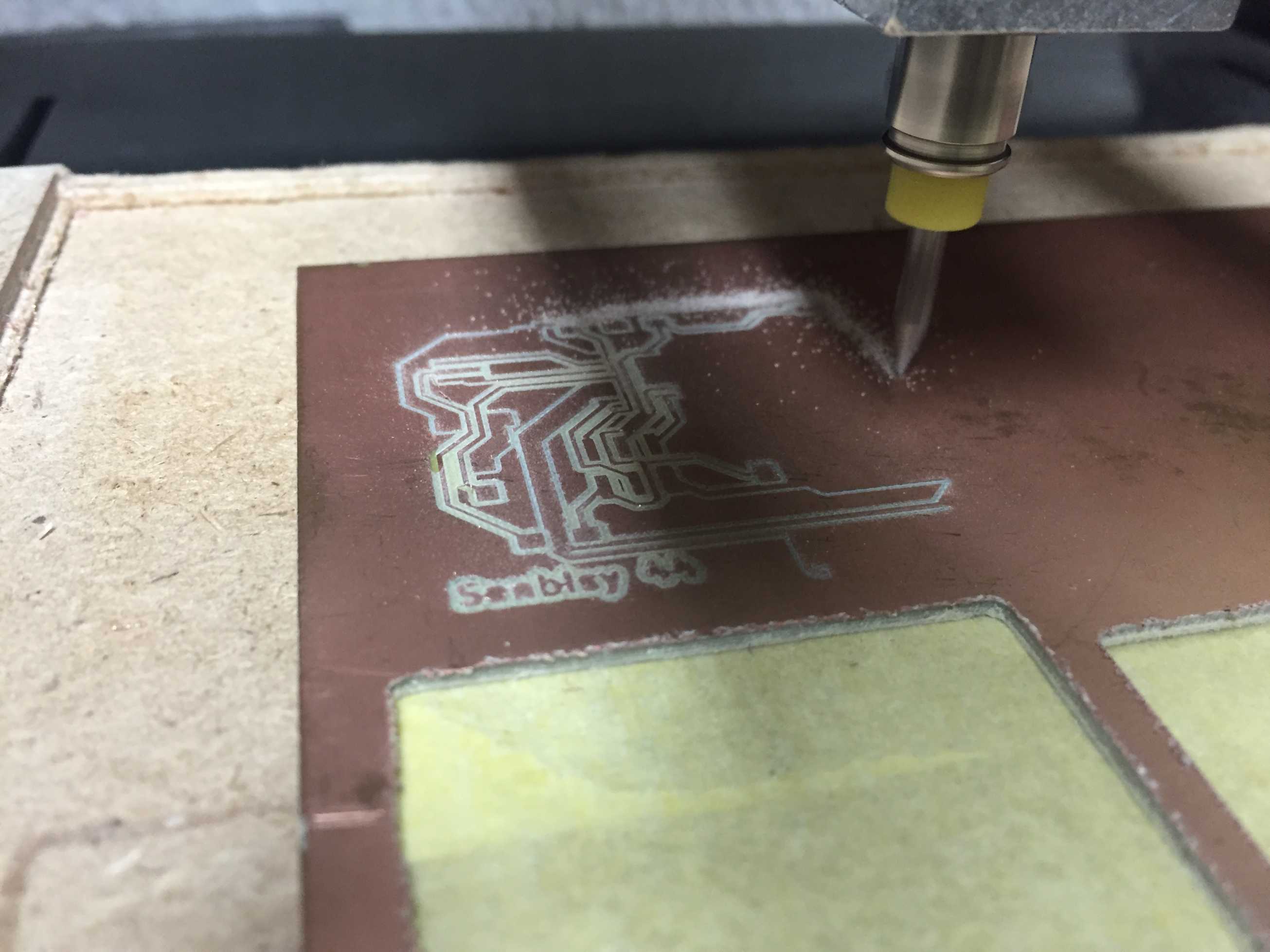
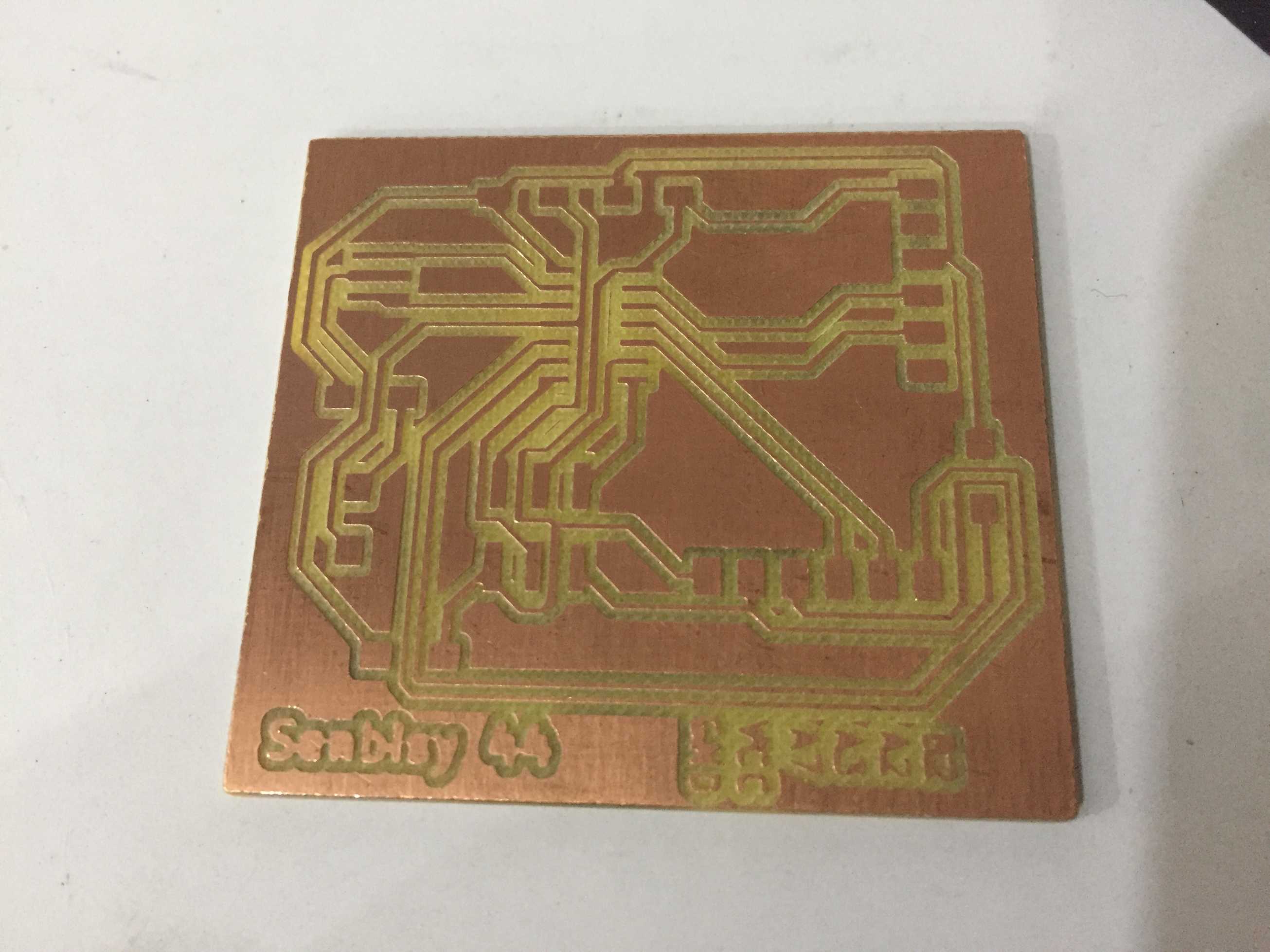
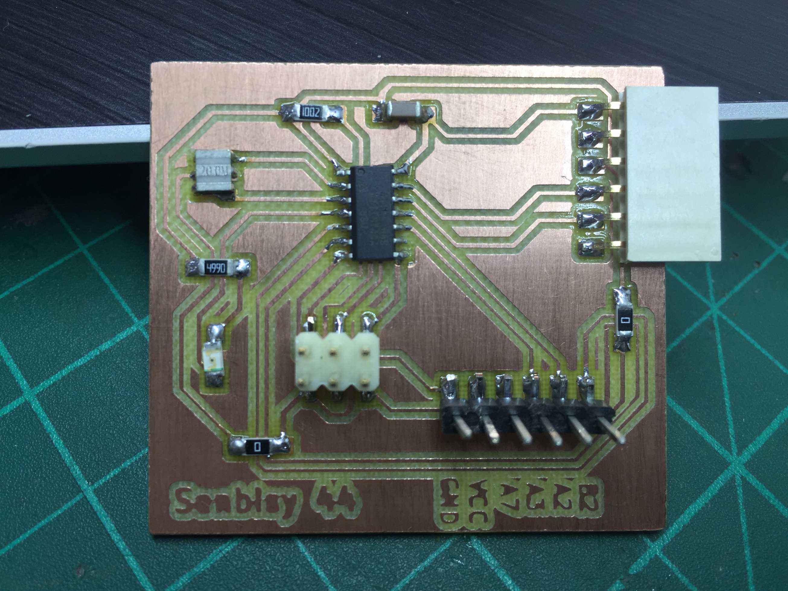
I just needed to make another Attiny44 board as I had only one made in an earlier week and it had no GPIO pins. So I designed it as shown below.
Then I've seen that Duaa has typed a code using Wire library that works with Attiny series. And it seems to be working perfectly with her. So I tried to use those codes but unfortunately they didn't work with me.
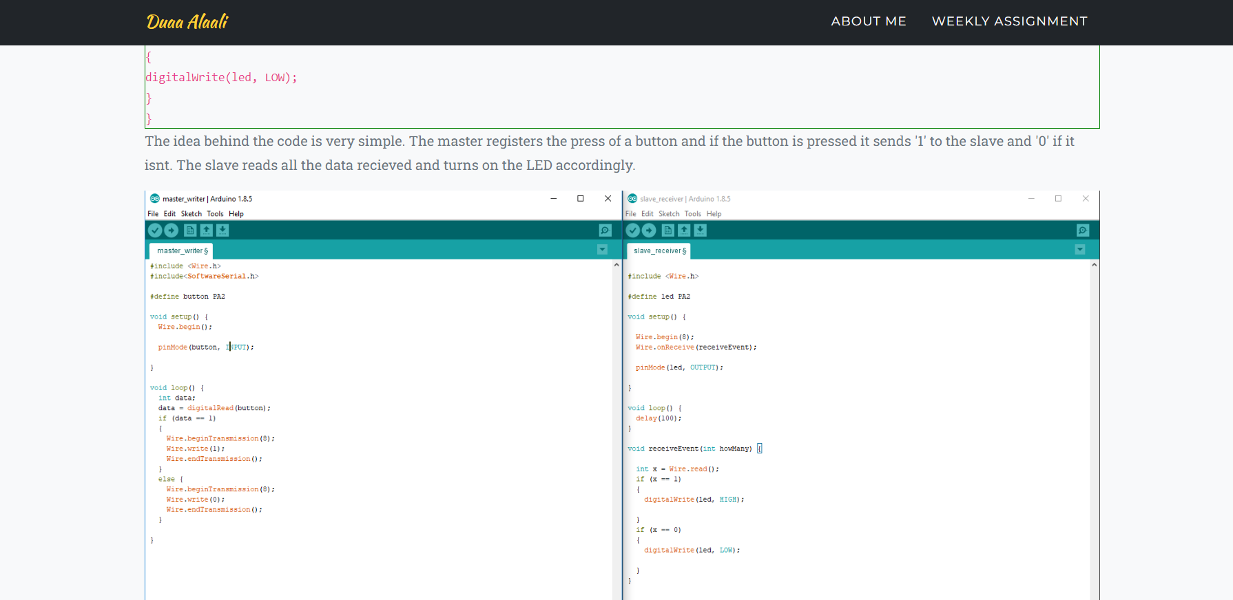
Duaa's Master & Slave codes
So I had to see something else and I found that Alvaro has used Attiny44 too but this time using TinyWireM library for the master code, and TinyWireS library for the slave code.
So I started making the connection as following.
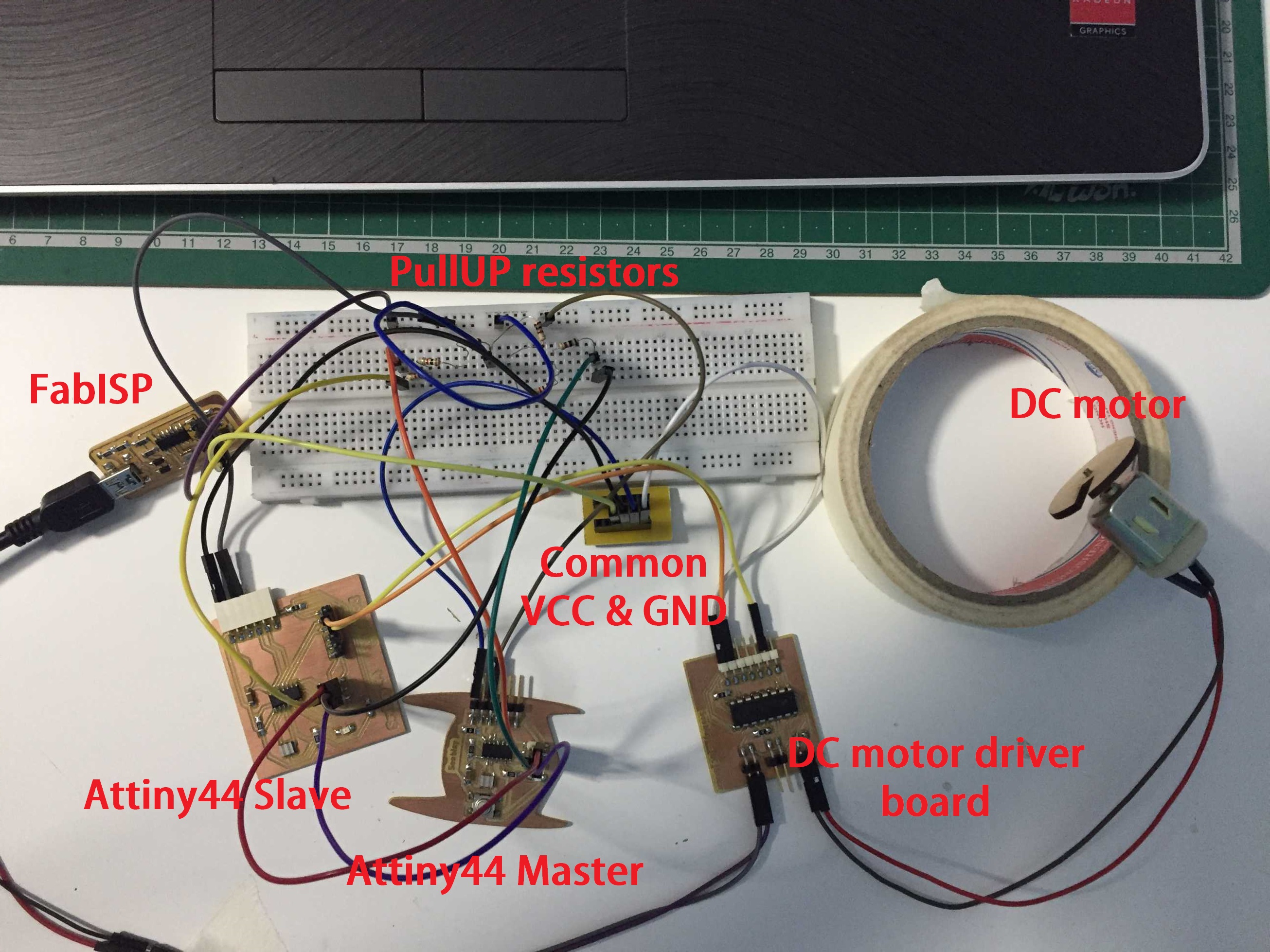
I2C connection
That didn't work too! as I kept pressing the button and nothing happened.
I2C not working
Finally I found that I should use libraries as following:
- TinyWireS.h - Attiny44 as Slave
- Wire.h - Attiny1614 as Master
So I installed those libraries to Arduino IDE.
Master code
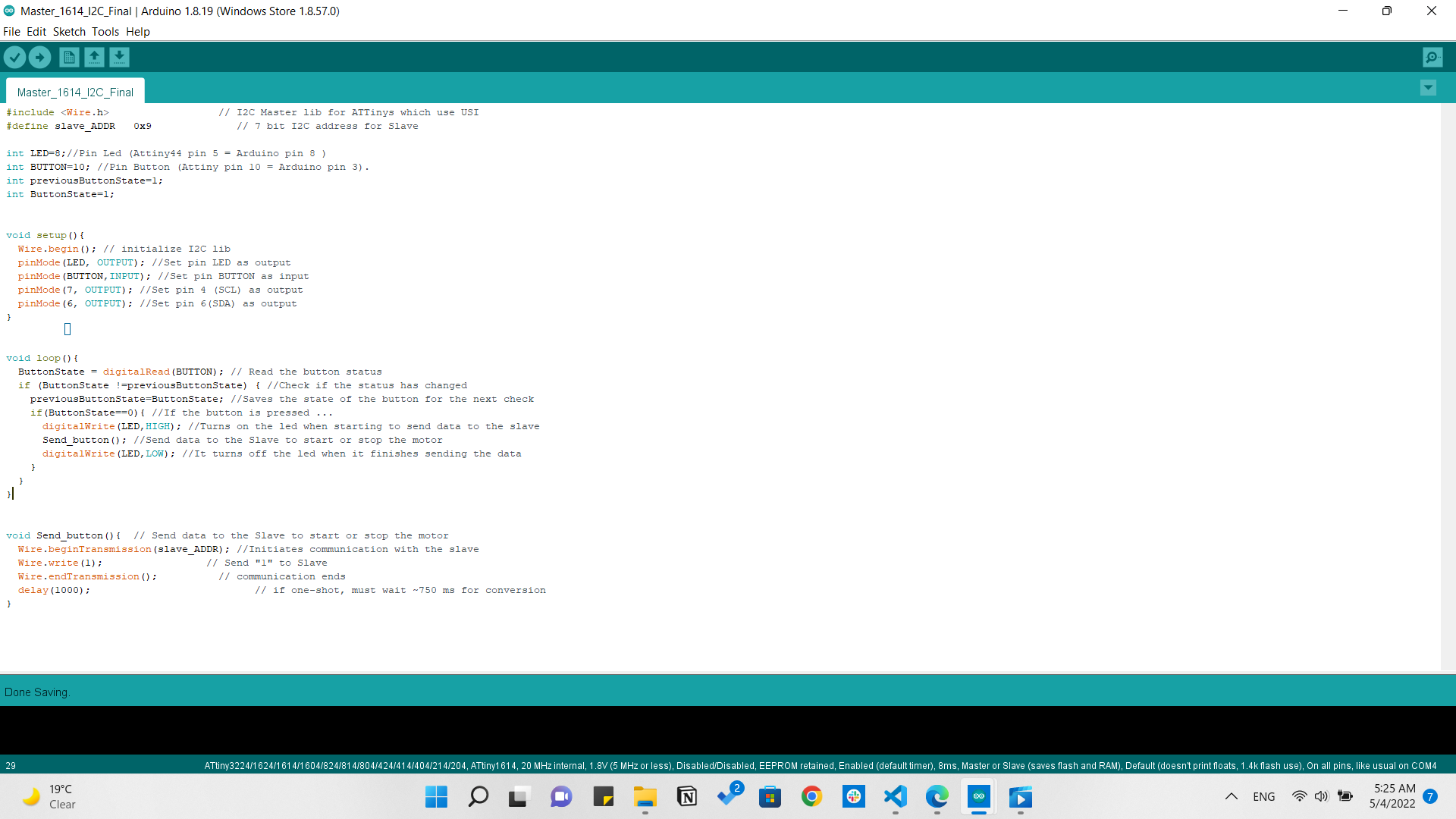
I2C Master
Slave code
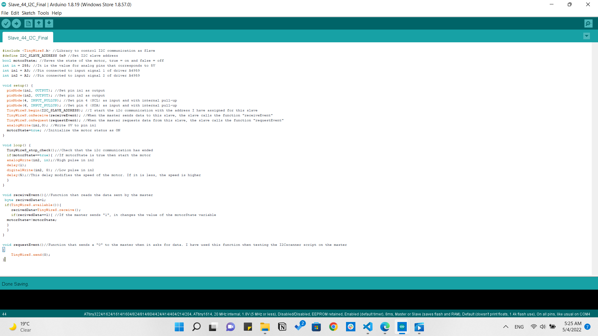
I2C Slave
This code was made to operate the DC motor and when the button is pressed it keeps the state of the motor as it is either rotating or stopping.
I2C Master & Slave
Downloads
Master At44 UART code Slave At1614 UART code Master At1614 I2C code Slave At44 I2C code