Week 13 Input devices

Assignments:

Group assignment:

    • Probe an input device(s)'s analog and digital signals.
    • Document your work (in a group or individually)

Individual assignment:

    • Measure something: add a sensor to a microcontroller board that you have designed and read it.

Learning outcomes:

    • Demonstrate workflows used in sensing something with input device(s) and MCU board.

Weekly Practice

This week I practiced by creating capacitive touch sensor which allowed me to have good sense in this week's content. I followed these 2 links to get the basic information I needed. link1 / link2 .
N then I wrote a simple tactical switch type code in arduino IDE. if the circuit is closed by two separate copper sheets if touches together the led turns on.
I first tried it with arduino and external led
Then I shifted to my attiny1614 pcb which I had fabricated in week8 which had gpios, so I was able to connect to any input devices easily.
Here are is the video.

Arduino file
image
image

Practice for capacitive touch sensor was done by refering to Roberthart documentation and using his first code.
I used the same board attiny1614 and uploaded the code using arduino IDE , I had to change input pin no. as attiny1614 does not have pin A0 so I changed it to pin number 10 as it is PWM analog pin. After uploading the code I connected my board serial FTDI to view the results on arduino serial moniter.
here is the video.

image

Weekly Assignmnets

Group Assignment

Our Instructor had demonstrated the change of an analog reading affect the voltage signal in an input device (temperature sensor board) using Neil's code. The bservation: 1) seen via GUI of the temperature reading.

image
image

2) We also measured the output signal from the sensor so when the temperature went up the voltage went down and vice versa..

image

We also probed on oscilloscope the ldr module which had analog and digital reading so we tested both of them to see the difference
As seen in the above video square wave length is seen as it is digital reading 0 or 1 .
As we expose the sensor with light the volts decreases due to resistance. And returns complete 5 volts as we turn off the light.
The video below is the example of Analog reading in which the syn wave moves according to the brightness of the light.

image

Individual Assignmnet

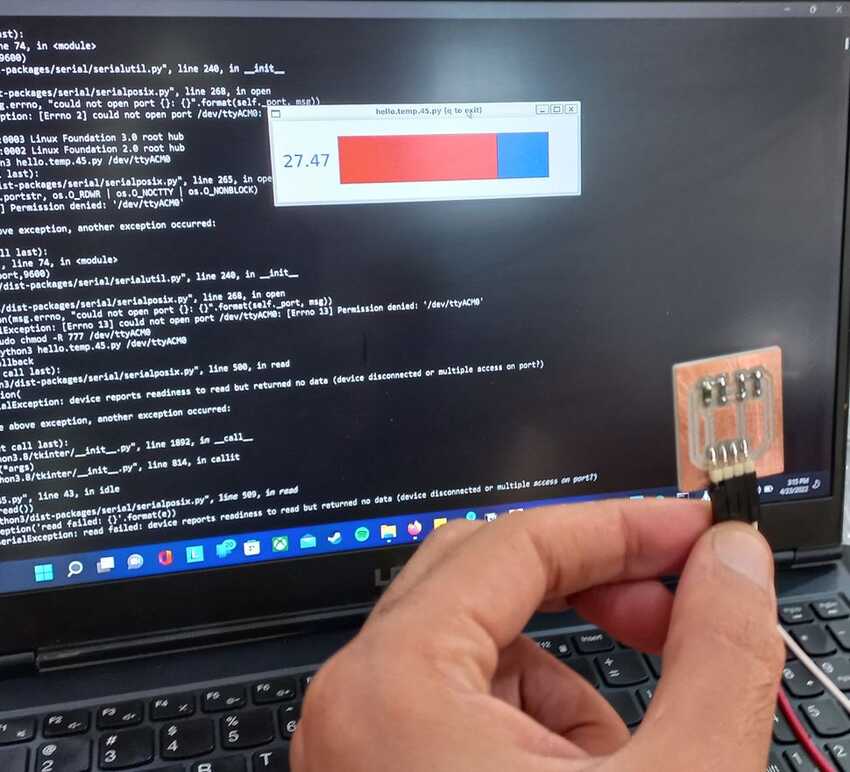
As for my individual assignment since I didn't have time to fabricate a new PCB I used my attiny 44 board (which I had fabricated in week6) and fused on it hello world sc04 file and get input : measure distance of any object and display it on serial monitor of arduino IDE. (but could not finish it)
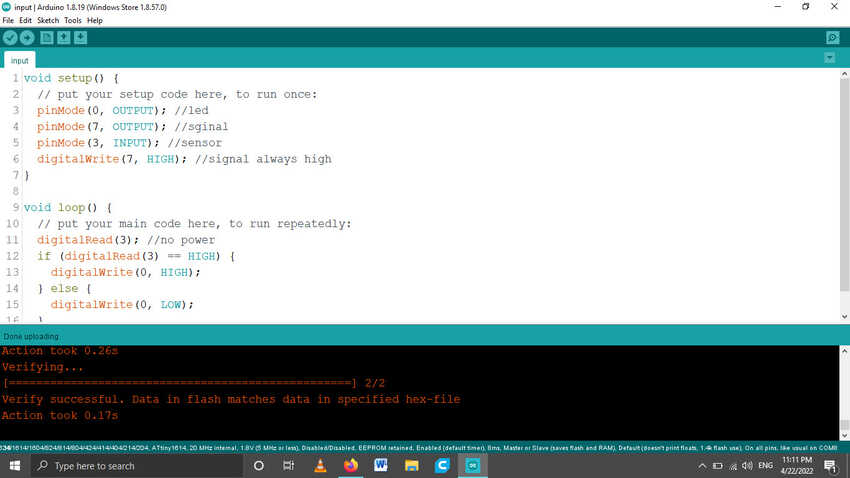
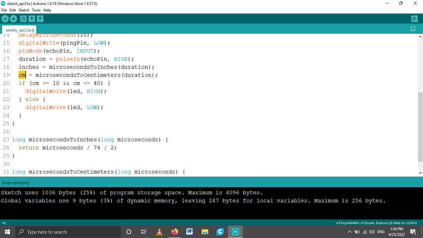
Due to time constraint I used ultrasonic arduino code n tested all on arduino first. As attiny44 does not support serial library of arduino so I changed its codes and added if statement that if any object is detected then turn the led on if not keep the led off
Note: I choose ultrasonic sensor because this economical sensor provides 2cm to 400cm of non-contact measurement functionality with a ranging accuracy that can reach up to 3mm. Each HC-SR04 module includes an ultrasonic transmitter, a receiver and a control circuit. Also this sensor has additional control circuitry that can prevent inconsistent "bouncy" data depending on the application. for more information click here
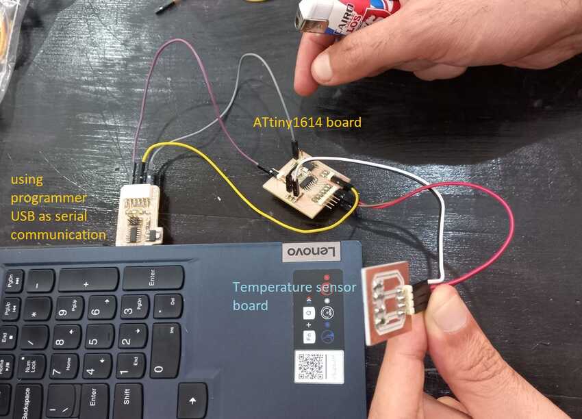
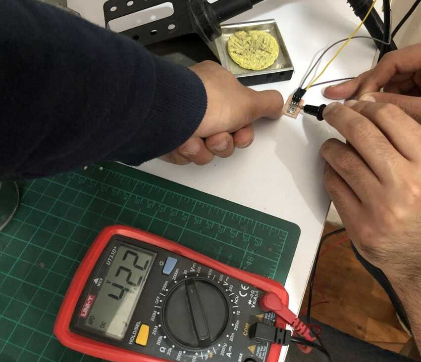
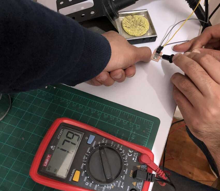
Connections: 4 pins of ultrasonic sensor were connected to Vcc, Gnd, Trigger pin: A4 and Echo pin: A5 respectfully. as for the LED on pin 7.
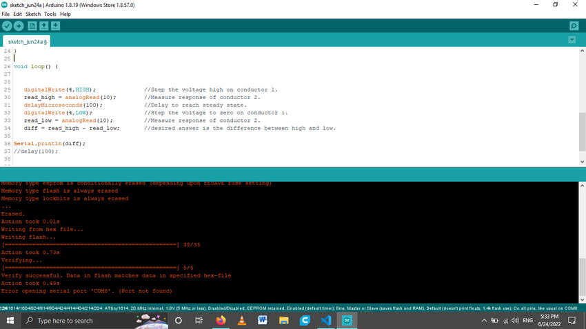
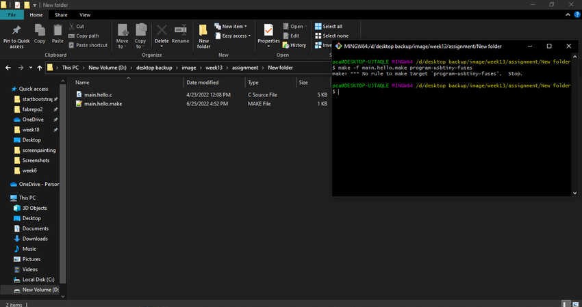
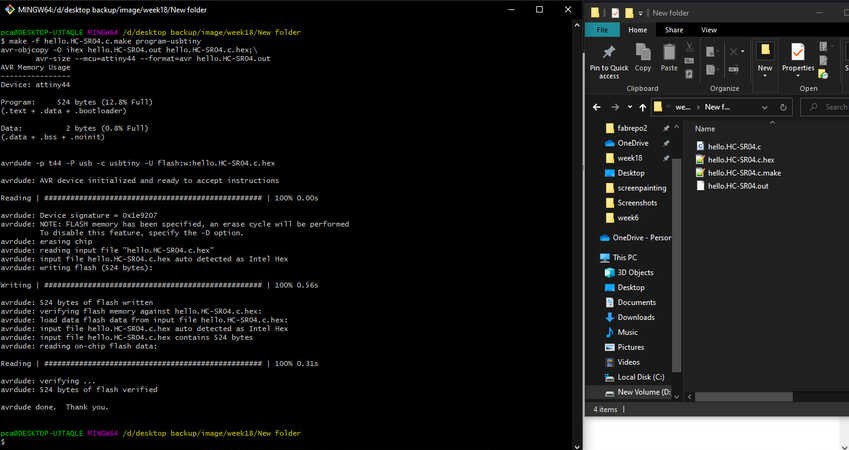
I used the arduino IDE toolchain to upload my sketch. I first tried the Hello.HC-SC04.c and make file and use the comamnd line tool chain, it worked but the reading wasn't proper so I will get back to it after finishing the assignment another way.
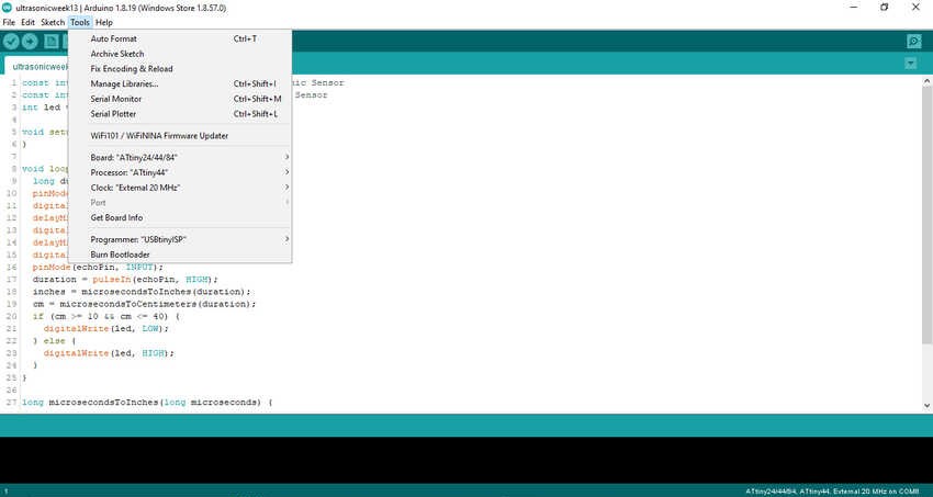
I choose from the boards attiny44 and 20MHGZ crystal and the programmer USBtinyISP from the tools menu(as shown in the picture below), then I selected upload using programmer from the sketch menu.

Arduino file
image

Learning outcome:
I learned alot this week, specially how the MCU functions and collects input analog and digital reading. Not to mention, then how to convert that reading according to our purpose in coding.
Here is the video

Voila its done

To sum up, I completed the following:

    • √ Linked to the group assignment page.
    • √ Documented what you learned from interfacing an input device(s) to microcontroller and how the physical property relates to the measured results.
    • √ Document your design and fabrication process or link to previous examples.
    • √ Explained the programming process/es you used.
    • √ Explained problems and how you fixed them.
    • √ Included original design files and source code.
    • √ Included a ‘hero shot/video’ of your board.

image

#Challenges 1

I tried to upload hello.HC-SC04.c and make file and use the ultrasonic but had error.

#Solution 1

I am trying to find out the solution but due to time constraints I have kept it for the end.
After presentation: I had rechecked all my connections from my board to the programmer. also had tried to upload an old code which was done successfully, just to make sure that the board and connections are working well. That debugging was a successful I found out that I was skipping a step in make commands according to this documentation . But as I redid all according to the documentation it worked at last.
Instead of make -f main.hello.make I jumped to make -f main.hello.make program-usbtiny-fuses, so it didn't make the hex file and the out file which were primary for fuses.

image

Aknowledgment

    • √ Thanks to my instructors for providing valuable resources.