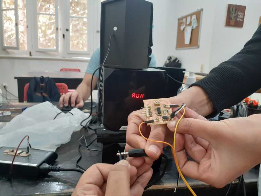
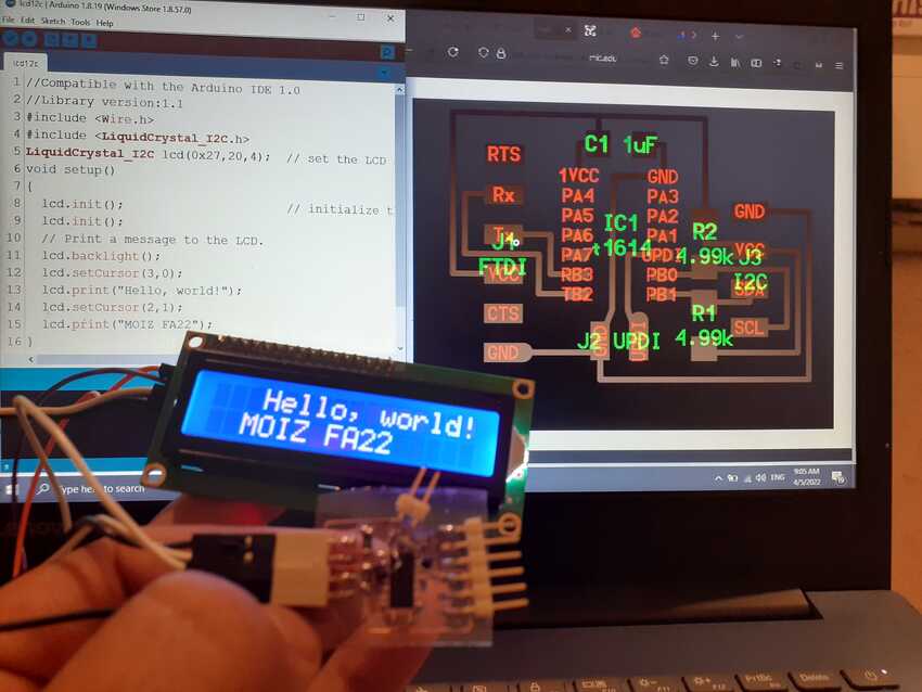
Week 10 Output devices

Assignments:

Group assignment:

    • Measure the power consumption of an output device.
    • Document your work (in a group or individually)

Individual assignment:

    • Add an output device to a microcontroller board you've designed and program it to do something.

Learning outcomes:

    • Demonstrate workflows used in controlling an output device(s) with MCU board you have designed.

Weekly Practices

I found this week a little bit easy as I had some knowledge about electronics in the maker maker diploma . Thanks to our Instructor who guided us in week 8 to have a pcb with pin headers on all GPIOs . I used that fabricated attiny1614 from week 8 to practice different types of output devices on it.

image

Example of LED :
I used Prof Neil’s arduino C code hello LED code .

image

Big thanks to our instructors who provided us with mosfet board which acted as a switch and control the output devices through it

image
image

Here is the video LED with mosfet.

Example of display:
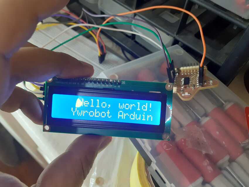
I then practiced on a small LCD 16 x 2 with a 12c module , at first I couldn't find a complete code with a liquid crystal library. Special thanks to amany ayman who gave me the code needed.
This is the new code
//Compatible with the Arduino IDE 1.0 //Library version:1.1 #include #include LiquidCrystal_I2C lcd(0x27,20,4); // set the LCD address to 0x27 for a 16 chars and 2 line display void setup() { lcd.init(); // initialize the lcd lcd.init(); // Print a message to the LCD. lcd.backlight(); lcd.setCursor(3,0); lcd.print("Hello, world!"); lcd.setCursor(2,1); lcd.print("Ywrobot Arduino!"); lcd.setCursor(0,2); lcd.print("Arduino LCM IIC 2004"); lcd.setCursor(2,3); lcd.print("Power By Ec-yuan!"); } void loop() { }

image

Example of DC motor: I also practiced on a small geared dc motor as it is one of the output devices. And I used a normal fade example to operate on a DC motor.

File: fade arduino code.

Example of speaker:
It was turn to explore the speaker - I used both a small buzzer and the Lab’s big speakers . For the buzzer I used the fade example code with it.
As for the other speaker, Prof Neil’s C code so that is why i had to use the previous board attiny44 which was fabricated on week 6 and use the command terminal tool chain to make fuse it.

Small Video demonstrating all output devices working together on a 1 signal pin for the mosfet

File: fade arduino code.

image

Weekly Assignments

Group assignment

Here is the link to the group assignment page.
This week’s group assignment was to measure the power consumption of an output device, so we explored yellow geared dc motor and measured its power consumption on both devices:
Power supply: current - 0.09 Amp
Multimeter: current - 8.56 M.Amp
The vast difference is observed in both devices, especially in current which is very vital for every device and electronics. The multimeter is more advanced and more accurate / precise reading compared to the power supply unit.

image image
image

Our instructors had prepared for us different hello boards for various output devices so we could explore all of them in the group assignment. As none of us had done the speaker one before the group assignment day, our instructor prepared the connections and showed us hello.speaker.45. It was a really amazing adventure and very fascinating to see and understand the relationship between the power and sound. Also many of us, including me, were impressed to hear a very smooth and good tune compared to the buzzer. And we all started thinking about the amount of creativity and hard work had put into this line of work / while writing the code..

image

Individual assignment

As for the individual assignment I had to add an output device to a microcontroller board that I had designed and program it to do something, I chose to take this opportunity to explore fabricating a flexible pcb circuit for hello i2c board. Also I made the mosfet board as a practice and trial.
To do that I tried a new vinyl machine called vinyl silhouette cameo 3 and used the copper roll as my material. Special thanks to assistant instructor Noha, who guided me with her documentation for using the vinyl machine. And for the copper sheet settings she guided me to the fab academy link which both were very useful. To my surprise I had a perfect cut from the first trial. I was very happy because of the results and also because this was my very first flexible circuit. Also when I did an internship in fab lab Egypt I went to some tutorials like this they were also very helpful for the first timers to get acquainted with the machine and its process.

image
image

For this machine it has its own CAM software which is silhouette studio (as mentioned earlier I had already installed it) so I opened the application and inserted the trace image of hello i2c board from this link.
I specifically chose this board as I wanted to explore the display output more as I will be using it in my final project. Also found the only board which didn’t have a transistor as here in the inventory the transistor’s footprint is a little bit different so instead of designing a new from the scratch I chose a ready one to concentrate on fabrication of a new thing.
I traced the image by navigating to the object toolbar menu.
Then I had to recheck the sizes as it looked very huge compared to what I imagined.
Then from the top right I clicked on the send tab to enter the cutting settings, which is well discussed in the academy’s archive …
Force = 6
Speed = 1
I found out that the material settings weren't applicable for this material as copper was not found in the list so that is why from any material I customized it according to the instructions given in the archive.

image
image

It was recommended to use a hard backing for the copper sheet so luckily I found a plastic sheet which I used as my backing. I had stuck a small area of copper sheet on the plastic sheet and then inserted it in the machine.
For the first cut command, I tested by a square and circle which turned out to be perfect.
Then I started cutting my board which is shown in the video.

image

The most important process is to peel off the excess sheet area and keep the traces intack in one piece so that was a trial and error for me as due to lack of this knowledge, I had already damaged 2 traces :)
But thankfully it turned out ok.

image
image image

Finally I soldered the components, which was already a new thing for me to solder on a plastic sheet. I burned out some tracks and the plastic sheet also :)
Then I burned the bootloader by reviewing week 4 and 6 and 8
Finally I uploaded the trial arduino code to check for everything was alright, by the time I prepare Prof. Neil’s hello i2c code damage on the flexible circuit was too much that i didn’t continue and was satisfied with my progress.

File: lcd arduino code.

image image
image

Here are some hero shots.

image

Voila its done

To sum up, I completed the following:

    • √ Linked to the group assignment page.
    • √ Documented how you determined power consumption of an output device with your group
    • √ Documented what you learned from interfacing output device(s) to microcontroller and controlling the device(s).
    • √ Describe your design and fabrication process or linked to previous examples..
    • √ Explained the programming process/es you used.
    • √ Outlined problems and how you fixed them.
    • √ Included original design files and code.
    • √ Included a ‘hero shot/video’ of your board.

File: silhouette studio file.

#Challenges 1

Soldering flexible circuits.

#Solution 1

I used a flexible plastic sheet as my backing for the flexible circuit, so it can be easily cut in a vinyl machine. But while soldering it melted due to the high temperature of the solder iron which ended in burning holes on the pads, traces and the plastic backing itself. Due to this issue, there were many pads burned which made it very difficult to solder on it.
While peeling the excess copper sheet, my tracks which were very thin and weak also broke off with it. I had to compromise by adding legs of resistors to make a good connection. The UPDI pin of the MCU was not soldered and touching to the pad / tracks was detected while I was trying to burn the bootloader but instead got this long scripted message which I interpreted as this problem. I added a small part of the leg of the resistor on it as the pad had burned away. And made the connection like a bridge to avoid any further burns.

image

Aknowledgment

    • √ Special Thanks to Fablab specialist Noha Hani and Amany ayman, without them I could not have explored and learn new thing this week.