


Here is my Hero-shot of the week!
 Let's start first with the group assignment
We wanted to see how does the change of an analog reading affect the voltage signal in an input device. So our instructor Kamel made a demo for the temperature sensor using Neil's code. After programming the ATtiny1614 board we then kept the programmer to use its USB as a serial communication and connected the TX,RX pins with ATtiny1614 board which is also connected to the final board that makes the tempreture sensor. Here its reading through the interface
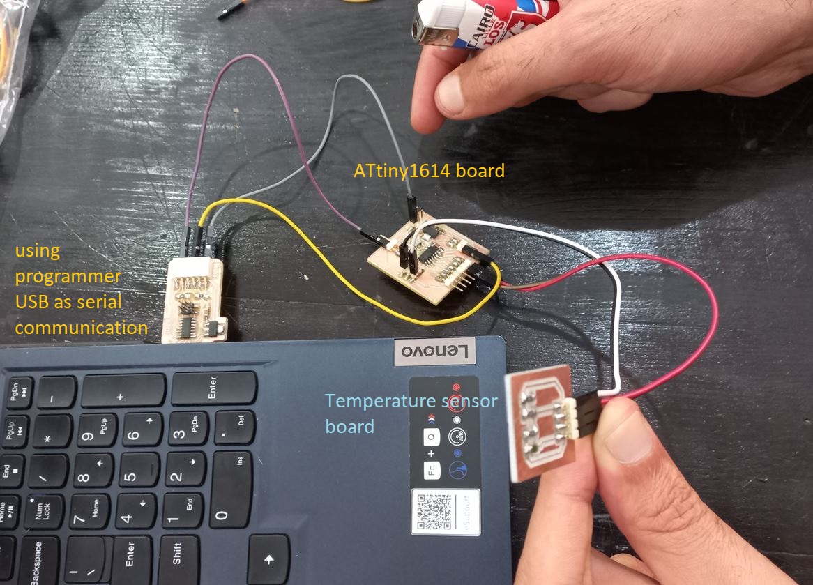
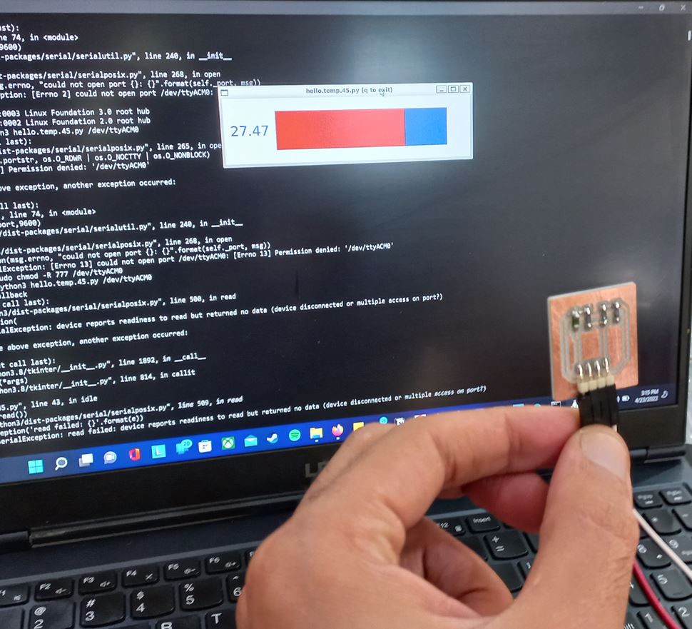
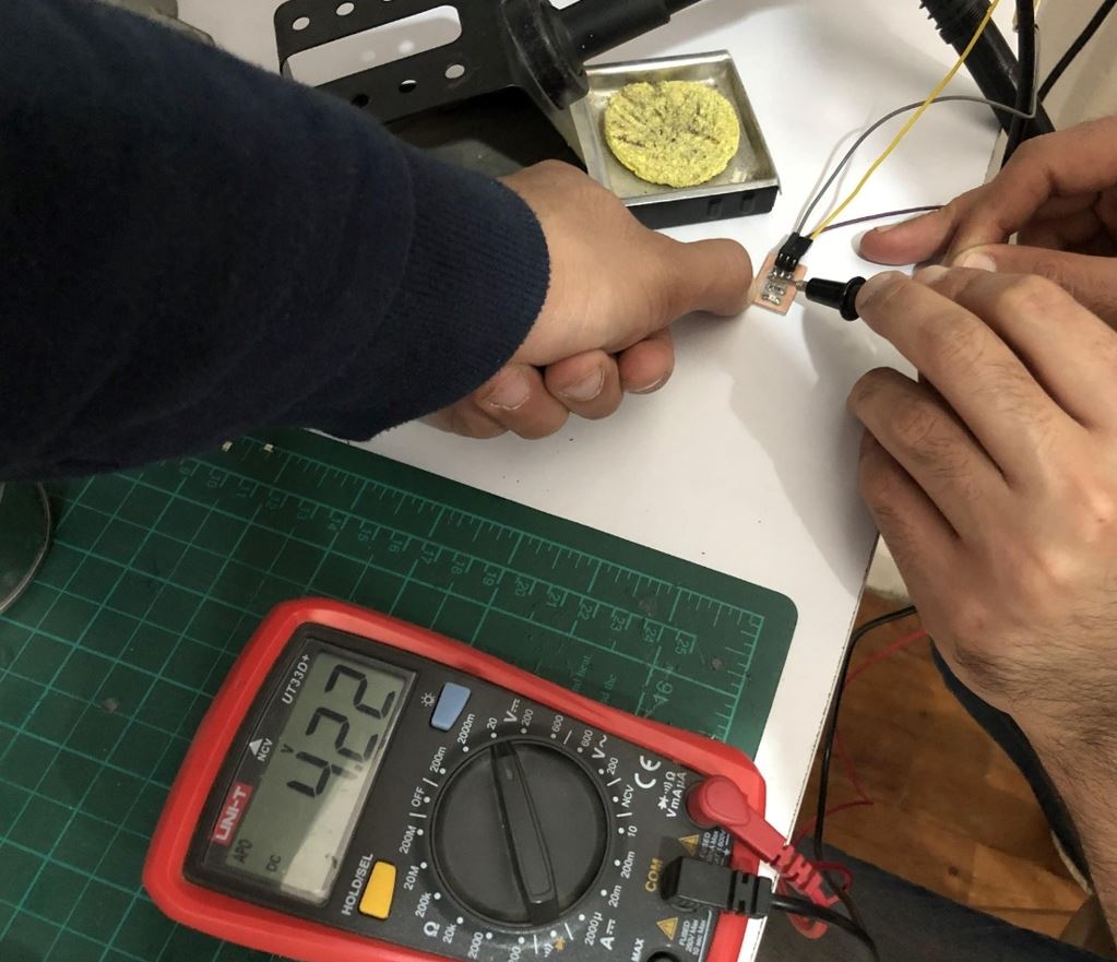
Then we tried to heat it up then let it cool and the GUI window would differ, We also measured the output signal from the sensor so when the temperature went up the voltage went down and vice versa..
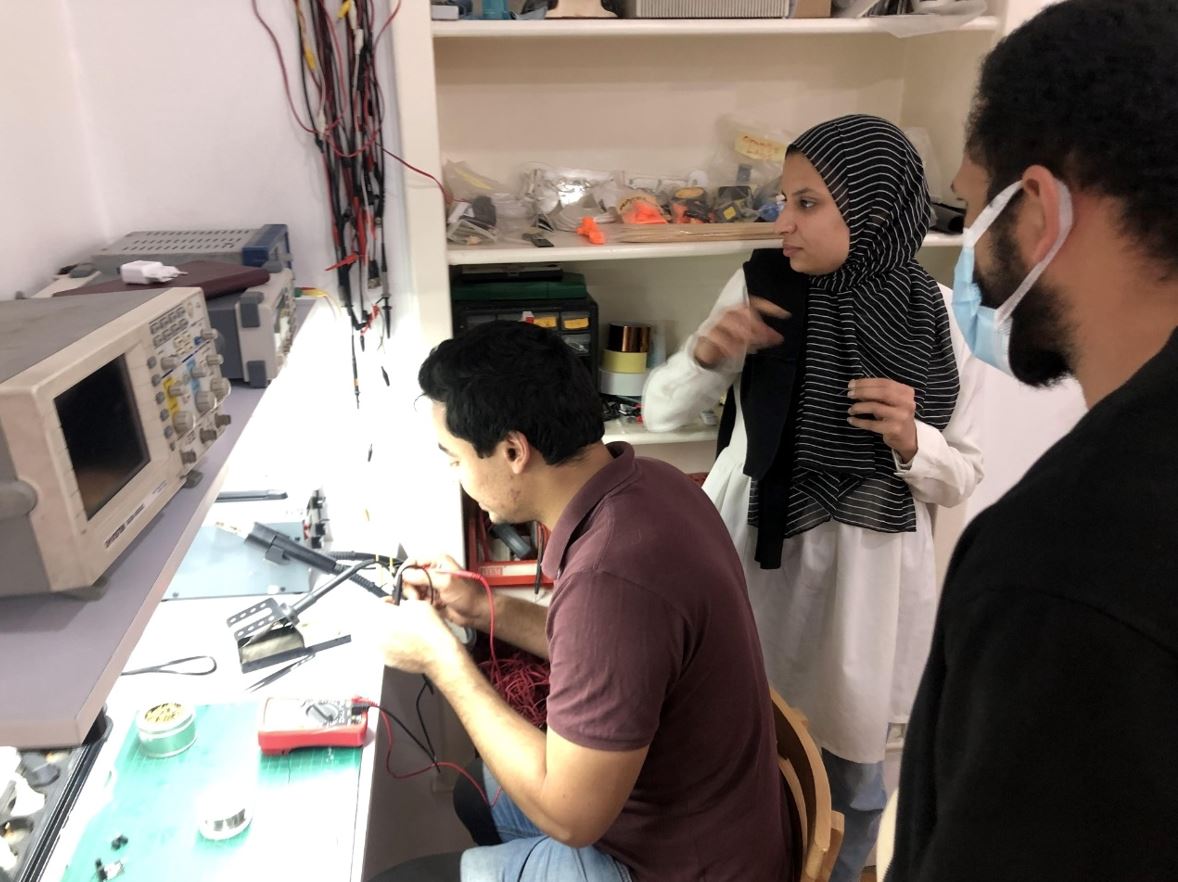
We also tried to read the varying signals coming out of the input device using oscilloscope. We used An LDR or light dependent resistor which is also known as photo resistor, photocell, photoconductor. It is a one type of resistor whose resistance varies depending on the amount of light falling on its surface. So, when light falls on the LDR then the resistance decreases, and increases in the dark. In the analog mode, we just kept reading the signal coming out of the LDR which varies upon the light as the next video shows.
And, in the digital mode we programmed the ATtiny that if there is light the LED in the ATtiny's board will be Turned OFF and if there isn't a light the LED will be turned ON, which depended on just reading from the LDR High or low values which are near 5V and 0V only.
Now, The assignment!It was an interesting week to know more about all those sensors that detects what's around us let it be motion, sound, light, images, force and more.. So I tried measuring two things which are temperature and motion. I used the same ATtiny1614 board I made in the Programming week controlling both sensors. In all my attempts I used the same board from my programming assignment which has ATtiny1614 as its MCU, you can find it here
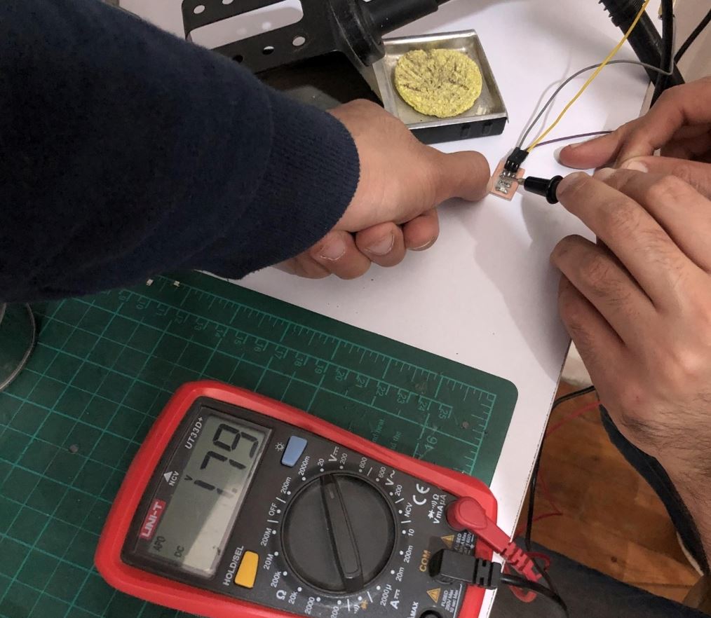
Temperature SensorI used LM35 sensor, it only had 3 pins which were VCC, GND, and signal. So searched for its pinout and found this:
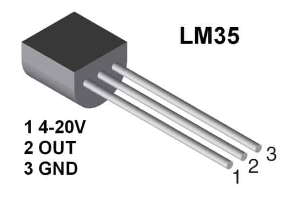
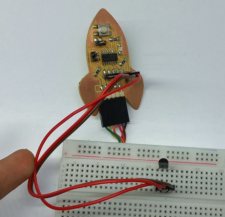
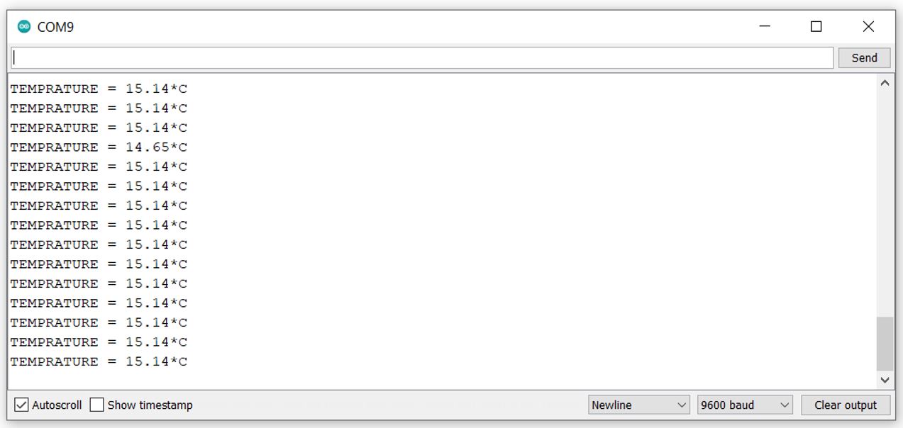
I connected the signal pin to an analog pin "ADC" to be able to convert the analog in to a digital input the MCU can understand, So connected it to PA3. I didn't have pins connected to VCC and GND of my board so I used another 2 pins and wrote to them HIGH and LOW as a power source. After programming the board with UPDI programmer, I just connected the sensor with ATtiny1614 board and connected the FTDI cable with the board so it could have serial communication with my laptop through TX and RX pins. So here is the circuit and the reading I got from LM35.
So here is the final code
          int val;
          int tempPin = 10;
          int vccpin = 8;
          int gndpin = 9;

          void setup()
          {
            Serial.begin(9600);
            pinMode(tempPin, OUTPUT);
            pinMode(vccpin, OUTPUT); //powering up VCC and GND pins
            pinMode(gndpin, OUTPUT);
            digitalWrite(vccpin, HIGH);
            digitalWrite(gndpin, LOW);
          }
          void loop()
          {
            val = analogRead(tempPin); //reads the signal from the input pin
            float mv = ( val / 1024.0) * 5000; //converts the reading into milli-volts
            float cel = mv / 10; //converts the mv into celsius degrees
            Serial.print("TEMPRATURE = "); //the message which appears on Serial Monitor
            Serial.print(cel);
            Serial.print("*C");
            Serial.println();
            delay(1000);
          }
PIR Sensor
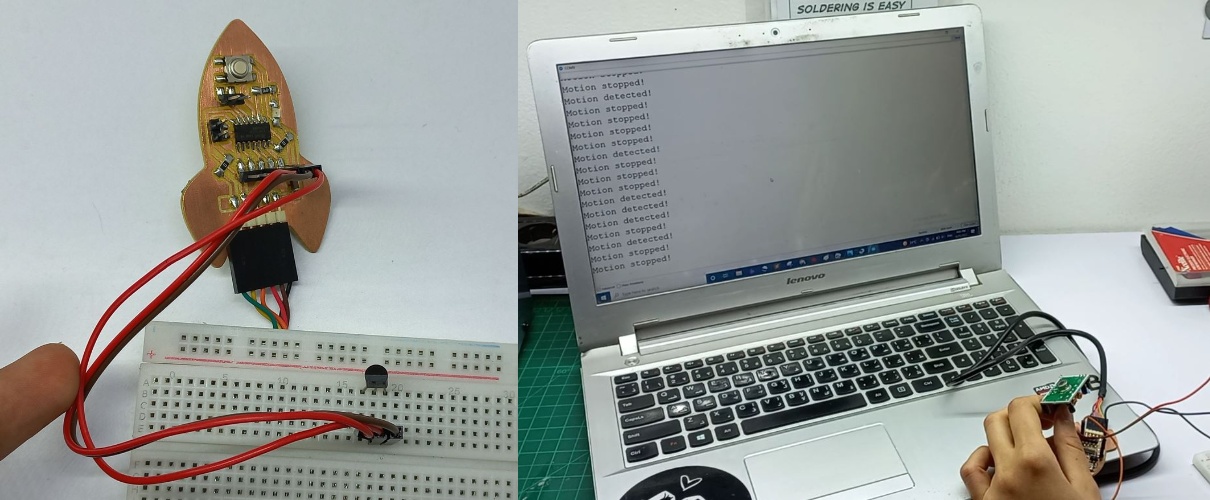
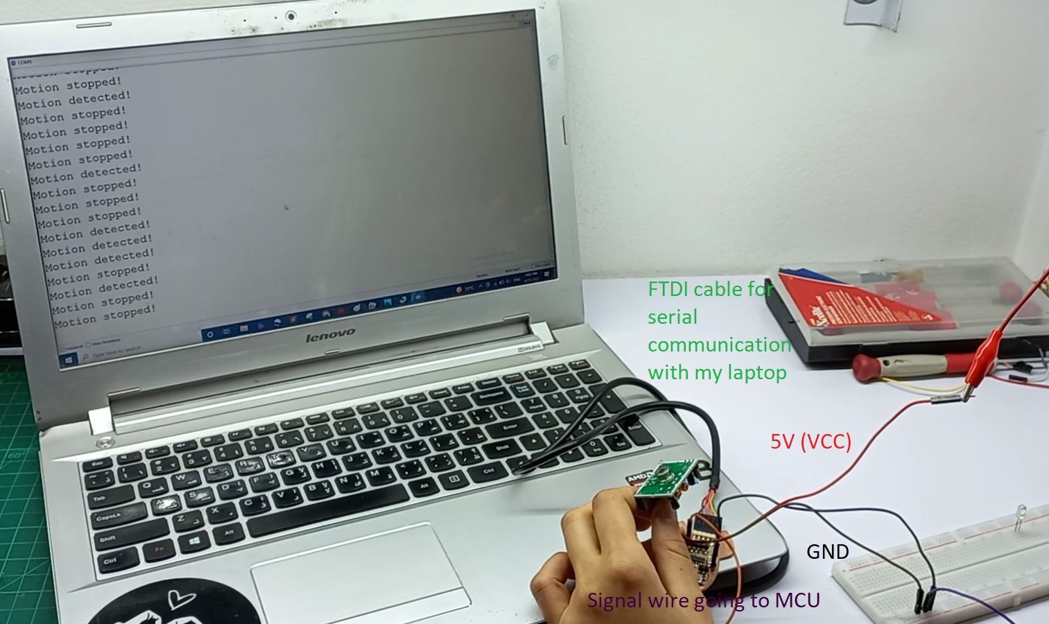
PIR stands for "Passive Infrared sensors". That's because their principle of operation is based on the detection of infrared energy emitted by a moving body. Its connection was the same as the temperature sensor just GND,VCC and signal, But to work properly I needed to connect it with the power supply and connect common ground between the board and the power supply. And connected my board with the lapptop to see the readings through FTDI cable. just like the following image.
Then changed the code a bit so it could send "detected" when it senses motion and "stopped" when there was no motion. As following code:
          int sensor = 10;              // the pin that the sensor is atteched to
          int val = 0;                 // variable to store the sensor status (value)

          void setup() {
            pinMode(sensor, INPUT);    // initialize sensor as an input
            Serial.begin(9600);        // initialize serial
          }

          void loop() {
            val = digitalRead(sensor);   // read sensor value
            if (val == HIGH) {           // check if the sensor is HIGH
              Serial.println("Motion detected!");
            }
            else { //when motion is not detected
              Serial.println("Motion stopped!");
            }

            delay(1000);
          }
And it worked!