3. Computer Aided design
Assignment
model (raster, vector, 2D, 3D, render, animate, simulate, …) a possible final project
compress your images and videos
post a description with your design files on your class page
Files compression
Windows viewer for images
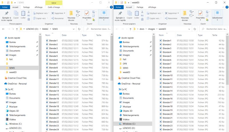
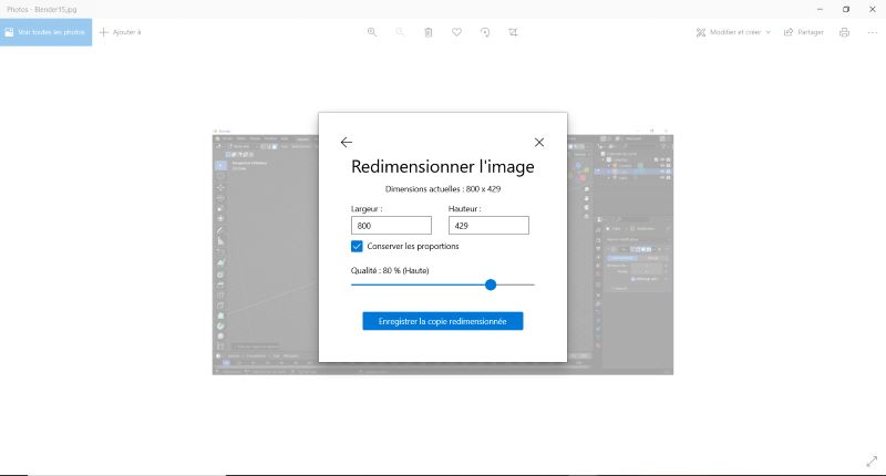
I use windows viewer for images. I use resize function. And select 800 large.
 |
|---|
| Compression results. |
I can choose quality too.
 |
|---|
| I use the compression menu and select 50% quality. |
 |
 |
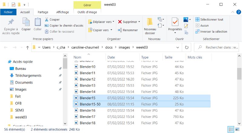
| Here is the compression result : 225Ko to 25 Ko. |
It’s quite long to deal with all the images.
GIMP for images
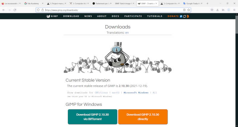
I download GIMP and a plug-in BIMP to deal with a lot of images at the same time.
 |
|---|
| I download GIMP. |
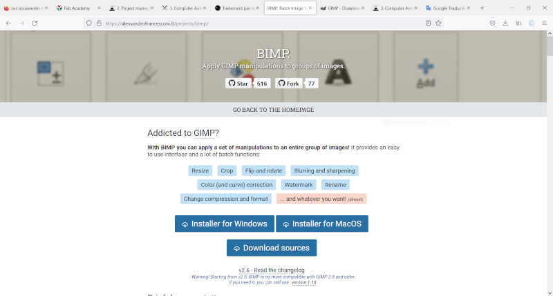 |
| I download Bimp plug-in. |
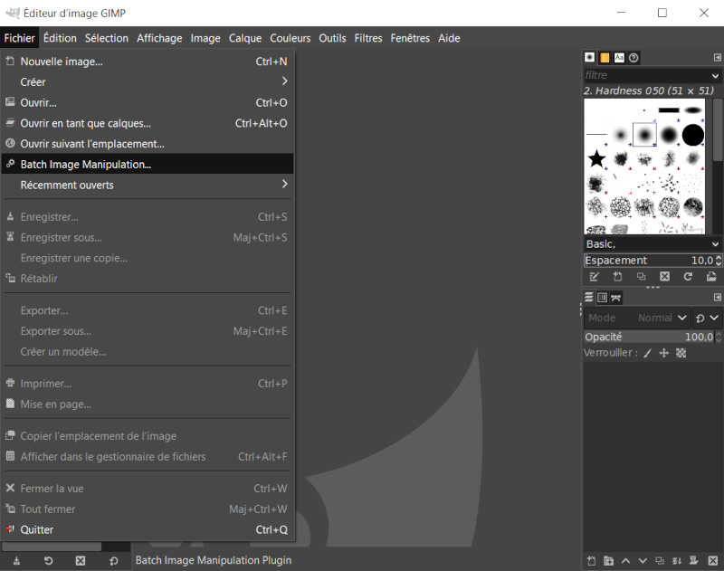 |
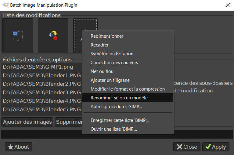
| Batch Image Manipulation function. |
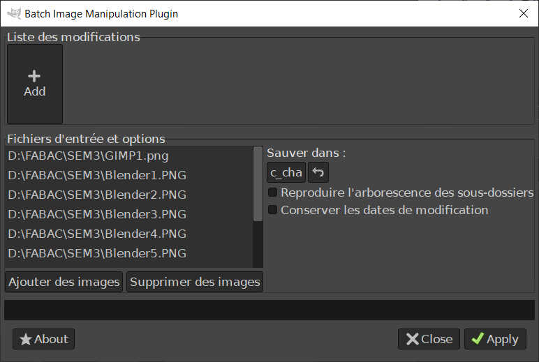 |
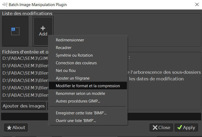
| I add all images I want to compress, convert and resize. I can choose a whole folder. |
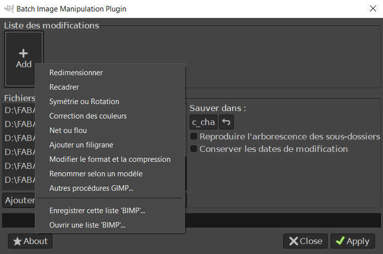 |
| I list all modifications I want to process. |
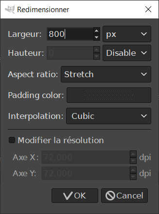 |
| Resizing. |
 |
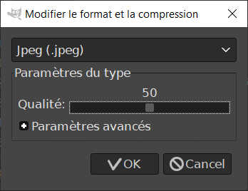 |
| Conversion and compression. |
 |
| Renaming. |
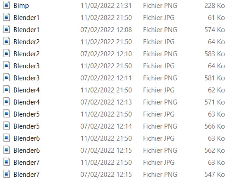 |
| Here is the result ! |
FFMPEG for videos
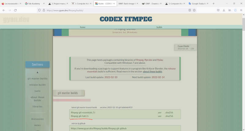
I started with this tutorial. I download ffmpeg for windows here.
 |
|---|
| I download ffmpeg full to be sure I have all what I need. |
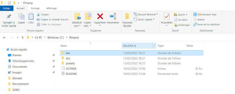 |
| Here are the files and I use git Bash to install them. |
I use this code to have information about the video I want to use :
ffmpeg -i input.mp4 -hide_banner
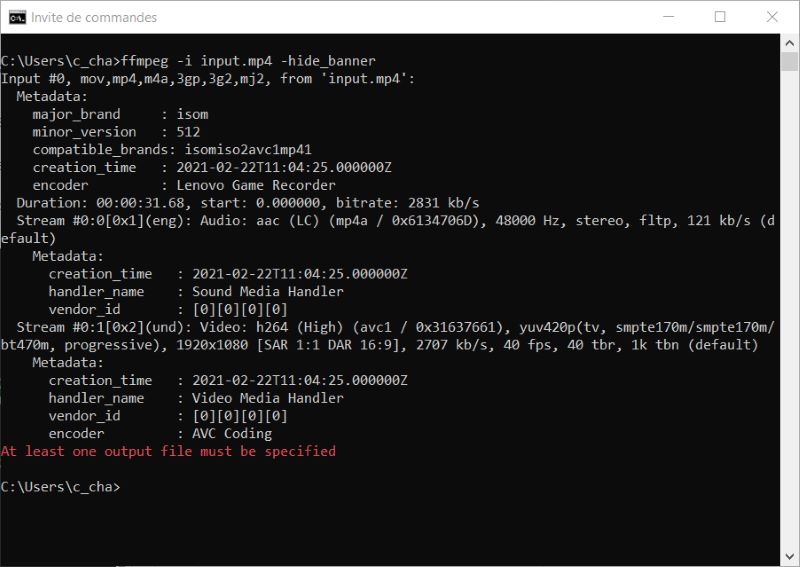 |
|---|
| Informations about the input.mp4 video. |
To know what kind of formats are used by ffmpeg :
ffmpeg -formats
There are more than 400 types !
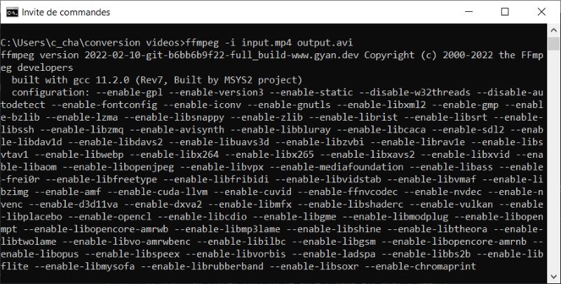
Mp4 converted to avi
ffmpeg -i input.mp4 output.avi
 |
|---|
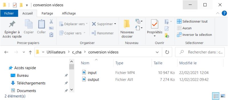 |
| output.avi created. |
When I open the video the quality is lower than the one of input.mp4.
To have the same quality I use this instruction -qscale 0:
ffmpeg -i input.mp4 -qscale 0 output2.avi
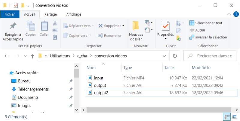 |
|---|
| output2.avi created. |
The size is bigger than the size of input.mp4 but quality is the same.
To change resolution
ffmpeg -i input.mp4 -filter:v scale=640:480 -c:a copy output3.mp4
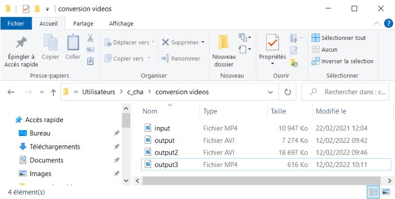 |
|---|
| output3.mp4 created. |
To compress the video
ffmpeg -i input.mp4 -vf scale=1280:-1 -c:v libx264 -preset veryslow -crf 24 output4.mp4
or
ffmpeg -i input.mp4 -vf scale=1280:-1 -c:v libx264 -preset veryslow -crf 23 output5.mp4
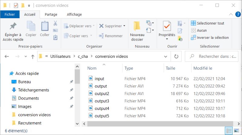 |
|---|
| output4.mp4 and output5.mp4 created. The first one with -crf 24 and the second one with -crf 23. |
To delete audio in a video
You can use -an:
ffmpeg -i input.mp4 -an output6.mp4
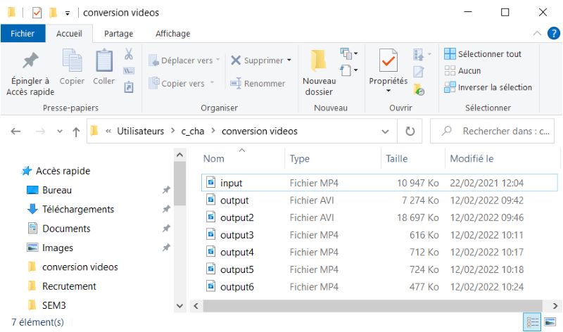 |
|---|
| output6.mp4 created without sound. |
To see changes you have done
You can use ffplay output6.mp4 to play output6 and watch the result. I use thaut to see the real size and quality of my video.
More instructions here
You can find more instructions here like : - convert video to audio - add subtitles - add an image to an audio file - …
GIF creation
To create a GIF I try two strategies.
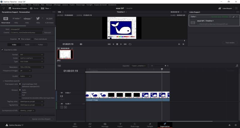
GIF creation with DaVinci Resolve
The first one with DaVinci Resolve. I’am used to create video with this software. When you register images with the same name incremented with number it create a media with them. I put them on the track and modify the speed. After that I create the video (.avi) and I compress it with ffmpeg and convert it to .gif with instruction :
InkscapeGIFoutput2.avi InkscapeGIFoutput2.gif
 |
|---|
| Media done with images on DaVinci Resolve. |
 |
| GIF done with DaVinci Resolve and converted with ffmpeg. |
GIF creation with GIMP
You can create GIF directly with GIMP. I use the tutorial here to do that.
- First you open the first image of the Gif.
- Than you open all the images one by one using the menu “open as layer “.
- Than you click on
Filters>Animations>Replay animationmenu. It open a window in which you can play the animation. - You choose you speed at the bottom of the window.
- You optimize with
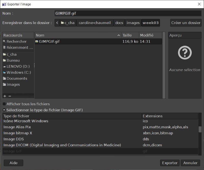
Filters>Animations>Optimize (for GIF)menu. - You register your Gif with
Files>Export Asmenu. - You choose the name and add .gif extension.
- You select .gif in the list and click to export.
- Don’t forget to select
As animationin the last window. - Click on Export to finalize your Gif.
 |
|---|
| You choose the name and add .gif extension. |
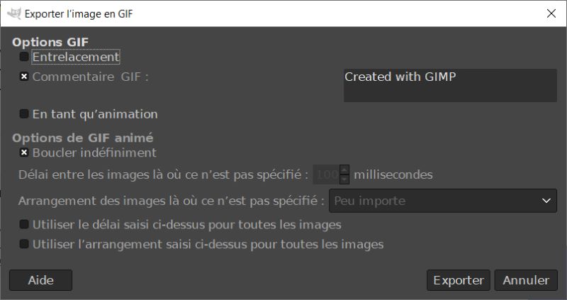 |
Don’t forget to select As animation in the last window. Here I have to click on “En tant qu’animation” button. |
 |
| GIF done with GIMP. |
2D Softwares
Illustrator CS2
I’am used to design with Illustrator which use vectors. I use the CS2 version which is free.
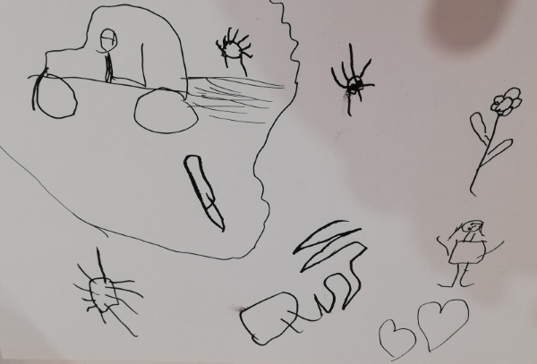
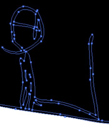
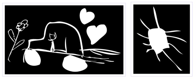
My children draw two scenes with black markers. I scan them and vectorize with Illustrator. I obtain curves. I modify them and use pathfinder to obtain this result :
 |
 |
|---|---|
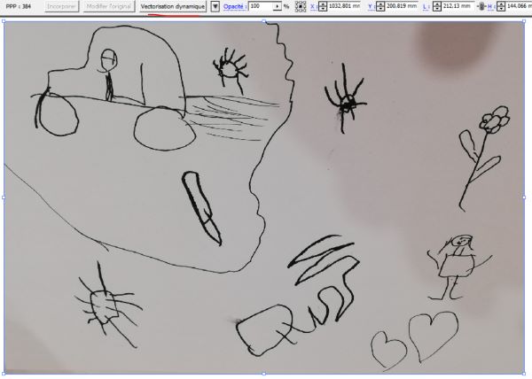
| Children’s drawings with black posca on white paper. | Image opened in Illustrator CS2. Click on vectorisation dynamique |
 |
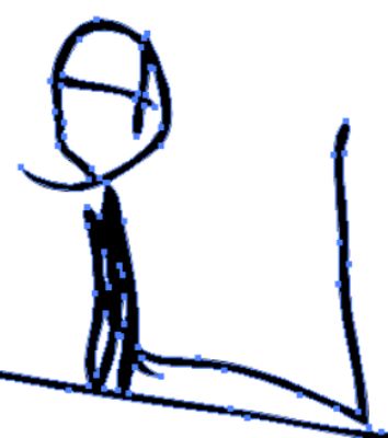 |
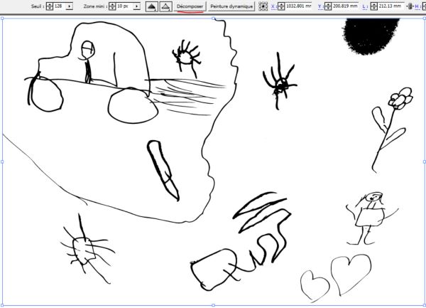
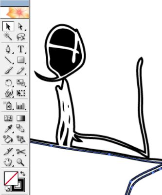
Image vectorized. Click on Décomposer |
Vectors. Pencil lines are surfaces. |
 |
 |
Click right dissocier and right Annuler le tracé transparent |
Vectors after switching colors between surfaces and lines. |
 |
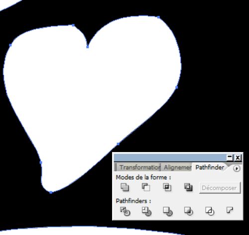 |
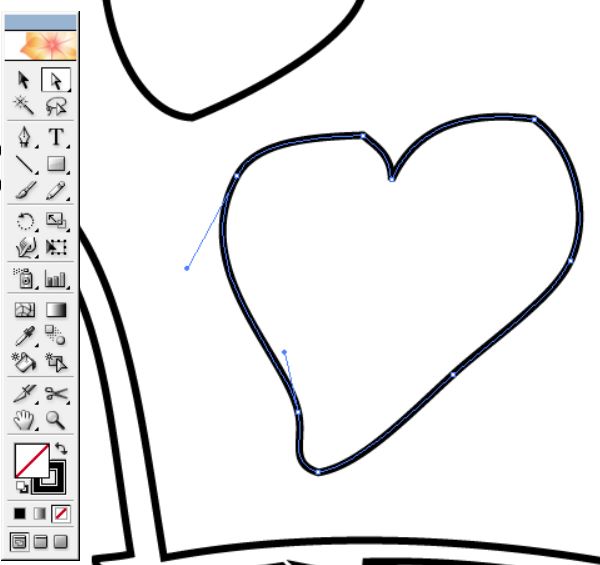
| After some modification here is an heart vectorized. | Using the pathfinder to create a surface to be engraved. |
 |
|---|
| Drawings of my children on illustrator prepared to be engraved and cut with laser cutter. |
I can use it to decorate the keyboard.
Inkscape
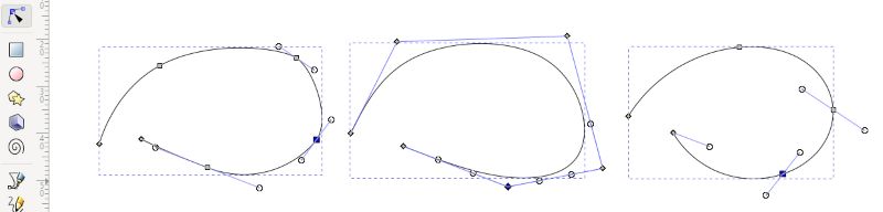
I download Inkscape to use a free software. I use different types of lines, change color and use pathfinder.
 |
|---|
| 3 lines done with 3 different tools. |
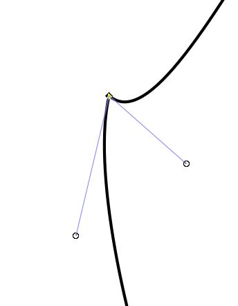 |
Corner nodes type with  . . |
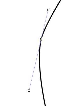 |
Corner nodes type with  . . |
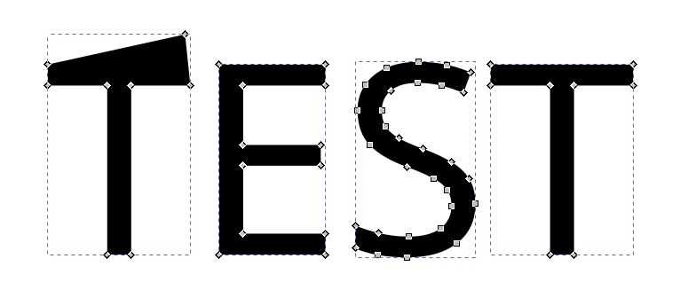
To vectorize text : First select text with selection tool  and click on
 Path > Object to path. Now your text is changed as image.
 |
|---|
| Vectorized text. |
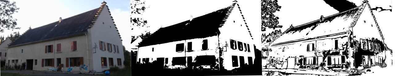
To vectorize an image : First select image with selection tool and click on Path > Trace Bitmap. Now you can choose parameters to obtain wath you want.
 |
|---|
| For examples two kind ok vectorized image with brightness cutoff or color quantization. |
I use GIMP like explained before to create a Gif to retrace what I have done :
|
|---|
| GIF done with GIMP retracing steps used to create a whale with Inkscape. |
Photopea
I use photopea online. It’s quite like photoshop but free and on-line. I’m not used to utilize that kind of softwares which use raster images.
 |
 |
|---|---|
3D Softwares
Blender
Blender use polygonal meshes mainly used for animations. I start with Feadi’s tutorial on zoom. Here is his website.
Here can you find my favorite shortcuts :
- Scroll to zoom
- Click on scroll to rotate (you have to select the object before)
-
Shift+ click on scroll to displace -
1or3or7to turn the view in the x, y, z direction. 5to change the type of perspective and5to go black0to see the camera view- Click on
gorrorsto glide, rotate or resize. You can click onxoryorzto select the axis you want for rotation, translation or resizing. And you can add the value of displacement you want by clicking on numeric keypad. You can also select and scroll to expand influence of your displacement.
 Vue > Cadrer selectionto center the object you have selected.- Select vertices and click on
Fto create a surface between them. - To create a hole : Select surface,
E,S,E. Alt+ select an edge of a loop to select the loop.Kknife tool to divide a mesh.Ctrl + Alt + 0put the camera in the direction of the current view.
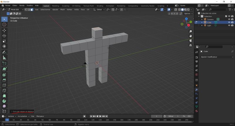
I make my first step on blender by creating a sort of “human-being”.
 |
|---|
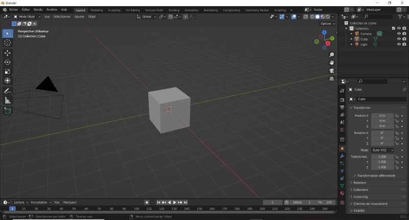
| When you open a new file you start with a cube. |
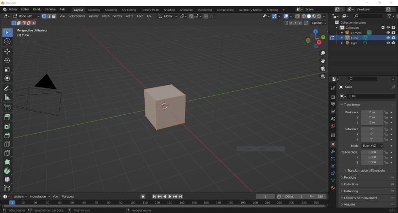 |
| Change Mode object into Mode Edit |
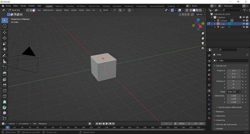 |
| Select surfaces and click on the top of the cube to select the surface. |
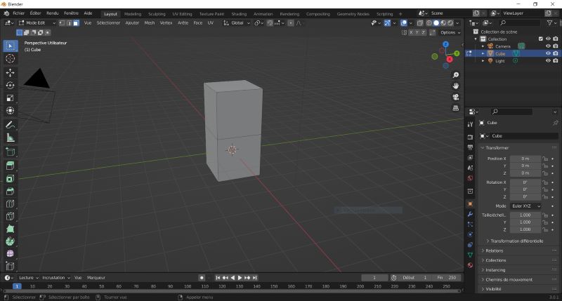 |
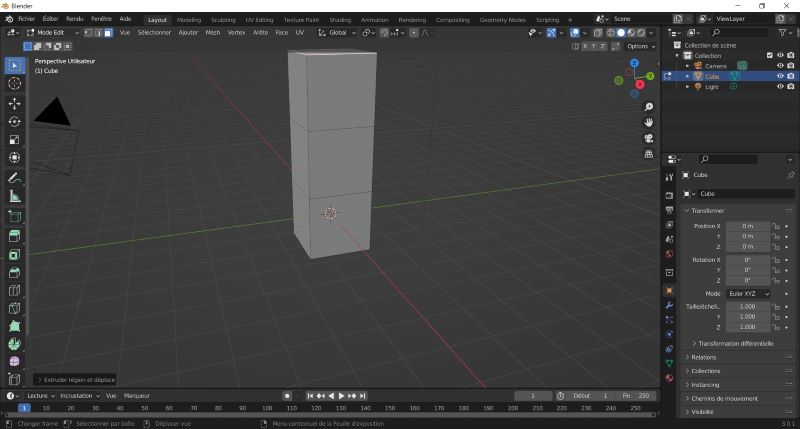
| Click on “e” (for extrusion) and 2 and click enter. A second cube 2 units long appears at the top of the first one. |
 |
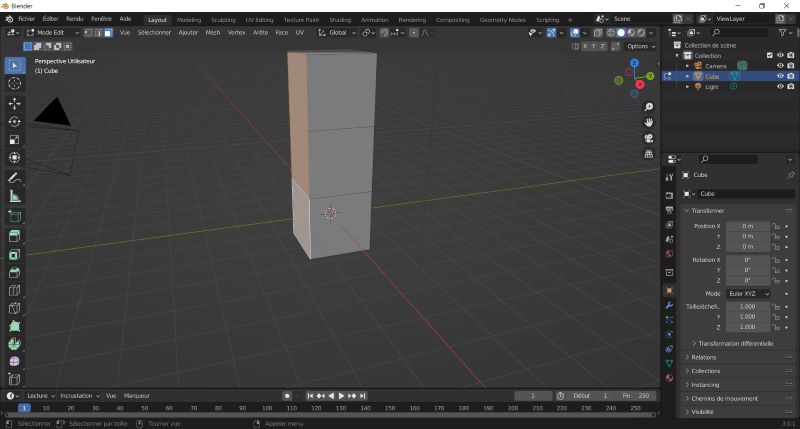
| Repeat the operation selecting the surface at the top. A third cube 2 units long appears at the top of the second one. |
 |
| Select all the surfaces on the left side and repeat the extrusion process. |
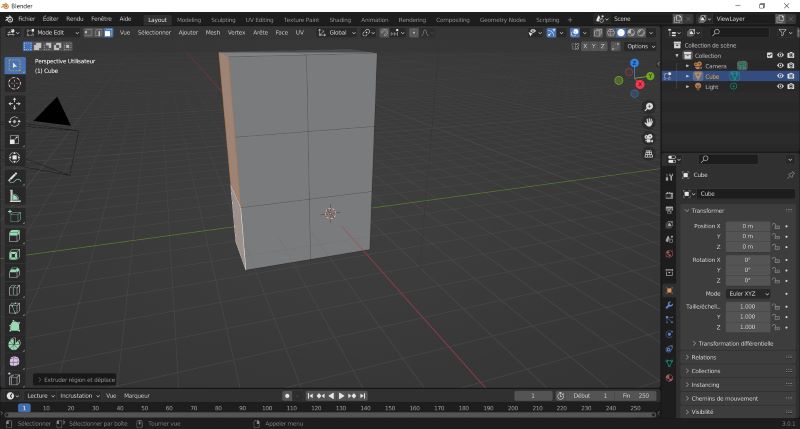 |
| Now you have a block like that. |
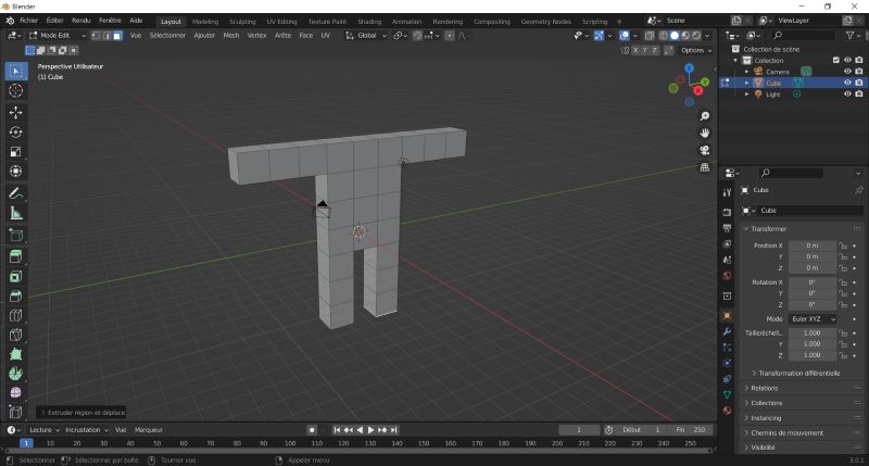 |
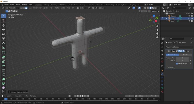
| Repeat extrusions selecting the surfaces to obtain something like that. |
 |
| Now you can add a head by the same process. You can change the value of the extrusion to obtain some smaller or bigger meshes. When you add something you have a menu in the left corner. |
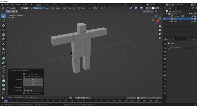 |
| You can change some parameters in this menu. |
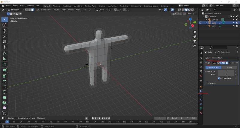 |
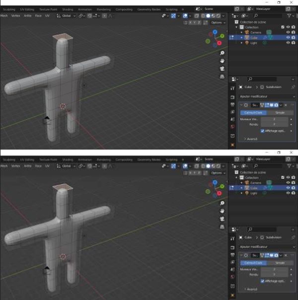
| You can select the wrench tab and select this function into the list. It creates surfaces between meshes. |
 |
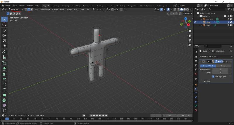
| You can change parameters to detail surfaces. You can see here an object with more surfaces. |
 |
| In the Mode Edit, you can select surfaces, points or straights to change the meshes like at the beginning. |
 |
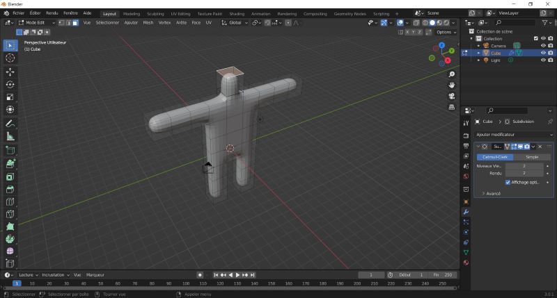
| Here you can see an extrusion of the head. |
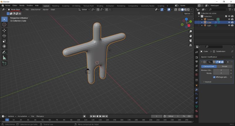 |
| You can go back to the Mode Object. You don’t see meshes any more. |
 |
| You can click right on the object and select smooth shading. You can have smooth surfaces. |
 |
| You can go back to the Mode Edit and select straight (or surfaces or points) to change meshes. |
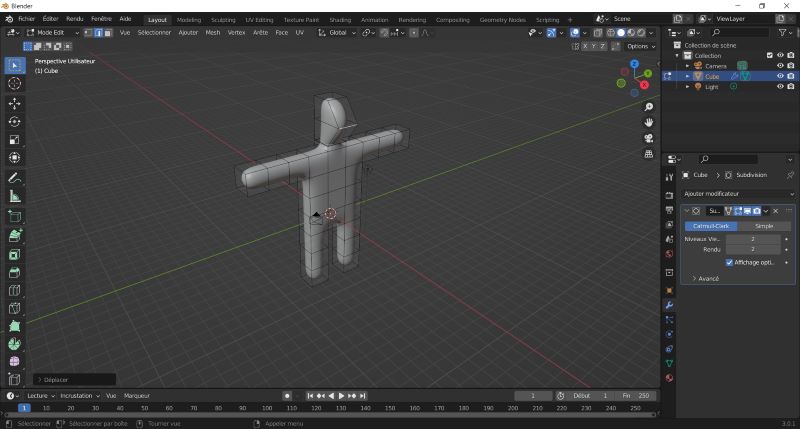 |
| Here I use the g shortcut to lengthen the head. |
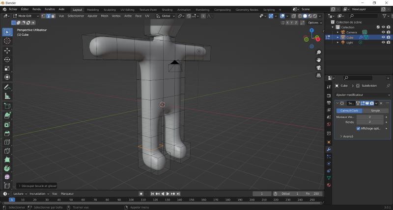 |
| You can click on ctrl+r to add a loop where you click on the meshes. |
After that I can change meshes to obtain something more realistic if I want.
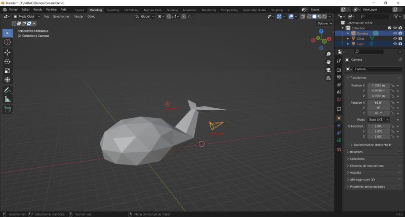
I start to represent a whale for my final project.
I use a sphere and 3 cones to do it. To merge this geometry together I delete surfaces between them and merge selecting nodes and using Mesh > Fusion > By distance. I can choose the distance under which points will be merged.
 |
|---|
| The whale created thanks to blender. You can see the camera (yellow) and the light (orange). |
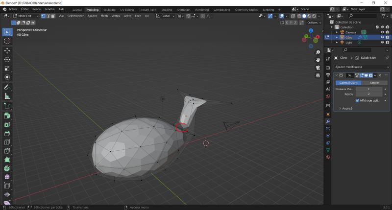 |
| When I create surfaces associated to meshes I obtain different part (using the wrench tab like explain before). |
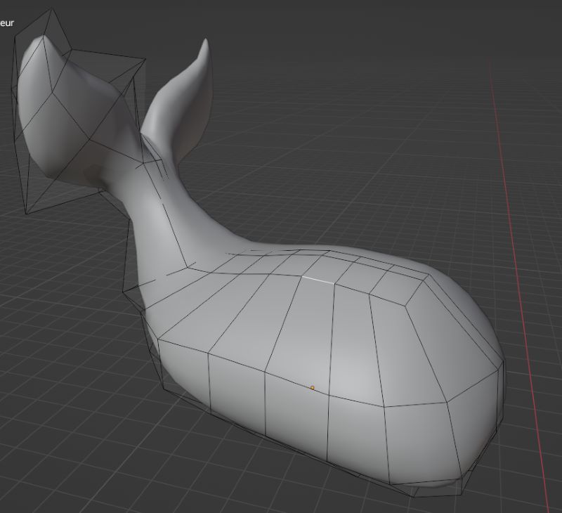
I had problem with the geometry of the tail and restart my design with cubes.
 |
|---|
| The whale created thanks to blender with cubes I model. I use mirror function to create both size of the whale. |
I use blender to create a rendering.
- First I choose material and color for the object. I can adjust texture too.
- Then I can add lights, place them and adjust type and power for them. It change the rendering. I can use 3 points of lights like explained here.
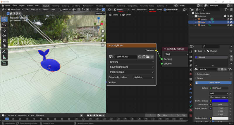
- Then I add a landscape founded here. I choose a swimming pool.
 |
|---|
| Whale design with Blender. |
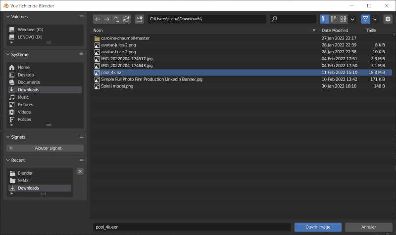 |
| File I choose for the “world”. |
 |
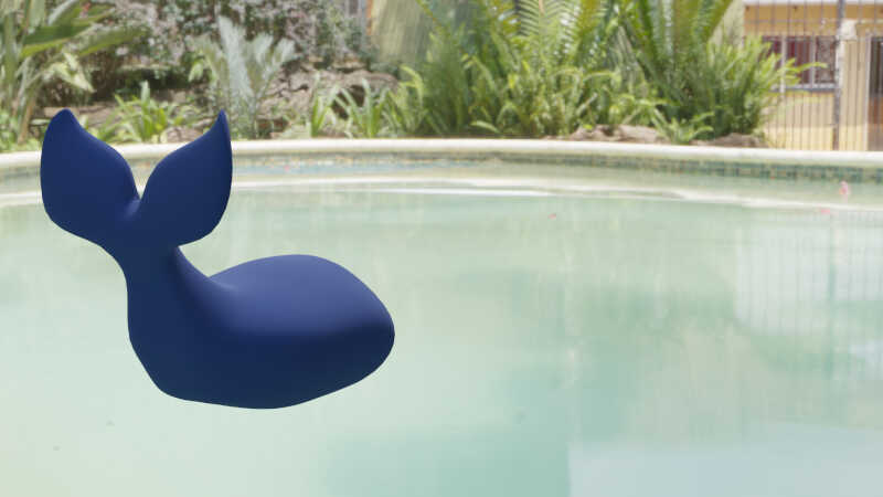 |
| Whale in the swimming pool. |
Now to create animation I use this tutorial.
Add > Armature creates like a “bone”.
In the Edit Mode you can select the bone created and move, rotate, extrude, scale, usw it.
After that you select first the object, secondary the armature and Ctrl+P "Armature deform". Now object and armature are associated.
Now you apply like an influence zone for each bone.
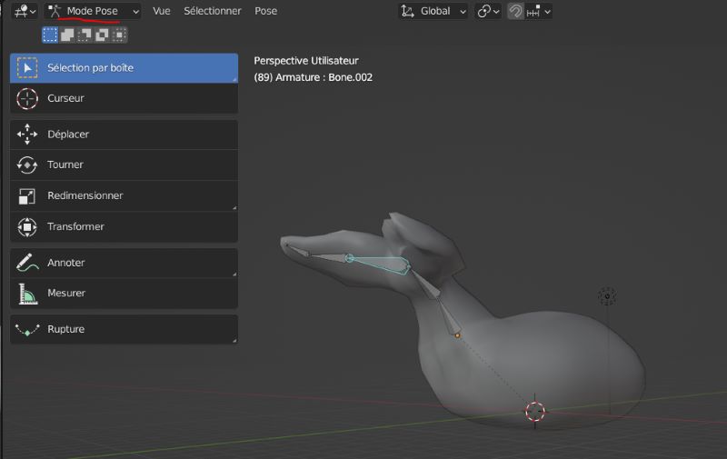
After that you can select one bone and go in Mode Pose to move all the bones.
 |
|---|
| Bones positions. |
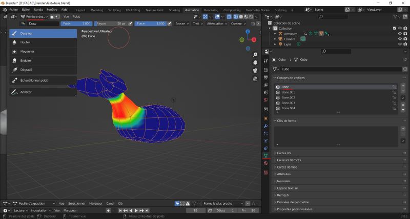 |
| Influence zone for each bones. |
Animation :
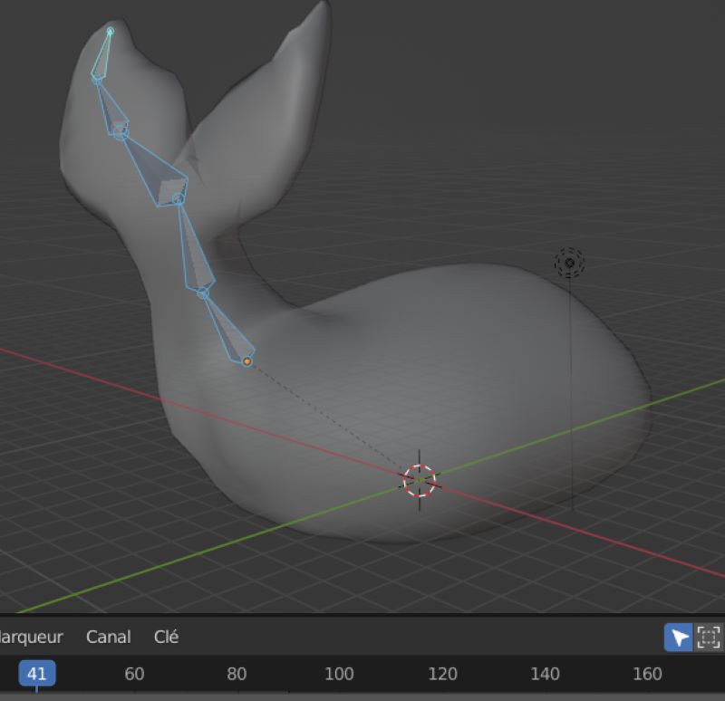
You select one moment in the time line. You select all the bones you want to save position then :
I > location, rotation and scale and it register the position
Register different positions at different moment and play the animation.
 |
|---|
| Position registered for time 41. |
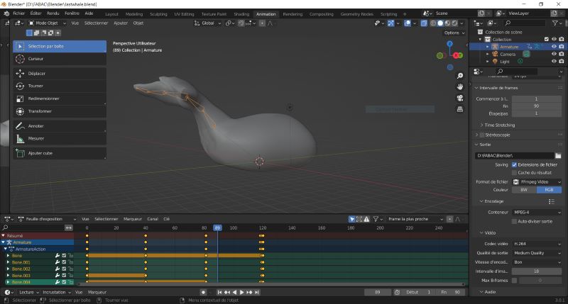 |
| Time line and export properties. |
 |
| Mp4 animation exported. |
FreeCAD
- FreeCAD use nubs design. I start without tutorial but plan to look at the Feadi’s one on his website.
I start with the part where watter should go out.
 |
|---|
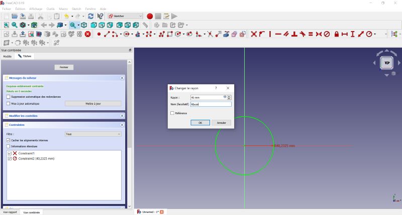
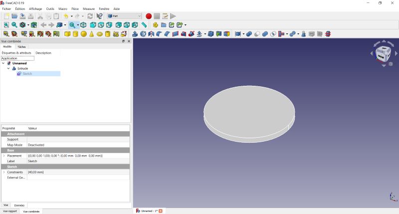
| Fist you can make a sketch in the sketcher menu. Here I make a circle with two constraints : centered on main axis with a 40 mm radius. |
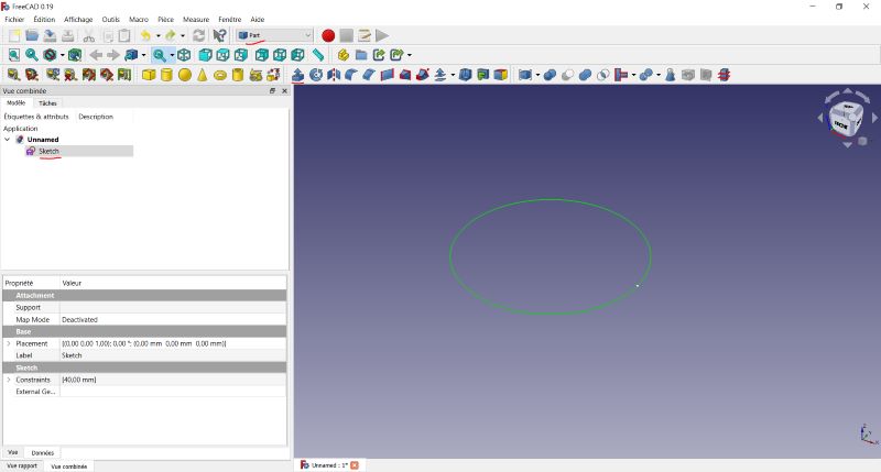 |
| Then I confirm and can see the circle in 3D space. This sketch appears in the tree on the left window. To do a part from this sketch you go in the part menu and select the sketch. |
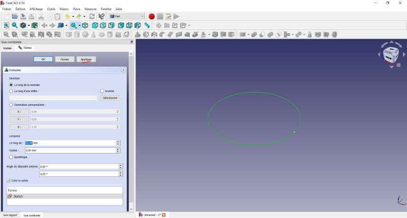 |
| Here you can choose direction, angle and length. |
 |
| You validate your parameters and can see the result. |
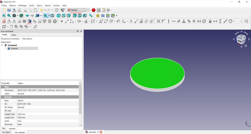 |
| To create a new extrusion at the top of the first one you select the surface and select sketcher menu. |
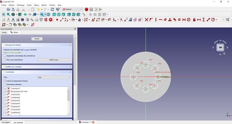 |
| Here I place 8 circles around a circle. Sketch stays white as long as the circles aren’t constrained. |
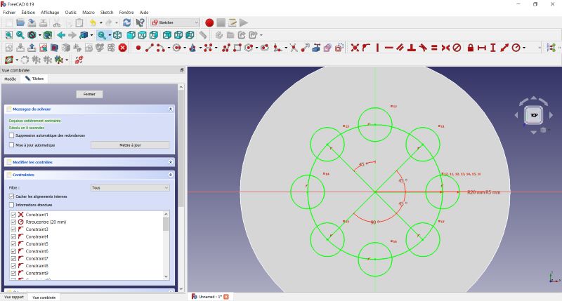 |
| Here they are all constraints. The sketch become green. |
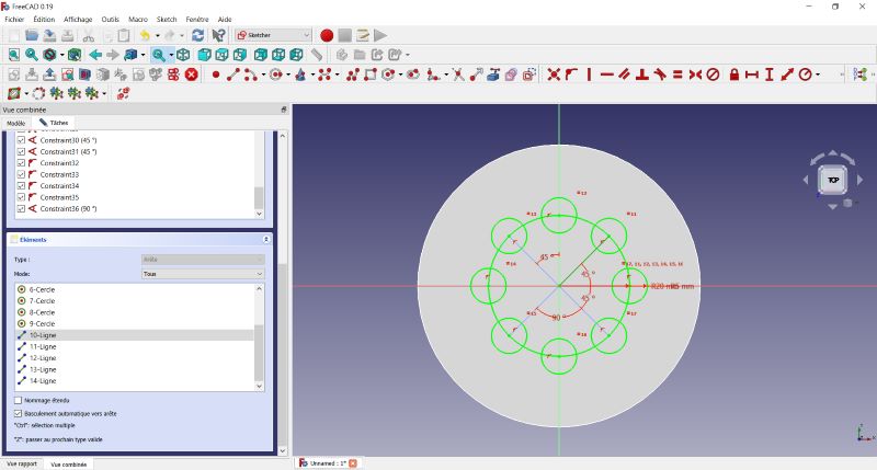 |
| I select all the line which are used to place circles and click right to define them as “Toggle construction line”. This lines becomes blue. |
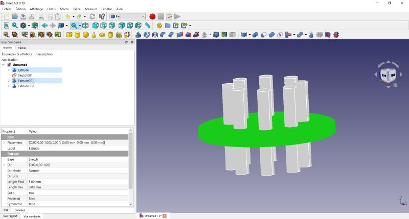 |
| I extrude all this circles. In the Part menu I select them and extrude them. Then I select two extrusions and make a boolean operation. |
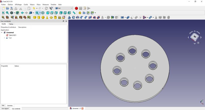 |
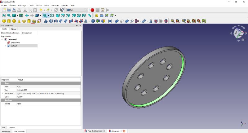
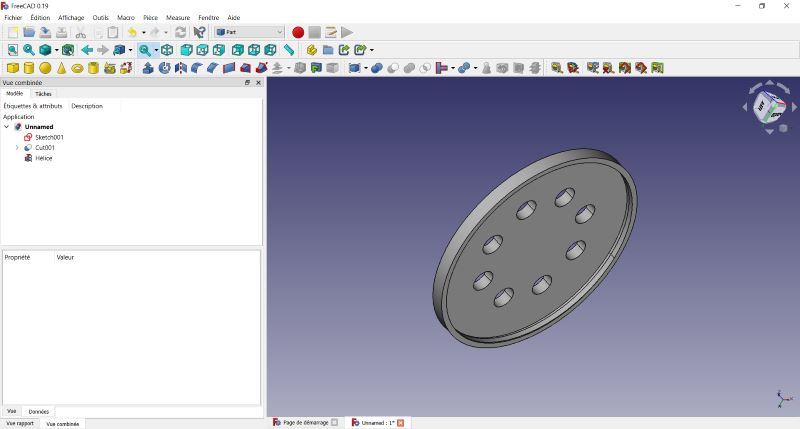
| I make a difference between them and obtain an opening part. |
Now I plan to add a thread to fix this part on the whale.
 |
|---|
| In Part Menu : After extrude a recess, I select surface on which I plan to do the tread and select “Création de primitives géométriques paramétrées” function. |
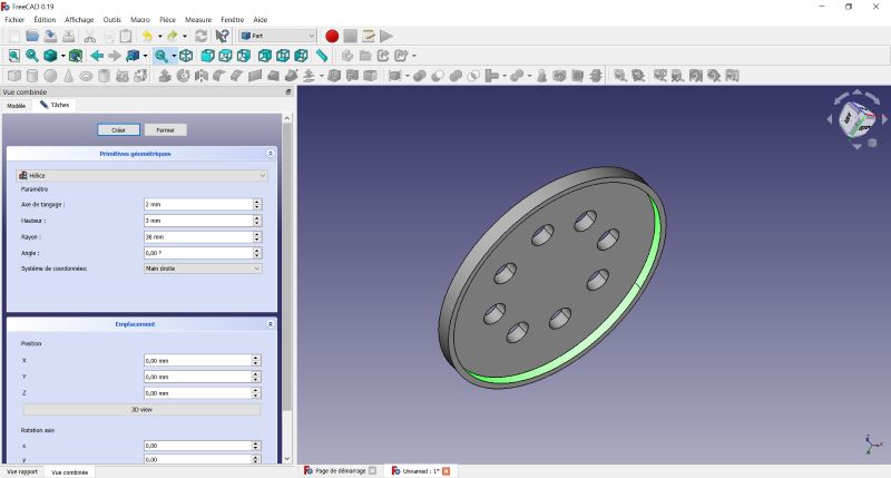 |
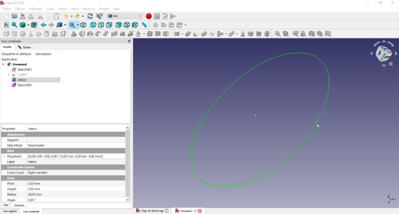
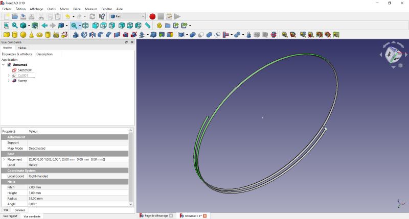
| Here I change parameters, selecting helix and defining the helix line. |
 |
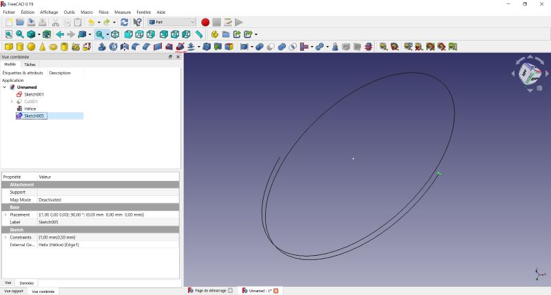
| Here you can see the helix line on the surface selected before. |
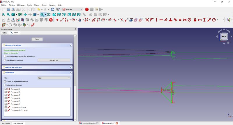 |
| I put a triangle sketch at the beginning of the line. Selecting the intersection between the line and the sketch plan. |
 |
| In Part Menu : I select this sketch and use the sweep tool to generate a part following the helix line. |
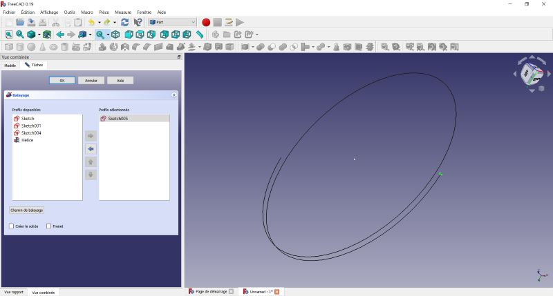 |
| First I choose the sketch and click on “chemin de balayage” button. |
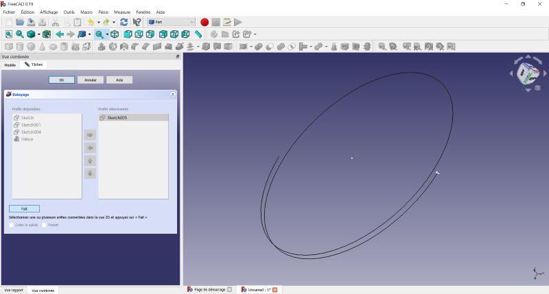 |
| I select the model tab. |
 |
| I select the helix line. |
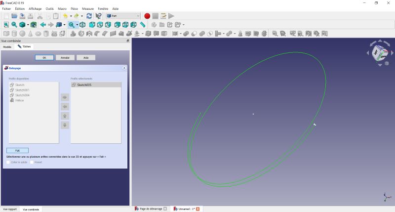 |
| I go back to the Taches tab. |
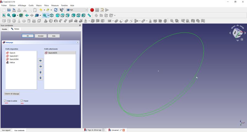 |
| I select “Creer le solid” and “Frenet”. Then OK. |
 |
| The sketch follows the line to create the part. |
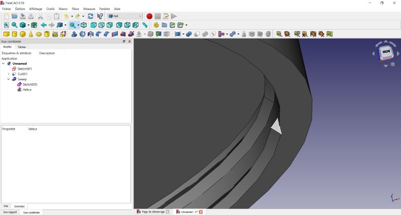 |
I try to merge both parts but it doesn’t work. I change the thickness of the first part and it works. Now I have to change the triangle profile for a standard profile for a screw.
3D model
Here is the 3D model of the whale (lowpoly) done with blender :