

Embedded Networking and Communications
*********
Group assignment:
Send a message between two projects
Individual assignment:
design, build, and connect wired or wireless node(s) with network or bus addresses
**********
(1) 😊 Welcome to the week of Embedded Networking and Communications, this assignment has one goal: to explore network systems to communicate two or more development boards, this is a topic that has many possibilities, since there is a wide variety of protocols that can be used.
You can check all the valid protocols for this assignment here:
http://academy.cba.mit.edu/classes/networking_communications/index.html
During Output Devices week I designed the JOSAMD 1.0 board on which I included pins for the SCL (serial clock) and SDA (serial data) outputs.
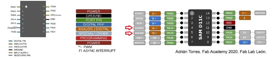
(2) Board with HEADERS for SDA and SCL

(3) The purpose of including these HEADERS is to make the board networkable with the I2C protocol, so its time has come as I haven't
used them in any assignments so far.
The first step was to do a deep research about this protocol, one of the essential resources for this assignment is the following document:
Source: https://www.nxp.com/docs/en/application-note/AN10216.pdf
Pros and cons of different protocols:

**********
(4) i2C protocol
I2C (Inter-Integrated Circuit) is a serial bus interface connection protocol. It is also called TWI (Two Wire Interface) as it uses only two wires for communication. These two wires are SDA (Serial Data) and SCL (Serial Clock).
I2C is an acknowledgment-based communication protocol, that is, the transmitter checks if the receiver sends an acknowledgment after transmitting the data to know if the data is received by the receiver correctly.
I2C works in two modes:
• Main mode (before master)
• Peripheral mode (previously slave)
The SDA (Serial Data) cable is used for data exchange between the main device and the peripheral device.
SCL (serial clock) is used for synchronous clock between both devices.
The main device initiates communication with a peripheral device. Requires the address of a peripheral device to start the conversation.
The I2C device has a unique 7 or 10 bit address. Therefore, to access these devices, a parent device must address them using the unique 7- or 10-bit address.
I2C is used in many applications like reading RTC (real time clock), accessing external EEPROM memory. It is also used in sensor modules such as gyroscopes, magnetometers, etc.
************
https://descubrearduino.com/i2c/
I2C Theory Of Operation:

(5) I2C hardware architecture

(6) In addition to this information, I reviewed a large number of resources in my native language, which were very useful for me to be successful in this assignment.
(7) After this investigation I felt more confident to start. I take this opportunity to give special thanks to my local instructor Iván for his mentoring in the development of this project.
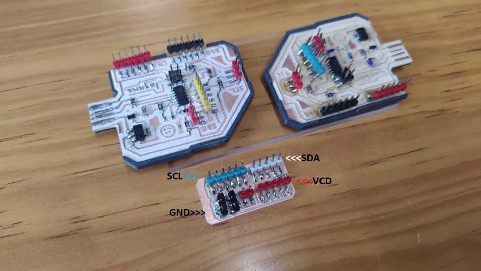
The first thing I did was make a schematic sketch of the board that I will use as a jumper to connect the SDA, SCL, GND, VCD cables and the Pull Up resistors.
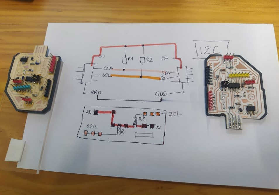
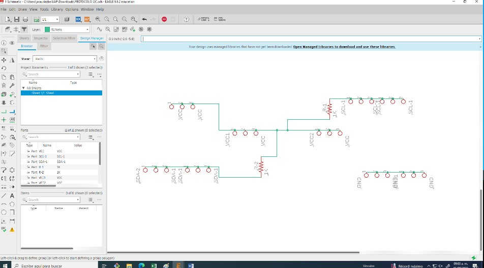
(8) This was the first prototype that I drew in Eagle, although after analyzing it for a while, I realized that it would be a bit awkward to solder and connect the cables in that position.
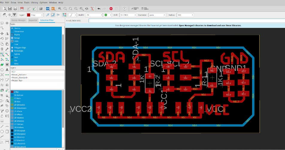
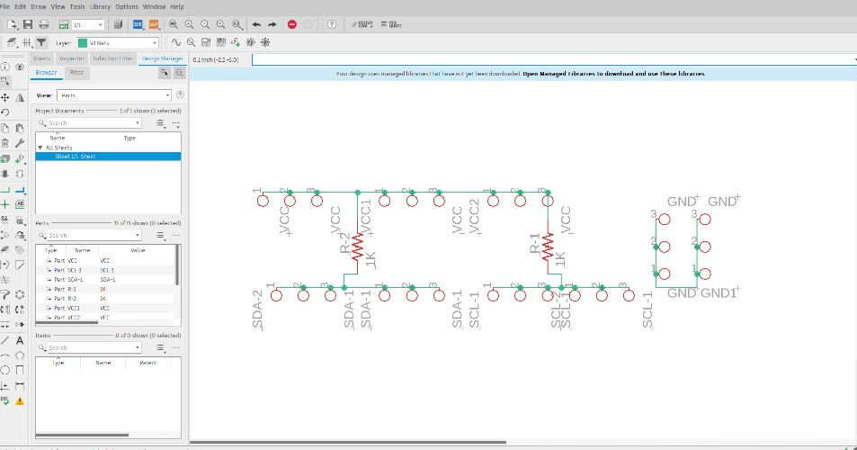
(9) So I decided to make a 2.0 version by placing the headers aligned to the edges of the board, in such a way that when soldering I would have more space, also connecting the cables would be more comfortable.
Second design:
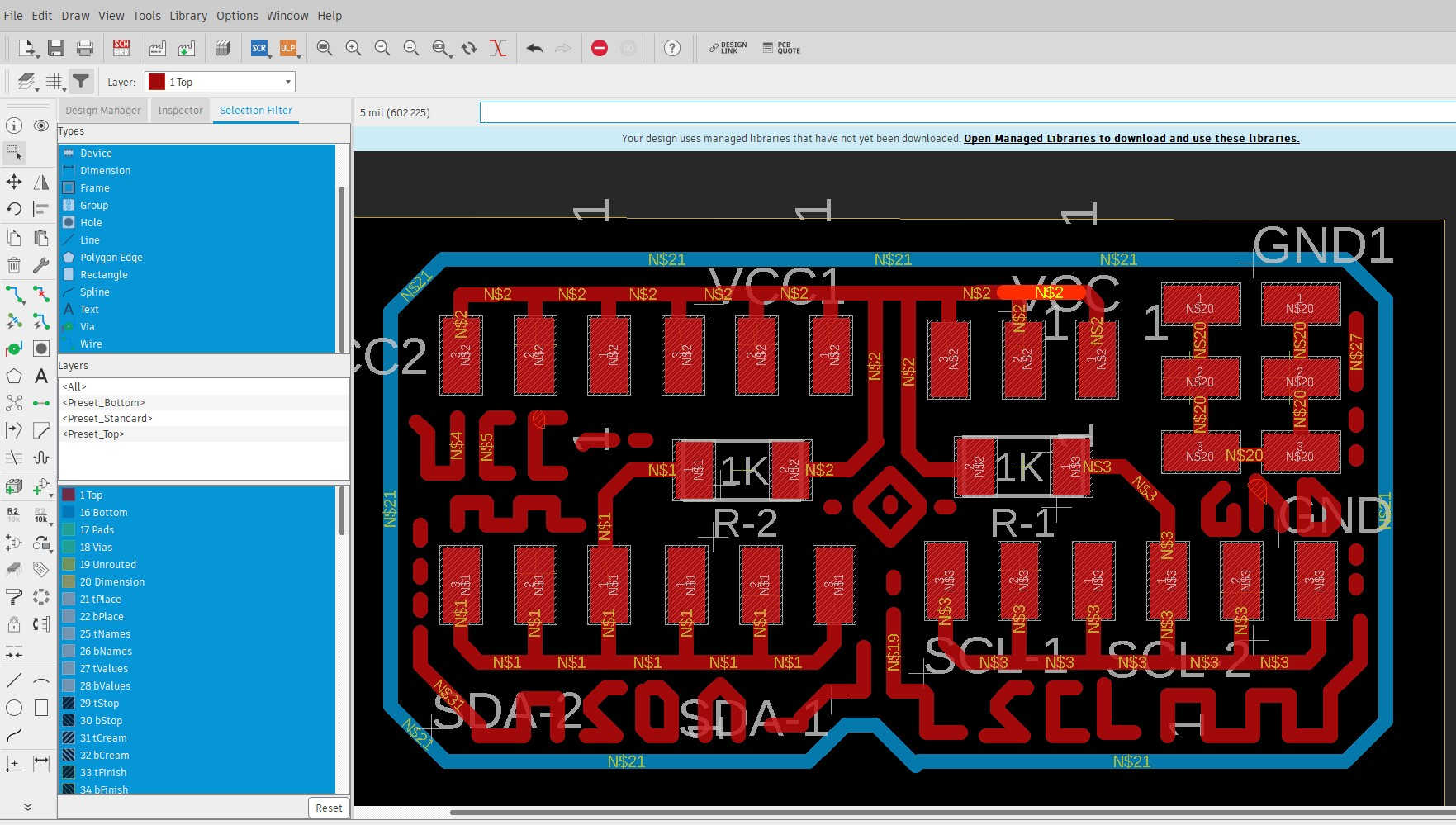
(10) The final board.
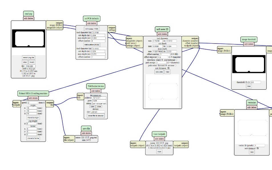
(11) Once I generated the PNG files, I followed the same workflow as in Electronic Production Week, Electronic Design and Output Devices. I used Mods to generate the manufacturing codes.
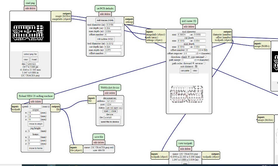
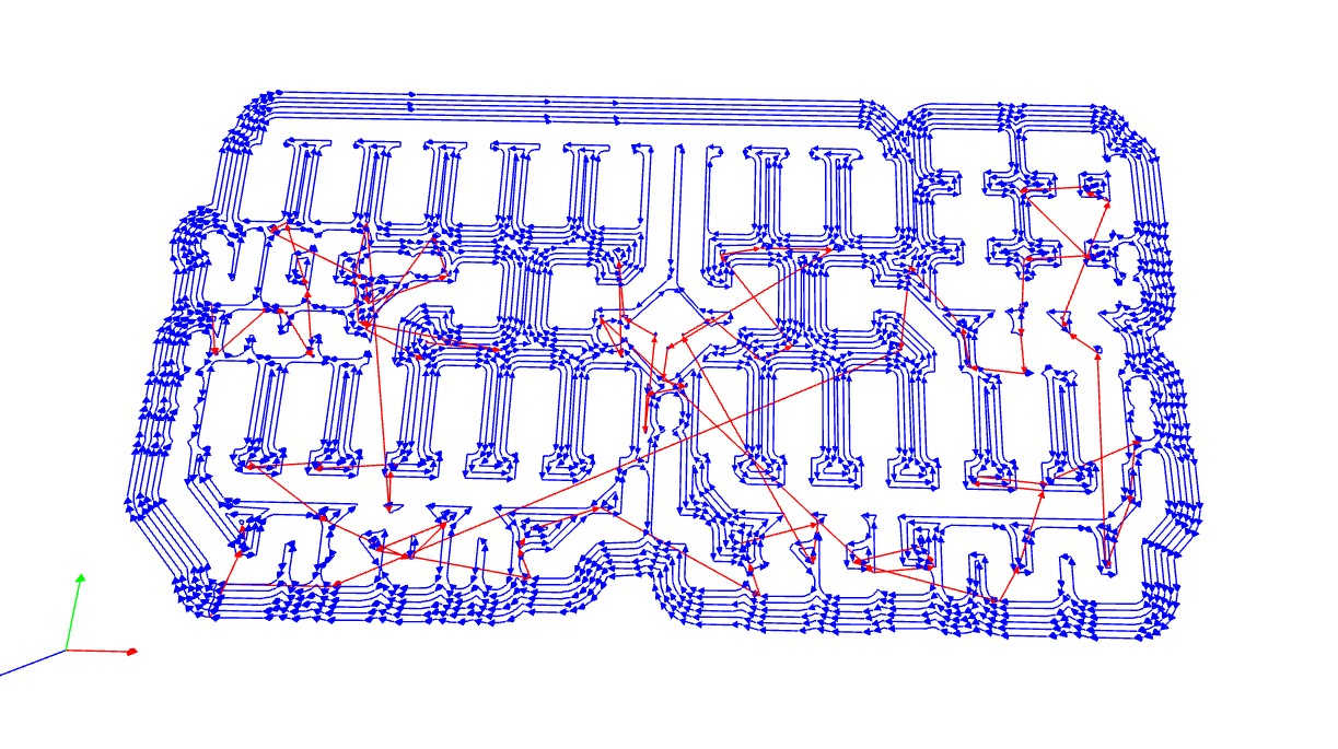
(12) Settings for contour cutting:

(13) Problems and how to solve them:
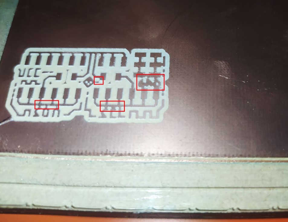
(14) After machining the traces I had some minor errors, I put the texts of each group of outputs, but I forgot to give them the correct separation, so some traces were joined. I considered re-machining the board but tried to fix it with a utility knife and the part was saved, after a couple of continuity tests I went on to contour cut.
Board and components ready to solder:
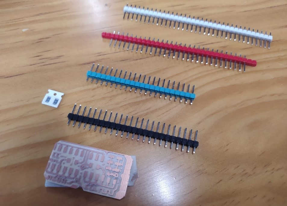
(15) It is a very simple and small board, but it is beautiful to look at, the colors are inspired by the Mexican flag.
(16) A moment of great satisfaction is making the corresponding connections:

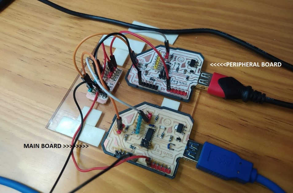
(17) Once the hardware was ready, I started with the programming phase, for this I focused on two small projects:
• Turn on and off a led of the peripheral board from the serial monitor of the main board.
• Control the peripheral board's RGB lighting from the main board's serial monitor.
I am very grateful for the documentation of Luis Hernández and Joris Lam since they were very useful for me to understand the programming process.
http://archive.fabacademy.org/archives/2017/fablabamsterdam/students/60/15_communications.html
http://fabacademy.org/2020/labs/ciudadmexico/students/luis-hernandez/14_1.html
![]()
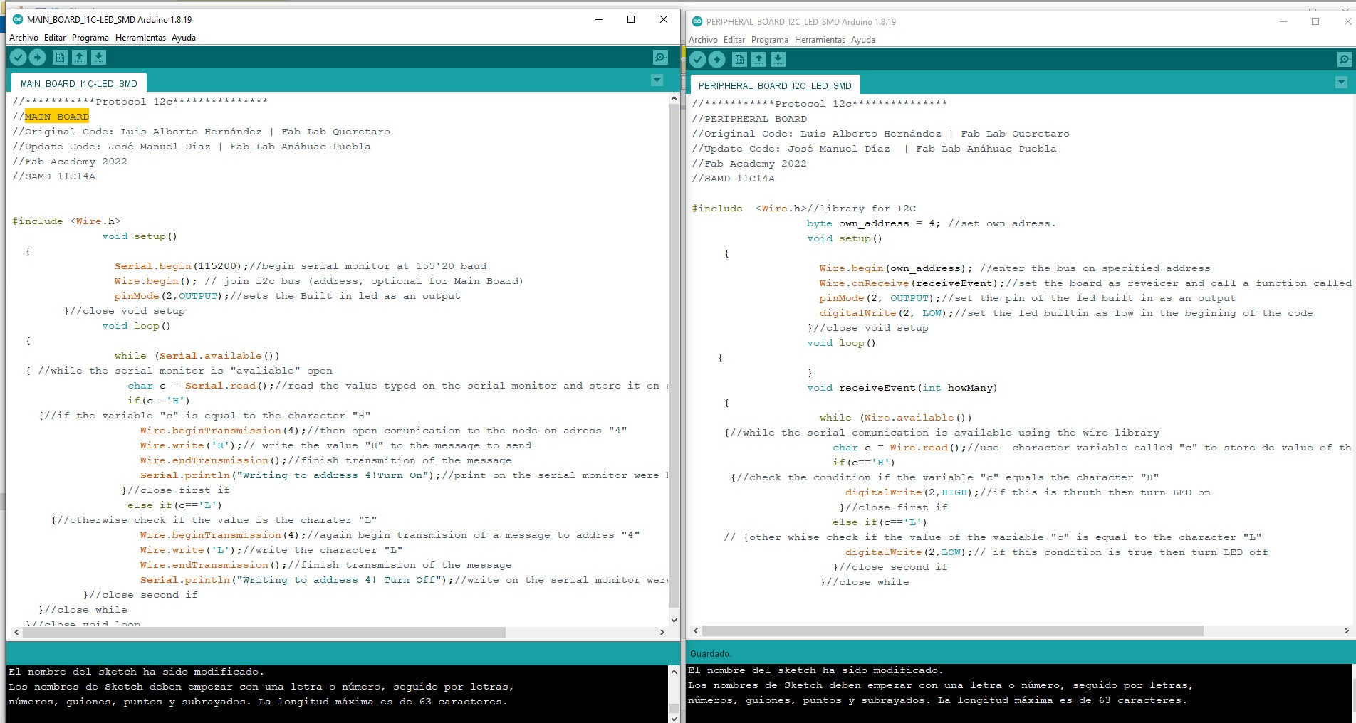
First exercise “Turn on an SMD LED”
As expected for this type of communication, each board is required to be programmed with certain specific instructions.
After studying the codes of Luís and Joris (and reviewing again some videos on Youtube 😉) I started with this task. I used Luis's code as a base, and I made notes that helped me understand what each line of code does.)
This was the result of the first exercise.
![]()
//***********Protocol 12c***************
//MAIN BOARD
//Original Code: Luis Alberto Hernández | Fab Lab Queretaro
//Update Code: José Manuel Díaz | Fab Lab Anáhuac Puebla
//Fab Academy 2022
//SAMD 11C14A
#include <Wire.h>
void setup()
{
Serial.begin(115200);//begin serial monitor at 155'20 baud
Wire.begin(); // join i2c bus (address, optional for Main Board)
pinMode(2,OUTPUT);//sets the Built in led as an output
}//close void setup
void loop()
{
while (Serial.available())
{ //while the serial monitor is "avaliable" open
char c = Serial.read();//read the value typed on the serial monitor and store it on a character variable called "c"
if(c=='H')
{//if the variable "c" is equal to the character "H"
Wire.beginTransmission(4);//then open comunication to the node on adress "4"
Wire.write('H');// write the value "H" to the message to send
Wire.endTransmission();//finish transmition of the message
Serial.println("Writing to address 4!Turn On");//print on the serial monitor were have the message sent to
}//close first if
else if(c=='L')
{//otherwise check if the value is the charater "L"
Wire.beginTransmission(4);//again begin transmision of a message to addres "4"
Wire.write('L');//write the character "L"
Wire.endTransmission();//finish transmision of the message
Serial.println("Writing to address 4! Turn Off");//write on the serial monitor were just sent the message
}//close second if
}//close while
}//close void loop
![]()
//***********Protocol 12c***************
//PERIPHERAL BOARD
//Original Code: Luis Alberto Hernández | Fab Lab Queretaro
//Update Code: José Manuel Díaz | Fab Lab Anáhuac Puebla
//Fab Academy 2022
//SAMD 11C14A
#include <Wire.h>//library for I2C
byte own_address = 4; //set own adress.
void setup()
{
Wire.begin(own_address); //enter the bus on specified address
Wire.onReceive(receiveEvent);//set the board as reveicer and call a function called receiveEvent
pinMode(2, OUTPUT);//set the pin of the led built in as an output
digitalWrite(2, LOW);//set the led builtin as low in the begining of the code
}//close void setup
void loop()
{
}
void receiveEvent(int howMany)
{
while (Wire.available())
{//while the serial comunication is available using the wire library
char c = Wire.read();//use character variable called "c" to store de value of the message sent from the host
if(c=='H')
{//check the condition if the variable "c" equals the character "H"
digitalWrite(2,HIGH);//if this is thruth then turn LED on
}//close first if
else if(c=='L')
// {other whise check if the value of the variable "c" is equal to the character "L"
digitalWrite(2,LOW);// if this condition is true then turn LED off
}//close second if
}//close while
(VIDEO 1)
*****
![]()
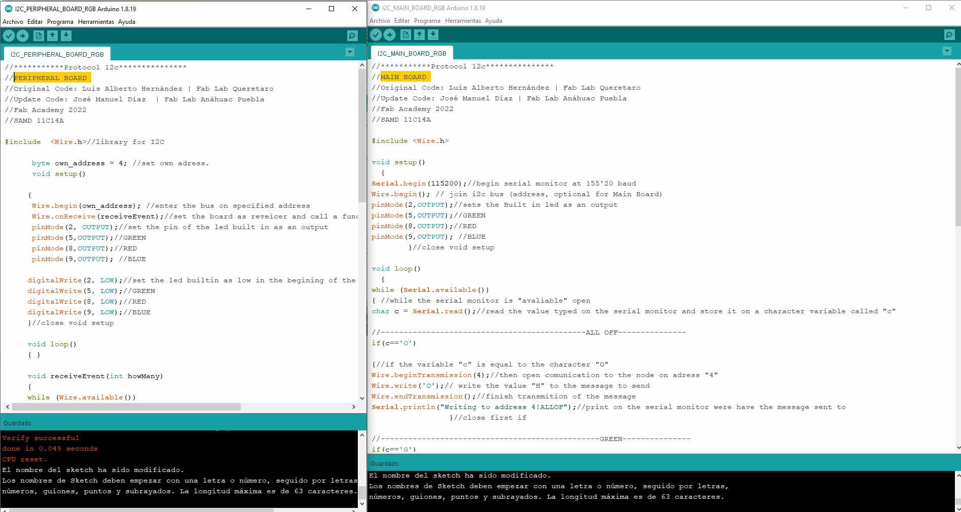
(18) Turn on one RGB LED and one SMD LED (Main Board to Peripheral Board)
After succeeding in the first exercise I wanted to increase the degree of difficulty of the program a bit, so I added an RGB SMD LED to the peripheral board, in order to control its behavior from the main board's serial monitor.
For this I had to declare the new output pins and assign the corresponding "IF" so that when sending a character from the main serial monitor, the peripheral board would turn on or turn off the connected devices.
I added some lines to break up each task as I was getting a bit confused at first.
After a few hours of testing, I managed to get it to work 😊
Here the result:
![]()
//***********Protocol 12c***************
//MAIN BOARD
//Original Code: Luis Alberto Hernández | Fab Lab Queretaro
//Update Code: José Manuel Díaz | Fab Lab Anáhuac Puebla
//Fab Academy 2022
//SAMD 11C14A
#include <Wire.h>
void setup()
{
Serial.begin(115200);//begin serial monitor at 155'20 baud
Wire.begin(); // join i2c bus (address, optional for Main Board)
pinMode(2,OUTPUT);//sets the Built in led as an output
pinMode(5,OUTPUT);//GREEN
pinMode(8,OUTPUT);//RED
pinMode(9,OUTPUT); //BLUE
}//close void setup
void loop()
{
while (Serial.available())
{ //while the serial monitor is "avaliable" open
char c = Serial.read();//read the value typed on the serial monitor and store it on a character variable called "c"
//---------------------------------------------ALL OFF---------------
if(c=='O')
{//if the variable "c" is equal to the character "O"
Wire.beginTransmission(4);//then open comunication to the node on adress "4"
Wire.write('O');// write the value "H" to the message to send
Wire.endTransmission();//finish transmition of the message
Serial.println("Writing to address 4!ALLOF");//print on the serial monitor were have the message sent to
}//close first if
//------------------------------------------------GREEN---------------
if(c=='G')
{//if the variable "c" is equal to the character "G"
Wire.beginTransmission(4);//then open comunication to the node on adress "4"
Wire.write('G');// write the value "G" to the message to send
Wire.endTransmission();//finish transmition of the message
Serial.println("Writing to address 4!GREEN");//print on the serial monitor were have the message sent to
}//close first if
//------------------------------------------------RED---------------
if(c=='R')
{//if the variable "c" is equal to the character "R"
Wire.beginTransmission(4);//then open comunication to the node on adress "4"
Wire.write('R');// write the value "H" to the message to send
Wire.endTransmission();//finish transmition of the message
Serial.println("Writing to address 4!RED");//print on the serial monitor were have the message sent to
}//close first if
//-----------------------------------------------BLUE---------------
if(c=='B')
{//if the variable "c" is equal to the character "B"
Wire.beginTransmission(4);//then open comunication to the node on adress "4"
Wire.write('B');// write the value "B" to the message to send
Wire.endTransmission();//finish transmition of the message
Serial.println("Writing to address 4!BLUE");//print on the serial monitor were have the message sent to
}//close first if
//------------------------------------- LED PIN#2 HIGH---------------
if(c=='H')
{//if the variable "c" is equal to the character "H"
Wire.beginTransmission(4);//then open comunication to the node on adress "4"
Wire.write('H');// write the value "H" to the message to send
Wire.endTransmission();//finish transmition of the message
Serial.println("Writing to address 4!Turn On Pin#2");//print on the serial monitor were have the message sent to
}//close first if
//-------------------------------------- LED PIN#2 LOW---------------
else if(c=='L')
{//otherwise check if the value is the charater "L"
Wire.beginTransmission(4);//again begin transmision of a message to addres "4"
Wire.write('L');//write the character "L"
Wire.endTransmission();//finish transmision of the message
Serial.println("Writing to address 4! Turn Off Pin #2");//write on the serial monitor were just sent the message
}//close second if
}//close while
}//close void loop
![]()
//***********Protocol 12c***************
//PERIPHERAL BOARD
//Original Code: Luis Alberto Hernández | Fab Lab Queretaro
//Update Code: José Manuel Díaz | Fab Lab Anáhuac Puebla
//Fab Academy 2022
//SAMD 11C14A
#include <Wire.h>//library for I2C
byte own_address = 4; //set own adress.
void setup()
{
Wire.begin(own_address); //enter the bus on specified address
Wire.onReceive(receiveEvent);//set the board as reveicer and call a function called receiveEvent
pinMode(2, OUTPUT);//set the pin of the led built in as an output
pinMode(5,OUTPUT);//GREEN
pinMode(8,OUTPUT);//RED
pinMode(9,OUTPUT); //BLUE
digitalWrite(2, LOW);//set the led builtin as low in the begining of the code
digitalWrite(5, LOW);//GREEN
digitalWrite(8, LOW);//RED
digitalWrite(9, LOW);//BLUE
}//close void setup
void loop()
{ }
void receiveEvent(int howMany)
{
while (Wire.available())
{//while the serial comunication is available using the wire library
char c = Wire.read();//use character variable called "c" to store de value of the message sent from the host
//------------------------------------------------ ALLOFF ----------------
if(c=='O')
{//check the condition if the variable "c" equals the character "O"
digitalWrite(2, LOW);//set the led builtin as low in the begining of the code
digitalWrite(5, LOW);//GREEN
digitalWrite(8, LOW);//RED
digitalWrite(9, LOW);//BLUE
digitalWrite(2,LOW);//Led PIN #2 LOW
}//close first if
//------------------------------------------------ GREEN ----------------
if(c=='G')
{//check the condition if the variable "c" equals the character "G"
digitalWrite(5, HIGH);//GREEN
}//close if
//------------------------------------------------ RED ----------------
if(c=='R')
{//check the condition if the variable "c" equals the character "R"
digitalWrite(8, HIGH);//RED
}//close if
//------------------------------------------------ BLUE ----------------
if(c=='B')
{//check the condition if the variable "c" equals the character "B"
digitalWrite(9, HIGH);//BLUE
}//close if
//-------------------------------------- LED PIN#2 HIGH ----------------
if(c=='H')
{//check the condition if the variable "c" equals the character "H"
digitalWrite(2,HIGH);//if this is thruth then turn LED on
}//close if
//--------------------------------------- LED PIN#2 LOW ----------------
else if(c=='L')
// {other whise check if the value of the variable "c" is equal to the character "L"
digitalWrite(2,LOW);// if this condition is true then turn LED off
}//close if
}//close while
(VIDEO 2)
![]()
![]()
(19) Here you can download all the files generated in this assignment:
• JOSAMD 1.0
• I2C communication board
• Code | Turn on and off a led on the peripheral board from the serial monitor on the main board.
• Code | Control the peripheral board's RGB lighting from the main board's serial monitor.
![]()
Copyright 2022 Jose Manuel Diaz Bello