
**************************************************************************
Use the test equipment in your lab to observe the operation of a microcontroller circuit board (in minimum, check operating voltage on the board with multimeter or voltmeter and use oscilloscope to check noise of operating voltage and interpret a data signal)
Document your work to the group work page and reflect on your individual page what you learned
Individual assignment:
Redraw one of the echo hello-world boards or something equivalent, add (at least) a button and LED (with current-limiting resistor) or equivalent input and output, check the design rules, make it, test it. Optionally, simulate its operation.
*************************************************************************
(1) Welcome to the electronic design week, a very interesting challenge for those students who do not have a background in electronics. Without a doubt, this is one of the assignments that I have enjoyed the most.
The first thing I did was review all the documentation available on the assignment page
http://academy.cba.mit.edu/classes/electronics_design/index.html
In addition to looking for some resources on the internet about components, software for circuit design and test equipment. At the same time I am taking an online course: Arduino, electronics and C programming from scratch, which has helped me a lot to understand important terms and make simple circuits with Arduino, practicing this in a simulator like Thinkercad is a great option to gain confidence and know in broad strokes the operation of microprocessors and input and output components.
https://www.udemy.com/course/arduino-from-scratch-with-tinkercad/
(2) After doing some research on design software, I decided to work on this assignment with Eagle for two reasons:
• The extensive documentation and large community that exists on the internet.
• The agreement of our university to use all Autodesk packages freely.
Another very useful resource is this tutorial created by Anna Kaziunas France and updated by Eduardo Chamorro
http://pub.fabcloud.io/tutorials/week06_electronic_design/eagle_english.html
It's definitely a must-have guide if you decide to use Eagle for this assignment as it covers everything from how to install Eagle, understand the schematic and board interfaces, add new components, connect them, export trace and slice files, and much more.
Once I have consulted these materials, it is time to start the action.
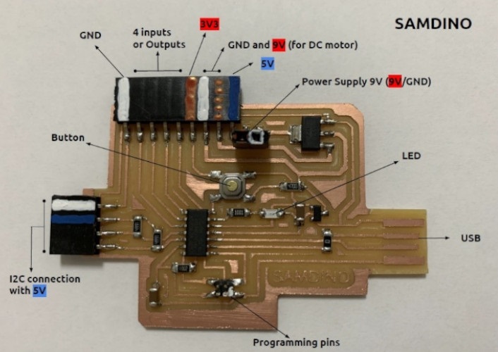
(3) The first step is to choose which echo hello-world board to redesign and redraw, as my programmer was a SAMD11C SDW, I decided to work with a board that used this same microprocessor, so I decided to take up one of the most complete projects I have seen at Academy: Samdino by Adrián Torres from Fab Lab Leon
http://fabacademy.org/2020/labs/leon/students/adrian-torres/samdino.html
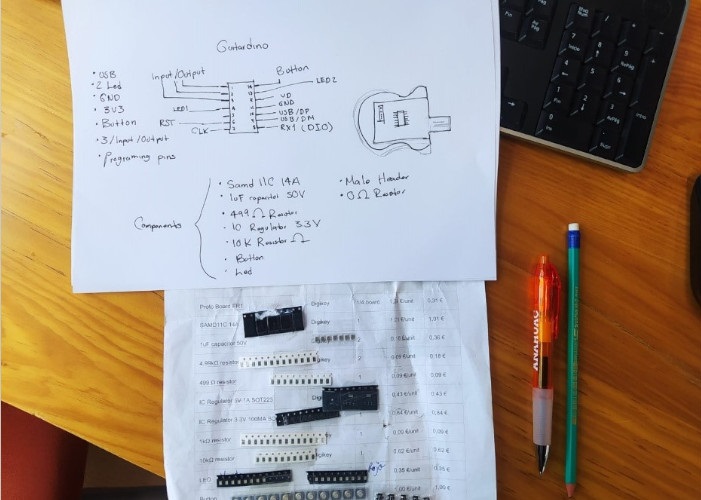
(4) For this assignment I will make a slightly more minimalist version with the following elements.
•USB
• 2 LEDs
•GND
• 3V3
•Button
• 3 inputs or outputs
• Programming pins
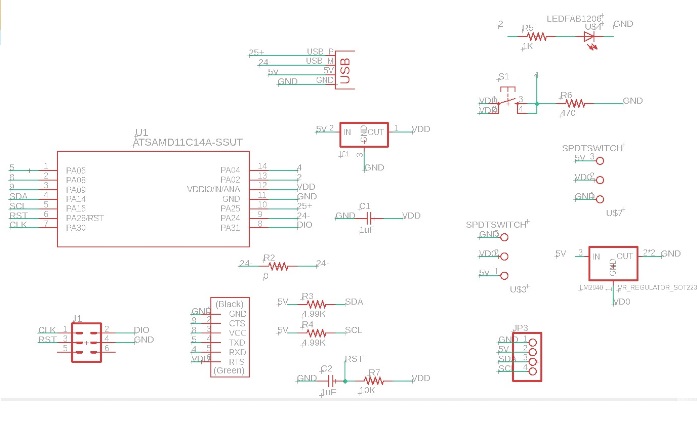
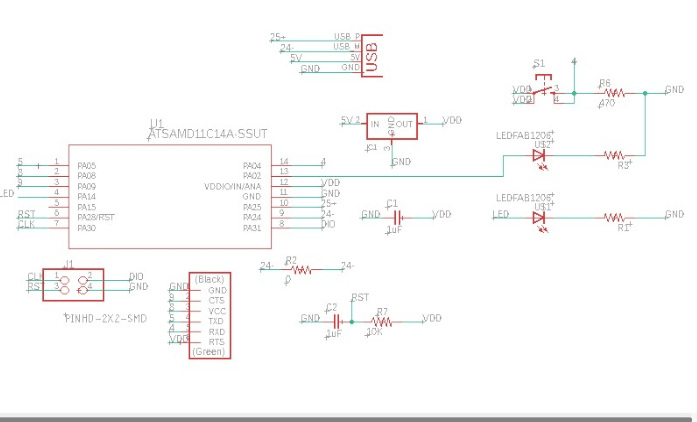
(5) I will use Adrián's diagram as a base and from there I will adjust the components for my Guitarduino. (Sketch, components and first design ideas)
(6) Special thanks to my Instructor Iván for teaching Eagle electronic design and management.
This is the original layout and board of the Samdino, which will be the starting point for the birth of the Guitardino.
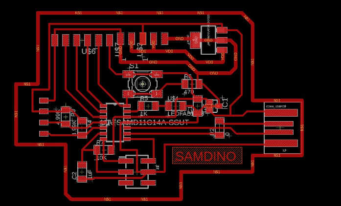
(7) So the next step was to discard those elements that will not be part of the design and add the new components.
(8) After debugging
(9) New leds and their respective limiting resistors.
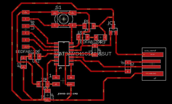
(10) Here begins the best part, reorient and reposition the components in order to obtain short clues and give the board personality. This process took me approximately 4 hours between positioning and repositioning.
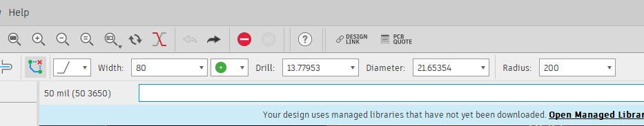
(11) It is very important that these parameters are configured according to the characterization made in the assignment of electronic production.
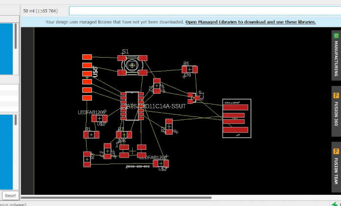
(12) At one point I also wanted to experiment with the autorouter option, but it didn't work out as expected so I kept trying until I got it, with a couple of tips from Iván: how to use a bridge for USB-M, for that use a resistor with a value of 0
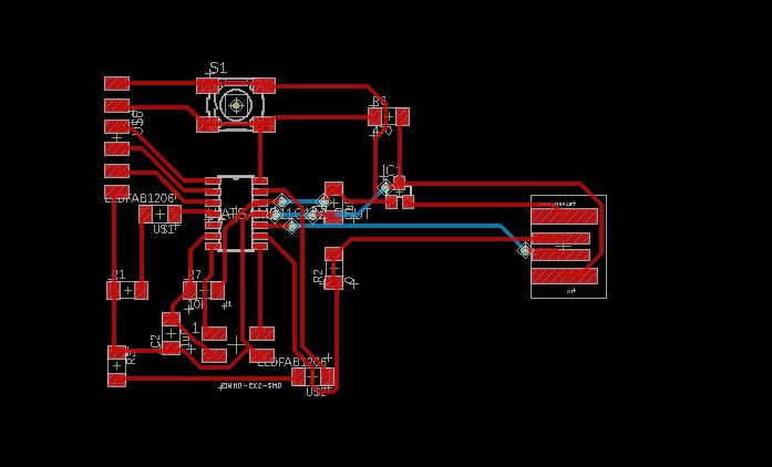
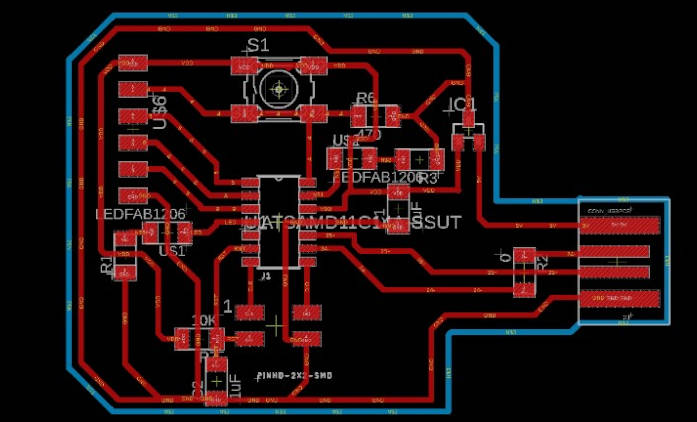
(13) Here the final result (even without contour delimitation)
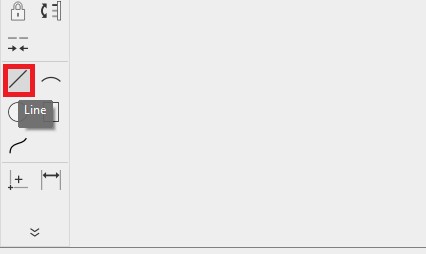
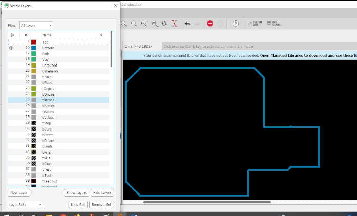
(14) At this point I started to delimit the shape of the guitar (at least an approximation) because I want to give the final appearance with a casing made with 3D printing. The next step was to choose the bottom layer to trace the cut contour of the Guitardino
(15) For this step I used the line tool
(16) This was the result:
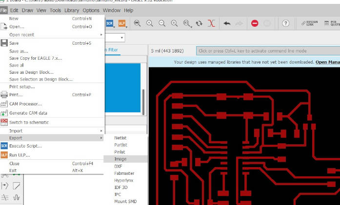
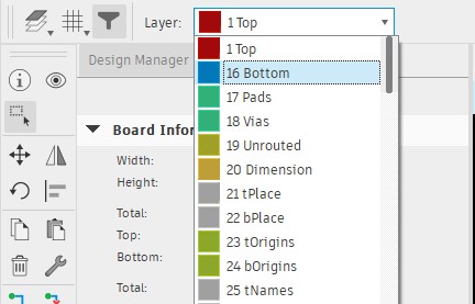
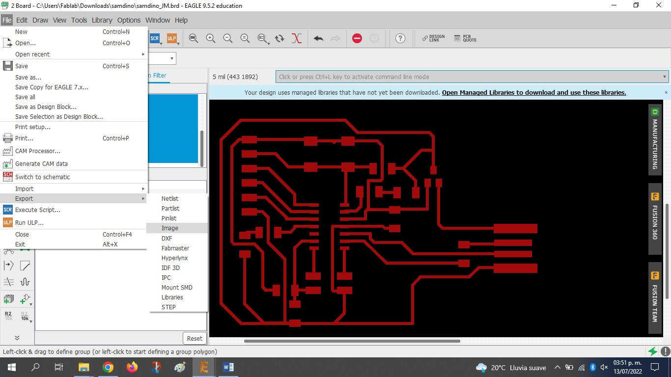
(17) It is time to export the PNG files, one for the traces and another for the contour cut, for this I used the layer manager and the export tool.
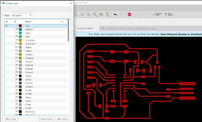
First I generated the traces PNG so from the layer manager I turned off all layers except the traces you can use the HIDE LAYERS tool
(18) FILE> export> IMAGE
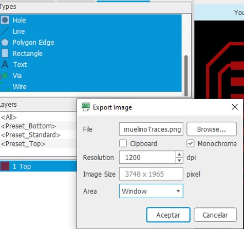
(19) The following parameters are important to obtain good results when machining the board.
RESOLUTION: 1200 DPI
MONOCHROME: OK
AREA: WINDOW
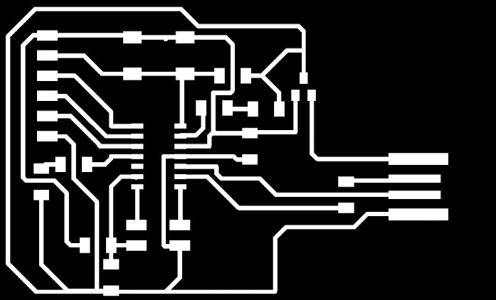
(20) The beautiful result:
(21) We repeat the process for the BOTTOM layer
(22) For contours there is an additional recommended step: open from an image editor and fill in the interior of the contour, in my case use PAINT for this step.
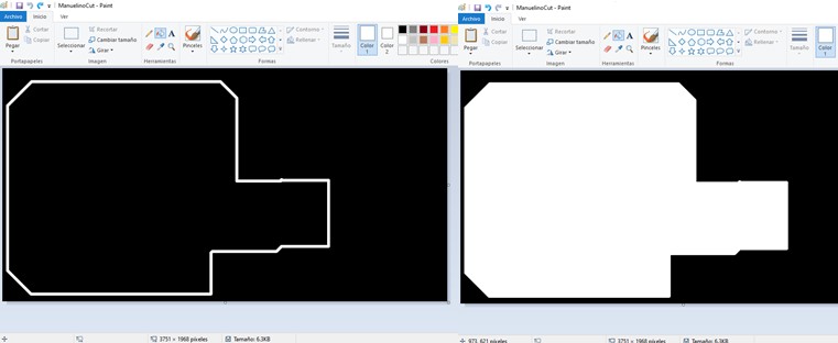
(23) Before and after editing.
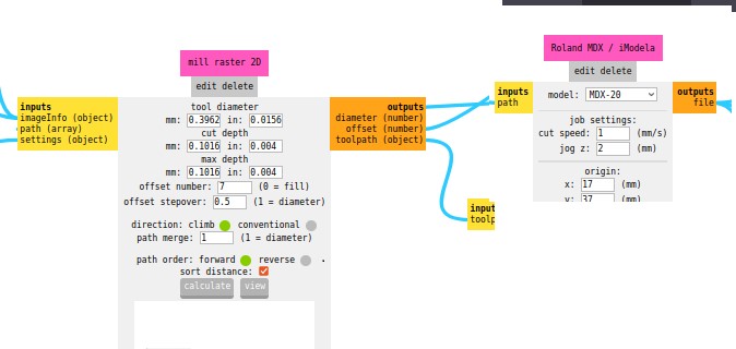
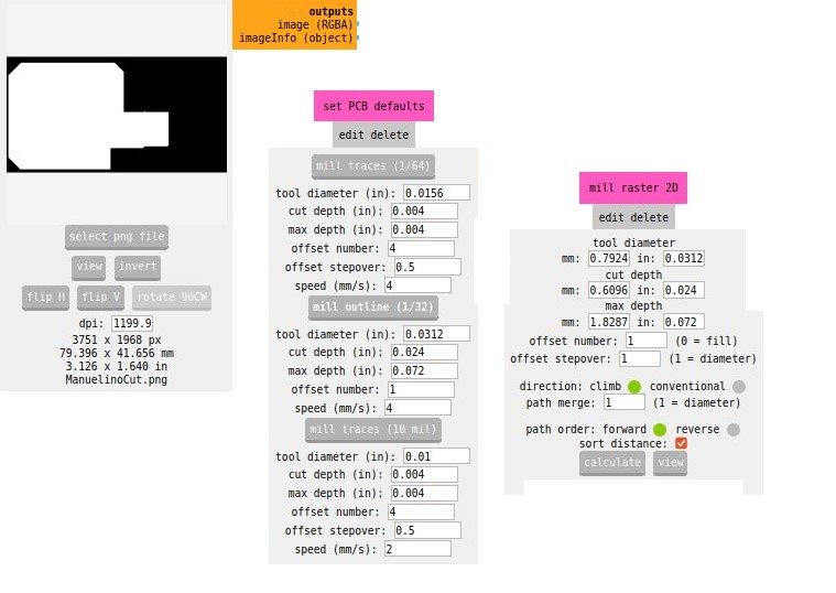
The following steps were carried out in FAB LAB CIUDAD DE MEXICO, so use the parameters that were characterized for your CNC milling machine. In electronic production week I also use MODS to generate the G-codes so I'm already familiar with this workflow.
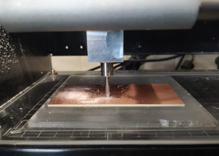
Machine: Roland Modela MDX 20
Technical specifications:
• Table: 220mm x 160mm
• Operating Area: 203mm x 152
• Modeling Functions:
Maximum resolution: 0.00625mm/step
• Speed: 0.1 to 15mm/sec
TRACES:
(24) The machining process:
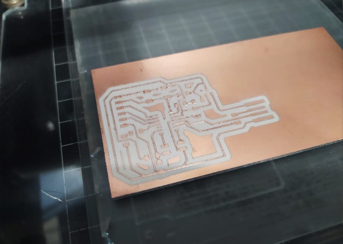
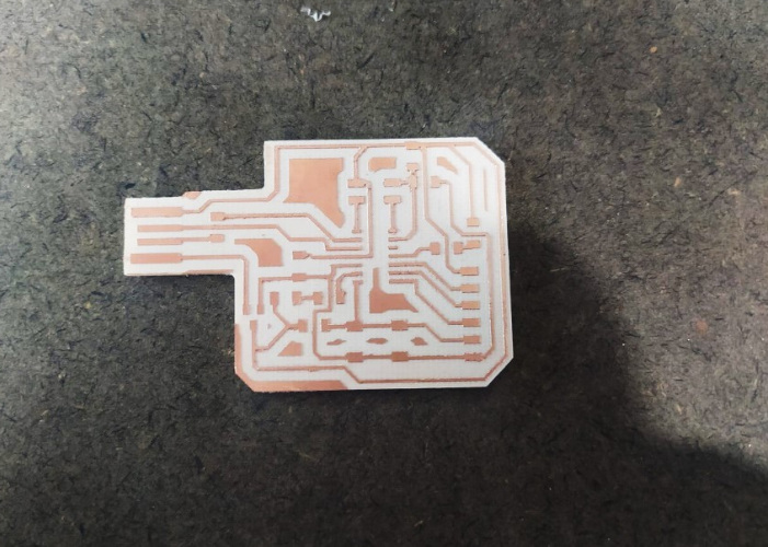
(25) The result:
(26) I continued with the cutting of the board.
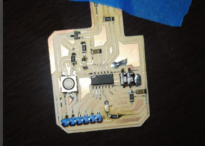
(27) Board ready for mounting components.
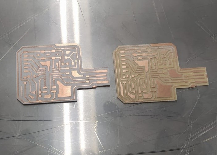
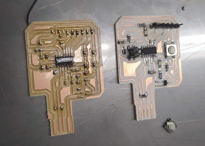
(28) As in the electronic production assignment, I will manufacture two boards in anticipation of some fatal error in the assembly of the components. The Twins:
(29) Component assembly order:
• SAMD 11C
• IC Regulator 3.3V
• Resistors
• LED
• 1uF capacitor
• Connector Headers 4POS
• Male 1 row horizontal header
•Button
(29) Video welding
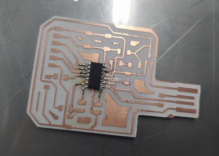
(30) Fortunately, the two twins had a successful assembly of all the components, with the second exercise I applied tin to all the joining points and then I assembled the components with the help of the soldering iron, the time was considerably less, although it can also have an impact on That is the experience you are taking when welding.
Board 01 = 130 min
Board 02 =50min
(31) Before starting with the programming of the programmer we need to verify:
• Continuity of the tracks according to the design
• The correct location and polarity of components
• Tracks joined by welding, if they exist, correct their position.
(32) Now it is time to program the board, for this I will use my SDW11 programmer, which I made in the electronic production assignment.
http://pub.fabcloud.io/programmers/programmer-swd-d11c/ibom/
For this process we need:
1. EDBG latest version, you can download it from here.
https://taradov.com/bin/edbg/
Select the corresponding operating system and version.
2. Bootloader (it will allow us to program the board from the Arduino IDE)
You can download the latest version here.
https://github.com/qbolsee/ArduinoCore-fab-sam/blob/master/bootloaders/zero/binaries/sam_ba_SAMD11C14A.bin
All of the above should be in the same folder.
3.SWD-D11C programmer
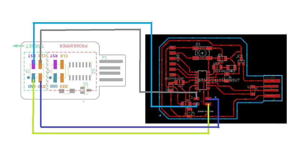
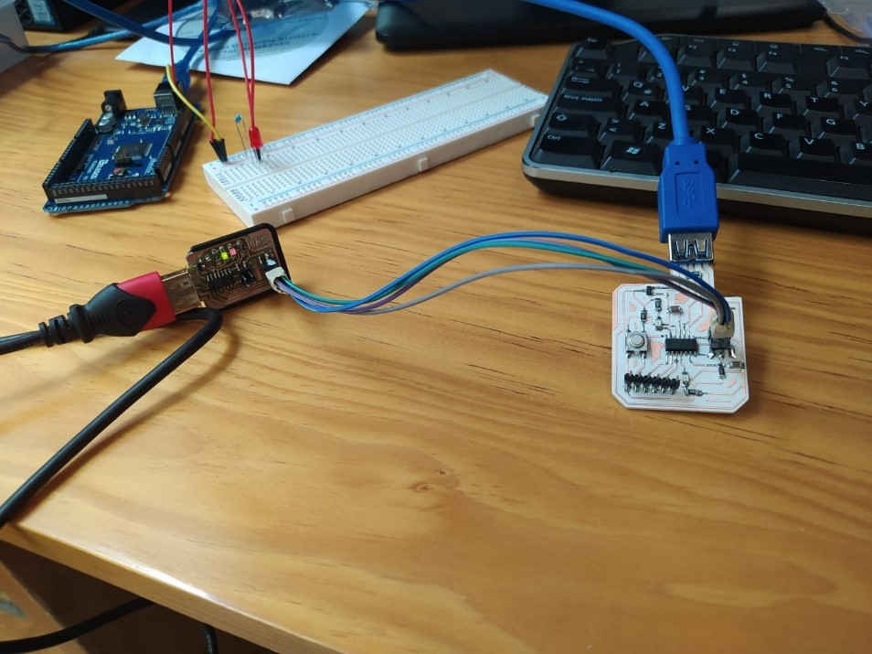
4. If like me you use a SWD programmer you will only need a cable made with 4 female-female jumpers to communicate the programmer with the Guitardino.
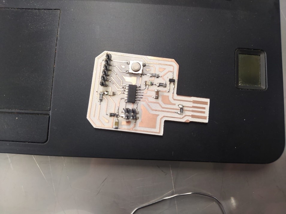
5. Lastly, we need two USB extension cables. Once the connections of the programmer and the Guitardino are made, they look like this.
(33) The SDW programmer must be connected via USB to the PC and the Guitardino must be connected to a different power supply, in my case a 5V eliminator.
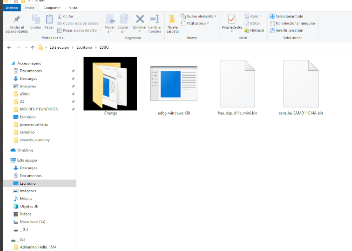
(34) This is what the folder with the corresponding files looks like:
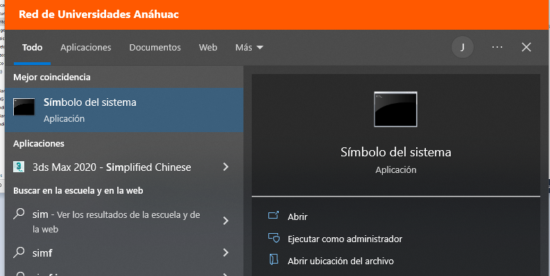
(35) We run the command prompt
(36) We open the location of our folder:
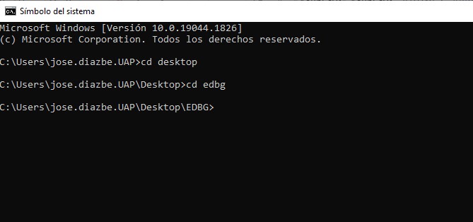
(37) We execute the command
edbg-windows-r38.exe -ebpv -t samd11 -f sam_ba_SAMD11C14A.bin
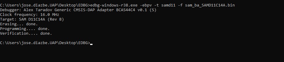
(38) If you have a version other than 38, you must change the corresponding version number: R38, R39, R40...
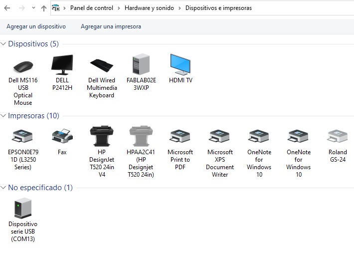
When connecting the board to the computer, the system should recognize it as an out-of-the-box device (COM13):
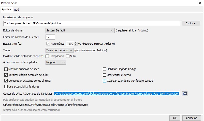
(39) From the Arduino IDE we need to do some extra steps before we can program our board. First we must add the following link in the additional card manager:
File > Preferences
https://raw.githubusercontent.com/qbolsee/ArduinoCore-fab-sam/master/json/package_Fab_SAM_index.json
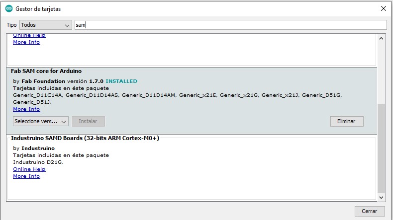
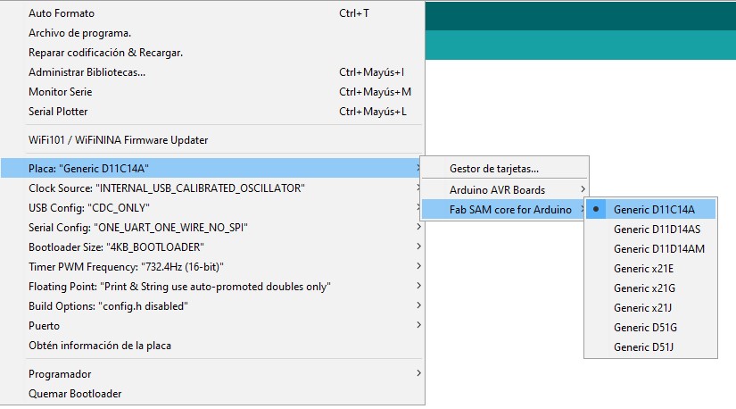
(40) Then we must download Fab SAM core for Arduino
Tools > Plate > Plate Manager
(41) We choose the Generic D11C14A Microprocessor
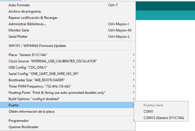
(42) And we choose the corresponding port.
(43) To test the Guitardino I will use an authorship code from Adrián Torres
-Arduino Hello Button
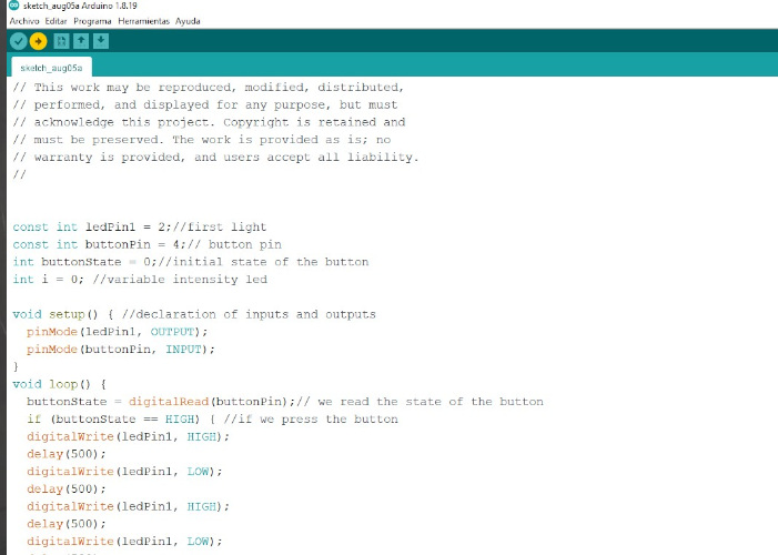
(44) You can download the code here:
http://fabacademy.org/2020/labs/leon/students/adrian-torres/samdino.html
The result:
(VIDEO)
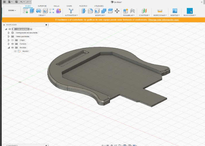
(45) I also made the casing to finish giving the style to the Guitardino.
![]()

![]()
Copyright 2022 Jose Manuel Diaz Bello