

Output Devices
****************************************
Group assignment:
Measure the power consumption of an output device
Document your work to the group work page and reflect on your individual page what you learned
Individual assignment:
Add an output device to a microcontroller board you've designed and program it to do something
**********************************************
(1) Welcome to Ouput Devices week.
This week aims to become familiar with those devices with which our microprocessor will be able to perform tasks, such as lighting LEDs, speakers, servomotors, displays, among others.
The first thing I did was review all the documentation available on the assignment page.
http://academy.cba.mit.edu/classes/output_devices/index.html
During the week of electronic production, I made the Guitardino, based on the Samdino by Adrián Torres:
http://fabacademy.org/2020/labs/leon/students/adrian-torres/samdino.html
For the input and output device assignments, I decided to make a new board that allows me to use the largest number of programmable pins, and that also has the possibility of connecting with other boards, thinking about my final project.
So with the advice of my local instructor Iván. I designed the JOSAMD 1.0 which is also based on the SAMDINO, and has an integrated LED, 4 programmable pins, plus an array of 5 GND and 5V VDD outputs.
****************************************************************************************
For this new board I used the same workflow as in electronics design week.
****************************************************************************************
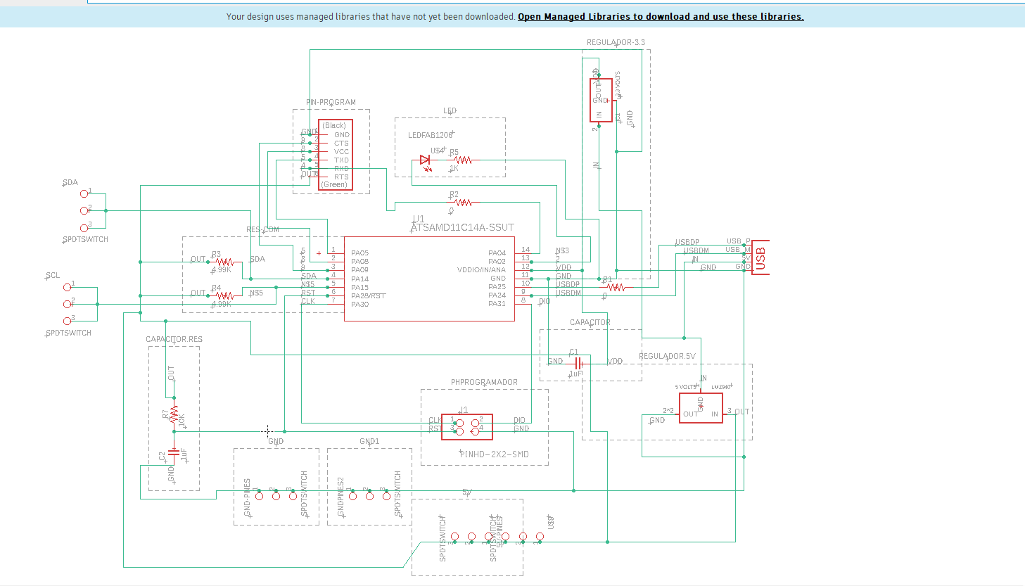
The schematic:
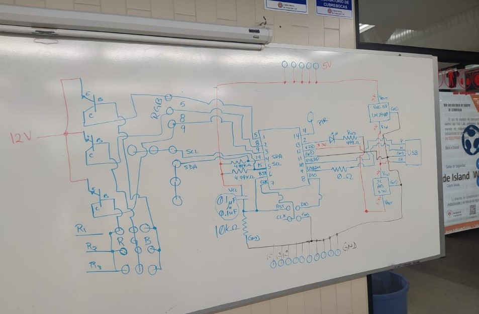
(2) Eagle schematic
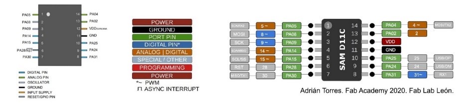
(3) SAMD 11C14A microprocessor:
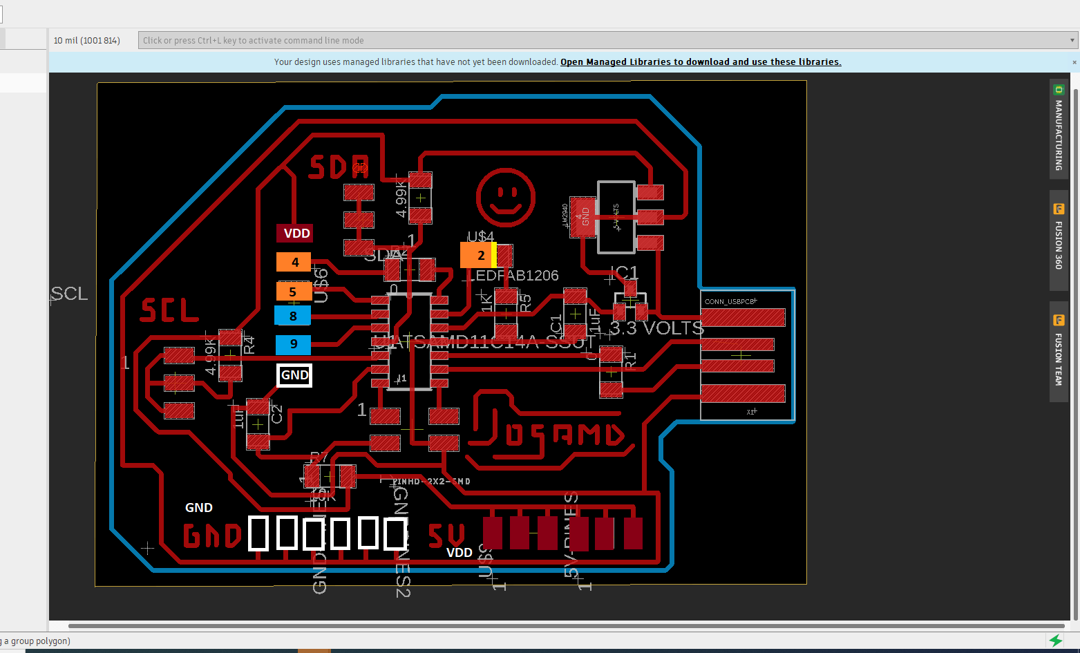
(4) Board:
(5) Trace machining and board cutting.
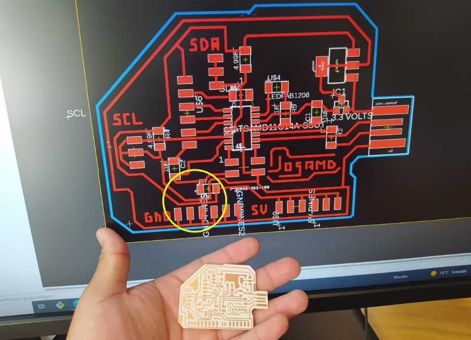
(6) The board had a small design error which I had to correct manually since two TRACE had been joined.
(7) Board ready for action:
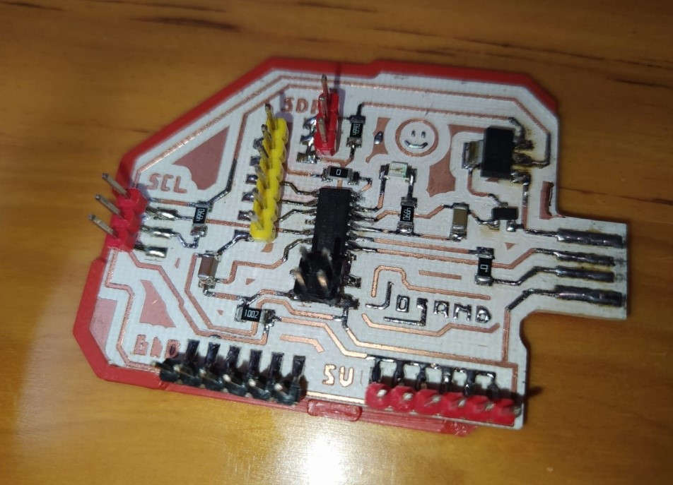
(8) Once I had assembled the components and carried out the corresponding tests, I moved on to the best part, experimenting with output devices.
For this practice I used:
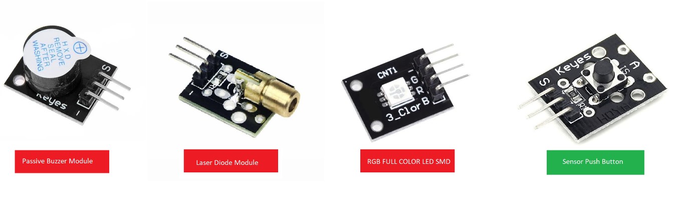
(9) (The Push button is an input device, but I'll use it to control all the outputs of this activity)
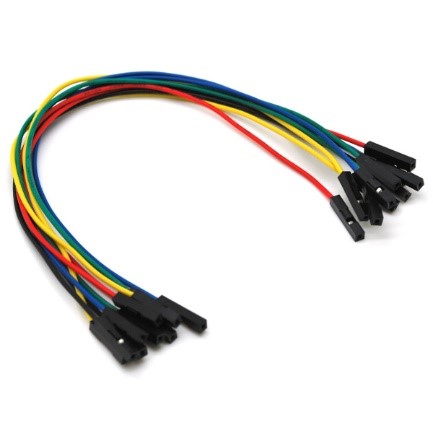
In addition to a kit of 40 jumpers
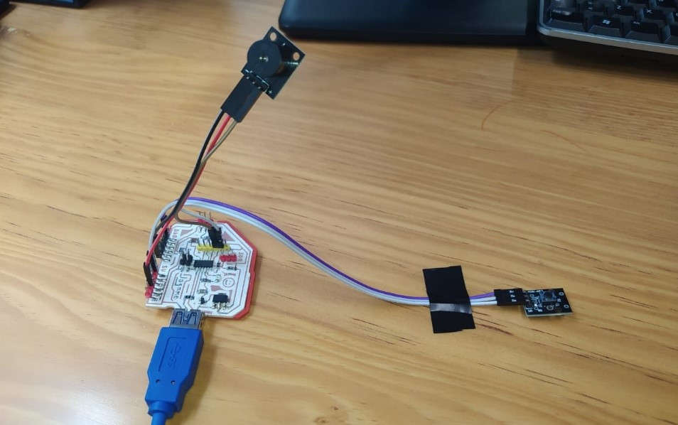
(10) Exercise 1 “Alarm system with buzzer and button"
In this first "mini project" I wanted to make an approach to an alarm system, similar to the one that exists in the windows of some shops, this for the protection of valuable merchandise.
For this I used a buzzer and a button, both modules have 3 outputs:
• Sign
• VDD(5V)
• CNG
The program is designed so that when the contact with the button is interrupted, an audible alarm emitted by the buzzer is activated.
These are the contents that I used as support to write the code:
https://arduinomodules.info/ky-006-passive-buzzer-module/
https://www.udemy.com/course/arduino-desde-cero-con-tinkercad/
Connections:
(11) Program operation:
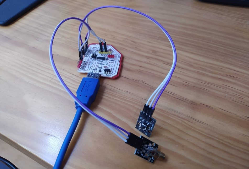
(12) Exercise 2 “Laser pointer with Diode and button”
In the KIT of sensors that we have in the FABLAB I found a laser emitter, so I also decided to do a little practice with this device, I used the button to emit light when pressed. The diode has three outputs:
• Sign
• VDD(5V)
• GND
Useful resources for the development of this exercise:
https://www.wiltronics.com.au/product/9020/arduino-compatible-laser-module/
https://www.udemy.com/course/arduino-desde-cero-con-tinkercad/
Connections:
VIDEO:
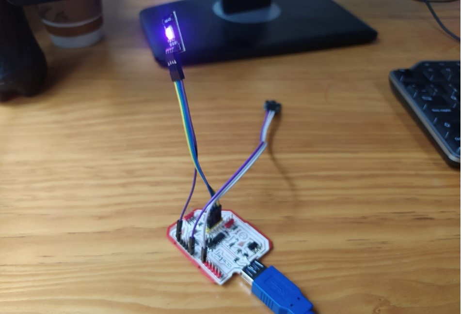
(13) Exercise 3 “RGB controlled with a button (approach to final project)”
My final project is a proposal for Montessori furniture, which offers a renewed and contemporary image of this type of furniture, since no new models or innovations have been developed in recent decades. The objective is that the design allows carrying out different activities such as studying-working, having informal reading sessions, storing teaching materials and resting. In addition, one of its attractions will be the integrated lighting, which will set the scene in which it is located, and which can be customized through an interface.
So the RGB lighting control will be a key piece in the development of the final project, which is why I have decided to start familiarizing myself with these devices and their programming.
The first thing I did was to do some research about the different methods to program the color of this diode, once this was done I made a simulation with Tinkercad to validate that the circuit will work.
(14) The RGB Leds have 4 outputs:
•RED
•BLUE
• GREEN
• Common cathode
This is what JOSAMD 1.0 looks like after making the connections.
(15) For the programming I included a variable that would allow me to store a counter, and as the counter increases, the program will assign a color for each value.
The result was the following:
Lastly, I wanted to experiment with a device in which a library had to be included, in this case I used an 8x8 LED matrix
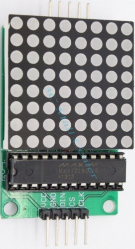
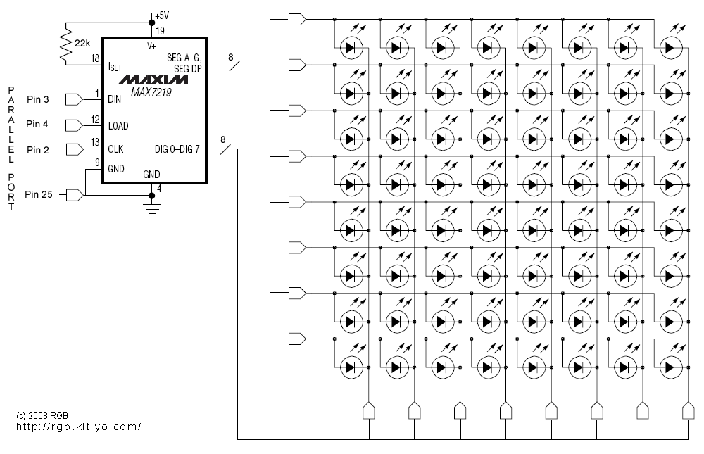
(16) Here you can find the control library as well as some programming examples.
https://github.com/shaai/Arduino_LED_matrix_sketch
To install the library you must take the following path:
Program > Include Library > Add ZIP Library
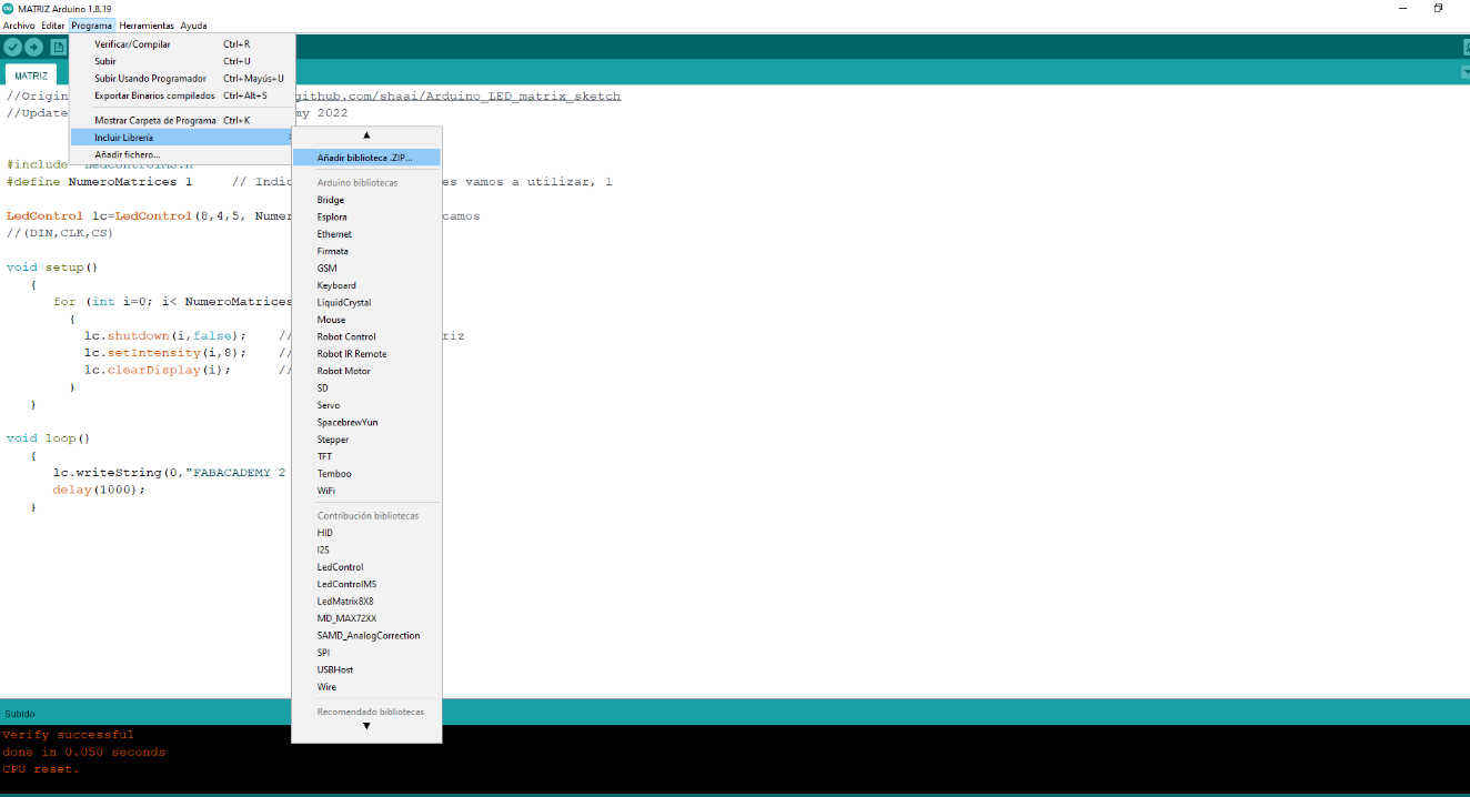
(17)
*********************
LedControl lc=LedControl(8,4,5, NumberMatrices); //
//(DIN,CLK,CS)
*********************
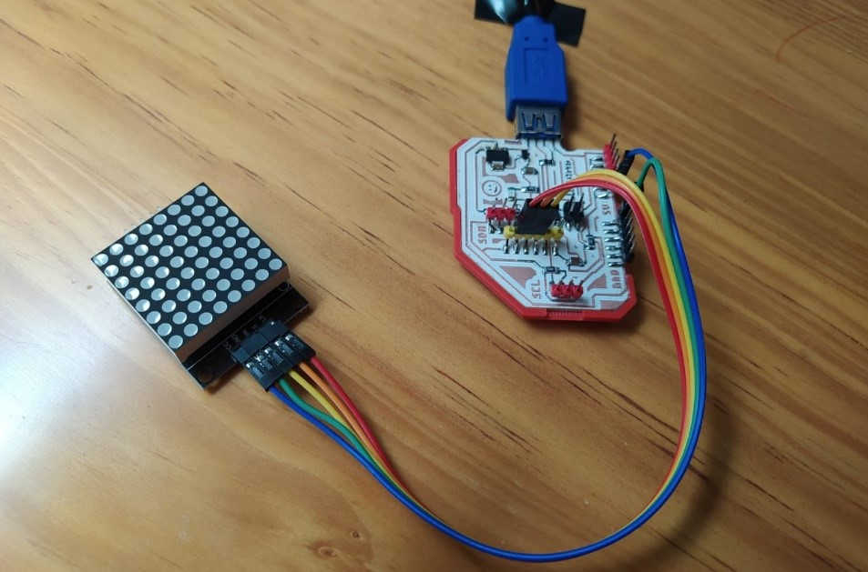
In this part of the code it is very important to verify the correct declaration of the pins connected to DIN, CLK and CS.
The connected device and boards look like this:
(18) The end result:
![]()
![]()
CODES:
JOSAMD 1.0:
![]()
Copyright 2022 Jose Manuel Diaz Bello