
*********************************************************
Electronics Production
Group assignment:
Characterize the design rules for your in-house PCB production process: document feeds, speeds, plunge rate, depth of cut (traces and outline) and tooling.
document your work (in a group or individually)
Document your work to the group work page and reflect on your individual page what you learned
Individual assignment:
Make an in-circuit programmer that includes a microcontroller by milling and stuffing the PCB, test it to verify that it works.
**********************************************************
(1) Welcome to the week of Electronic Production.
Here begins the crusade in the world of electronics, for those students who have never had contact with electronics it can be intimidating, but at the same time it means a great challenge.
After completing the group assignment, I feel very confident in making my first programmer.
You can check my group assignment here.
Let's do it! The first thing we must do is choose a programmer to manufacture, for this we must review the available documentation and download the trace and cut files.
One of the most recent programmers is the SAMD11C SDW, designed by various instructors during the Boocamp held in Oulu.
In this repository you can find all the information and credits of this programmer.
https://gitlab.fabcloud.org/pub/programmers/programmer-swd-d11c/-/commits/main
Software:
•Mods
• VPANEL
Machines:
• SRM-20 MonoFab
• Weller WE 1010
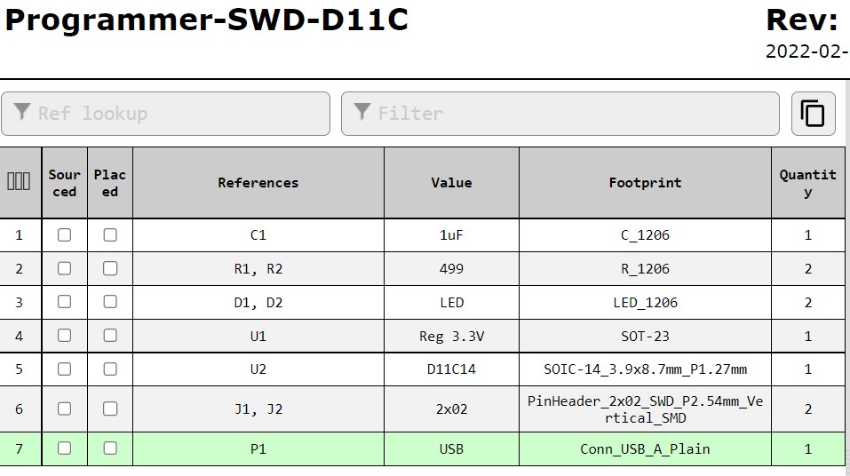
Components:
An important factor to choose any programmer is to verify that your laboratory has all the necessary components, fortunately our instructor Iván asked us weeks ago what programmer we wanted to do to have the components ready.
http://pub.fabcloud.io/programmers/programmer-swd-d11c/ibom/
(2) Here you can download the PNG files of traces and contours of the SWD-11
HERE.
http://pub.fabcloud.io/programmers/programmer-swd-d11c/
We will now continue with the workflow that was established in the group assignment.
I will work this section on Windows 10 and Mods I will work it from the Edge browser. (also works great from Firefox)
http://mods.cba.mit.edu/
Programs > Open server program > SRM20 > PCB PNG
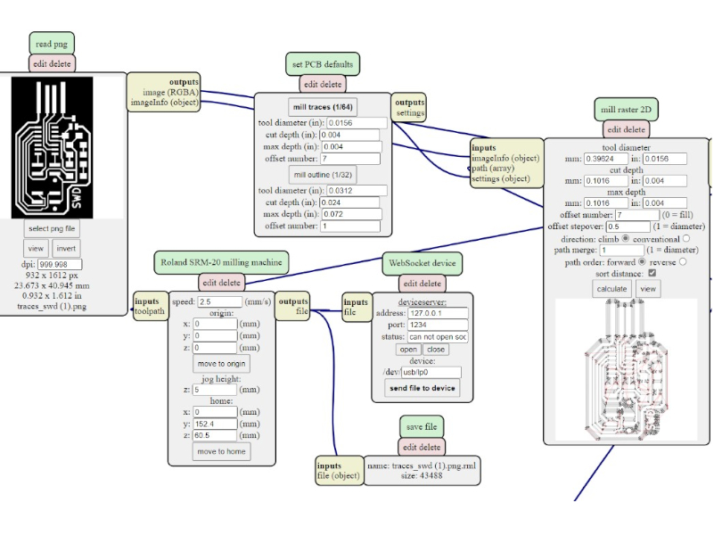
Once in mods we will start by importing the trace file, configuring with the parameters that were set in the group assignment.
Mill traces 1/64”
(3) It is important to remember that we will not be able to download the file unless we add the SAVE FILE module and connect it to the ROLAND SRM-20 MACHINE OUTPUT.
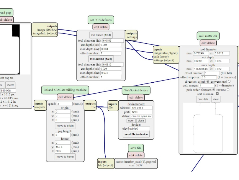
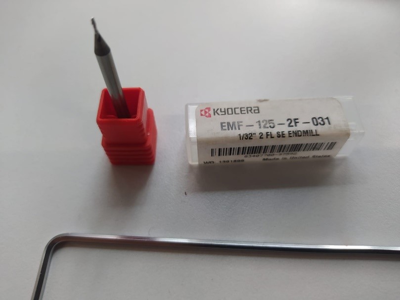
Mill Outline 1/32”
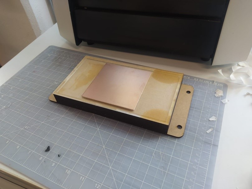
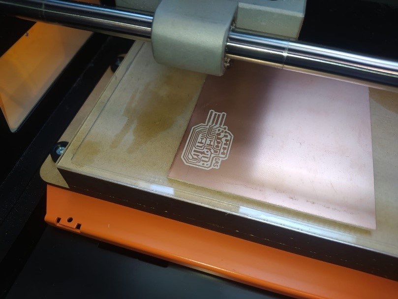
(4) I then assembled my sacrificial base, glued down the copper plate and attached the 1/64” tool.
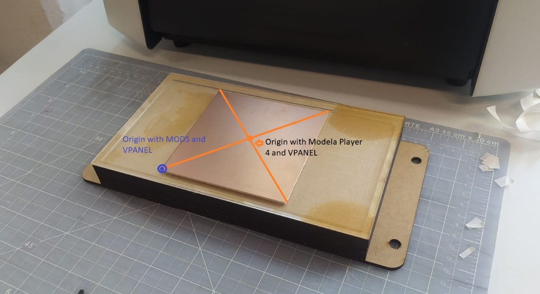
(5) From VPANEL I configured the origin in XY and Z.
There is a difference in the source configuration depending on whether we work from Modela Player 4 or MODS:
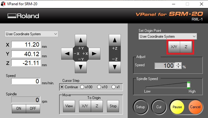
(6) These are the buttons with which I updated the origin of the 3 axes.
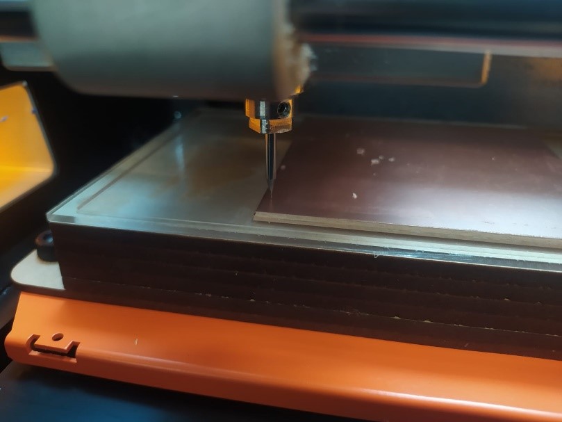
(7) Z calibration is very important, maybe 50% of the success of our work depends on it. I recommend lowering the tool almost to contact with the plate and then loosening the tool so that it makes a more precise contact, finally we tighten the tool again. This step must be done very carefully to prevent the tool from falling on the plate. We can support it with our hand or with a tool.
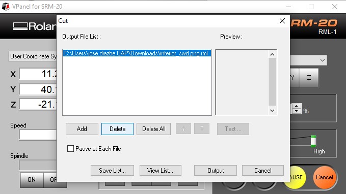
(8) Once I assigned the origin, I sent the cut from VPANEL, this is the route you must follow:
Cut > Add > Select File > Output.
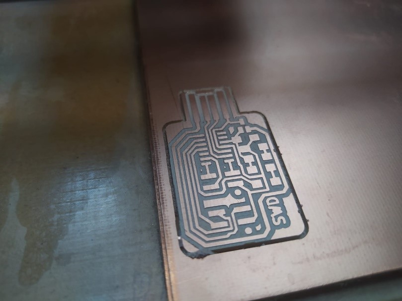
(9) Once the machine finishes the traces, we proceed to vacuum the residues.
The next step is to change the tool for a 1/32” tool, then the Z origin must be adjusted again, the X and Y origin must not be updated, otherwise our contour will be out of phase and we will have to start over .
(10) Now that we have changed the tool and updated the Z axis we can send the second file. Cut > Add > Select File > Output.
(11) Note. It is important to verify that we do not have g codes in the waiting queue, otherwise the machine will carry out all the movements of the codes that are loaded.
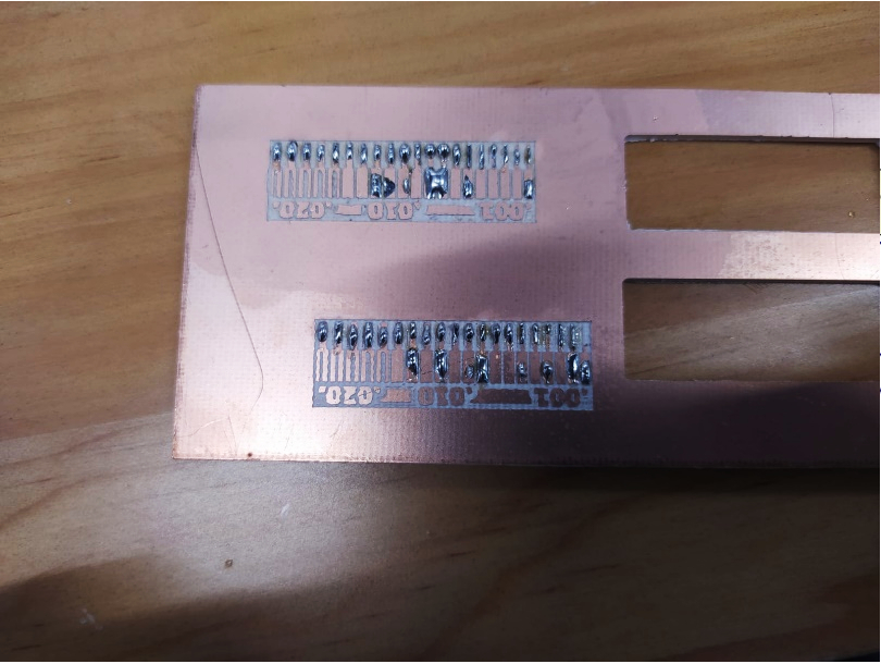
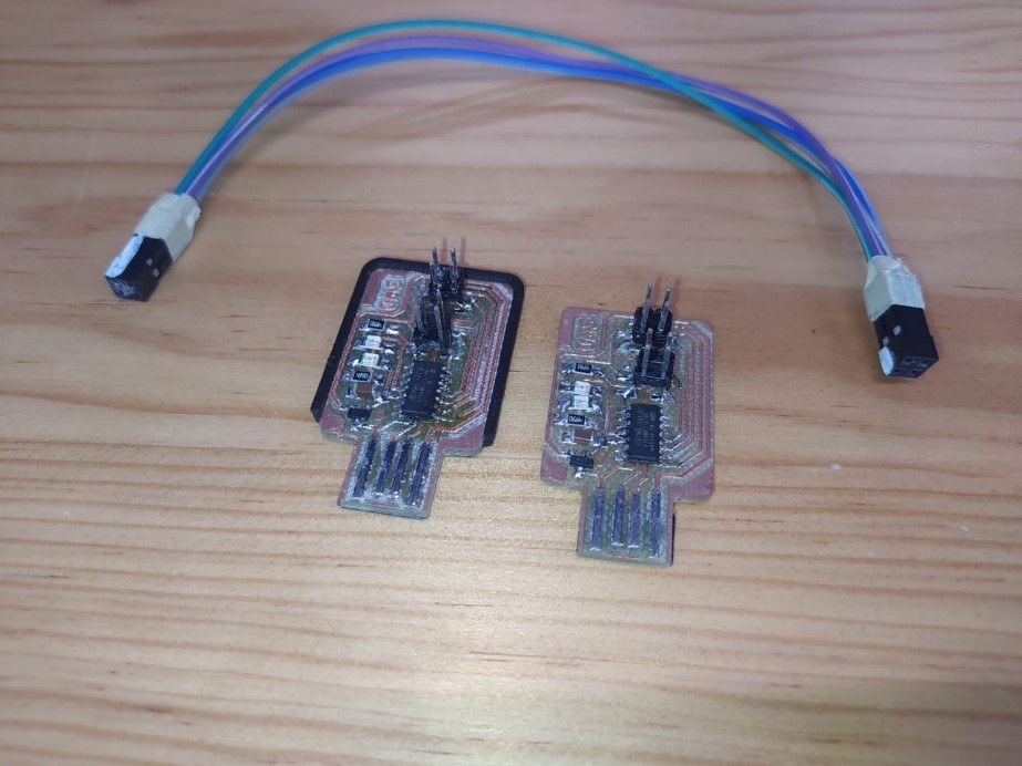
(12) It is the first time that I will weld surface mount components, so I am going to machine 2 boards, anticipating errors in the assembly of components
I already did some tests on the tracks of the group assignment so if it is also your first time here are some tips:
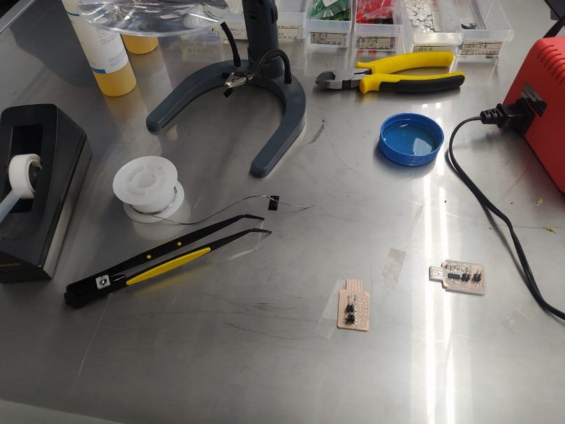
(13)
• Attach your plaque with a 3D printed base, commercial triple arm or even double-sided tape to an MDF base. This can be a great differentiator. (look for surfaces with materials that do not generate static)
• The liquid cleaner with FLUX is your best friend, don't be afraid of it, it considerably increases the adherence of the solder.
• A thin tip for your soldering iron or soldering station will greatly facilitate your work.
• Look for the ideal temperature recommended by the welding manufacturer. (in my case 350°)
The process that I followed was the following.
• Clean the board with isopropyl
• Apply Flux on the surface to be welded.
• Apply a small amount of solder to the contact area.
• With a pair of tweezers take the component and place it in its position.
• Make contact with the soldering iron and wait one or two seconds maximum.
• When you finish soldering all the components, clean the card with isopropyl alcohol spray.
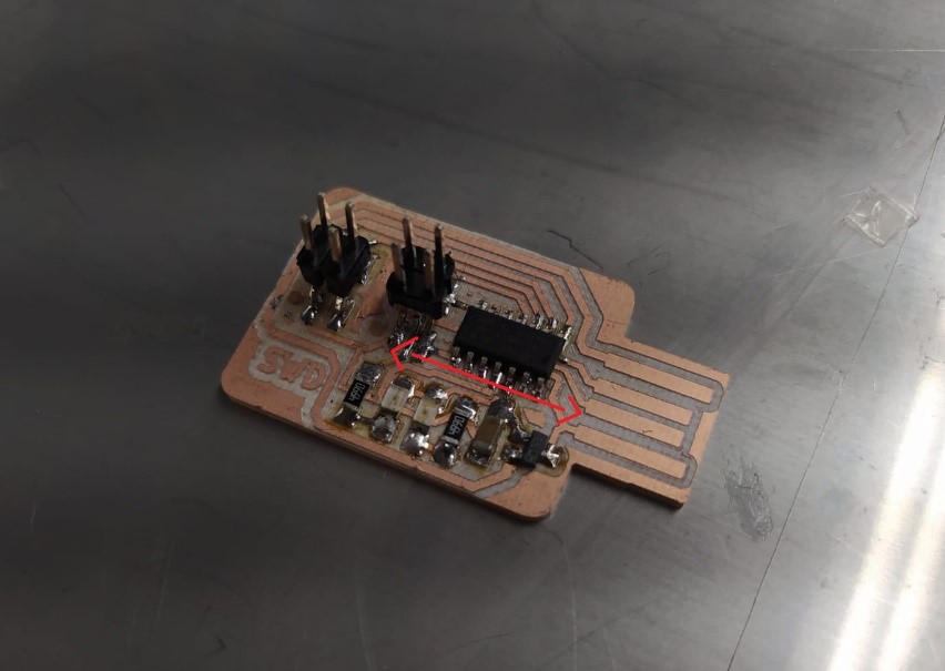
(14) The most difficult component for me was the microprocessor due to the size of its parts.
In case the terminals are joined with solder, there is a good trick: apply flux abundantly and pass the soldering iron in this direction. You can also apply Flux liberally and soak up the solder with desoldering cloth.
(15) Before starting with the programming of the programmer we need to verify:
• Continuity of the tracks according to the design
• The correct location and polarity of components
• Tracks joined by soldering, this can be solved by absorbing with desoldering mesh.
Now we need to load the bootloader so that our programmer can already program other boards, for this we must have the following resources.
1. EDBG latest version, you can download it from here.
https://taradov.com/bin/edbg/
Select the corresponding operating system and version.
2. Bootloader
You can download the latest version here.
https://gitlab.fabcloud.org/pub/programmers/programmer-swd-d11c
All of the above should be in the same folder.
(16)
3. In my case I used another SWD programmer to load the bootloader to my new programmer.
4. If, like me, you use another SWD programmer, you will only need a cable made with 4 female-to-female jumpers to communicate with both programmer.
(17)
We must recognize the output pins
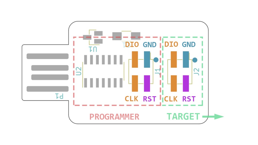
(18)
J2 is connected to the functional programmer and J1 is connected to the new programmer.
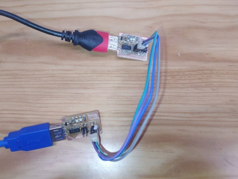
5. Finally we need two USB extension cables. Once the connections are made our programmers should look like this.
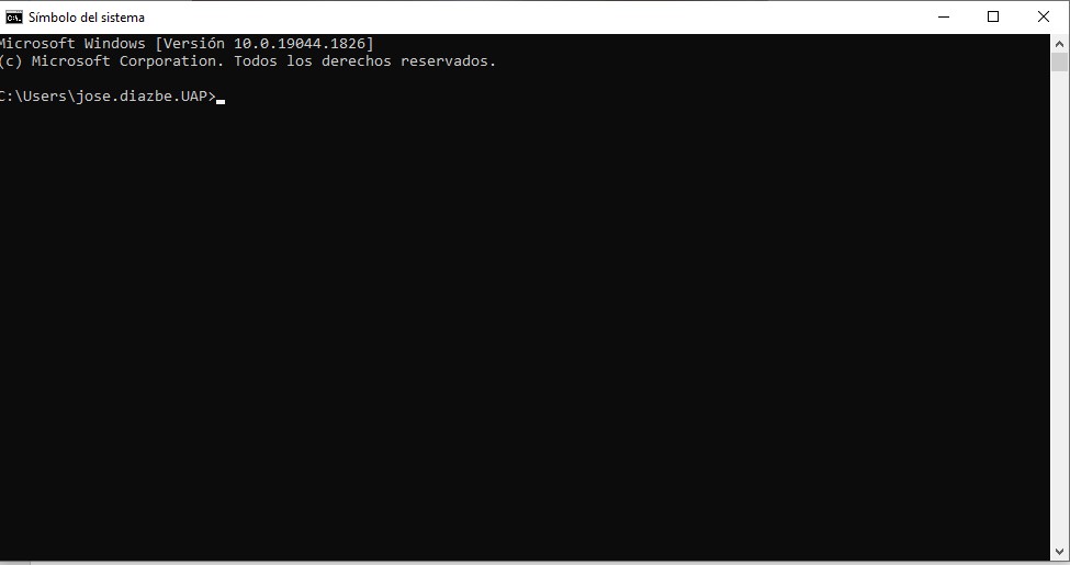
(19) Programming.
We run the command prompt.
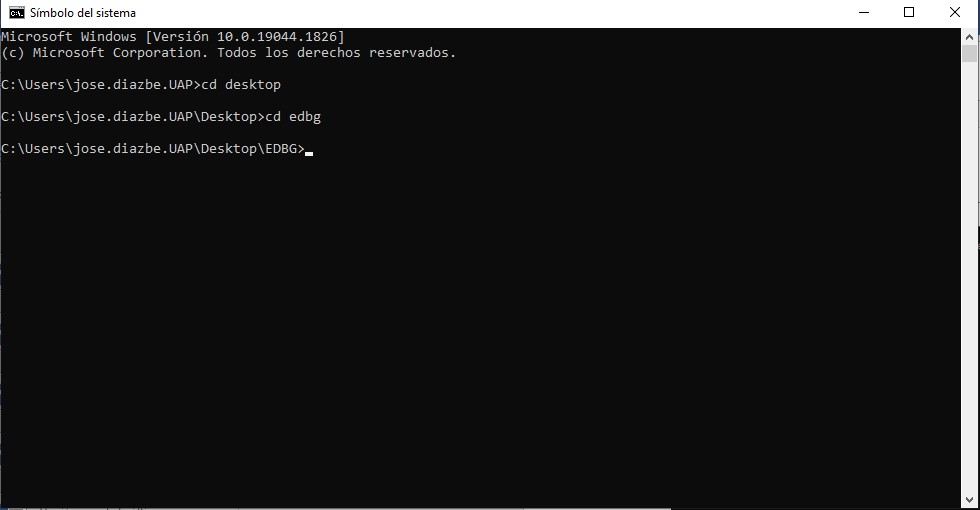
(20) We enter the location of our EDBG file and bootloader, in my case
Desktop > EDBG
(21) We execute the command
edbg-windows-r38.exe -ebpv -t samd11 -f free_dap_d11c_mini.bin
If you have a version other than 38 you must change the version number. R38, R39…
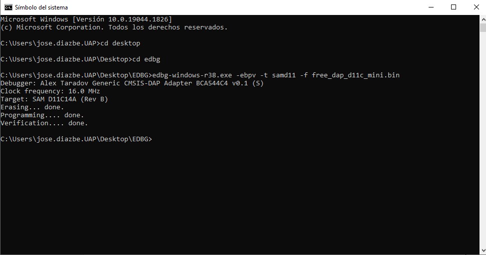
(22) If everything goes well you should see something similar to this, otherwise recheck the quality of assembly of the components or the connections.
Note. The functional programmer must be connected via USB to the PC and the new programmer must be connected to a different power supply, in my case a 5V eliminator.
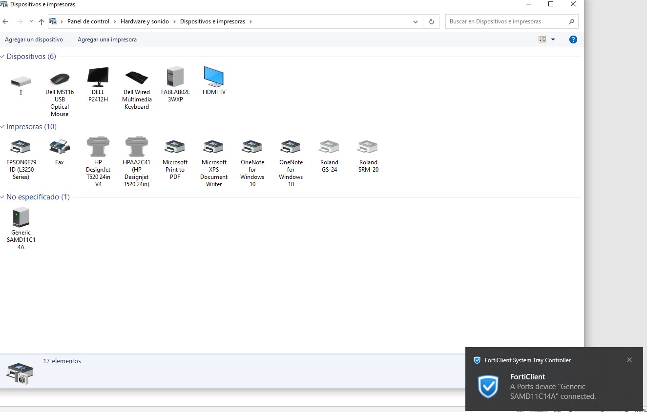
Now when connecting our new programmer the PC will recognize it as a functional device.
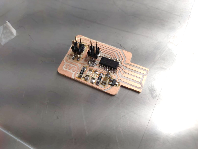
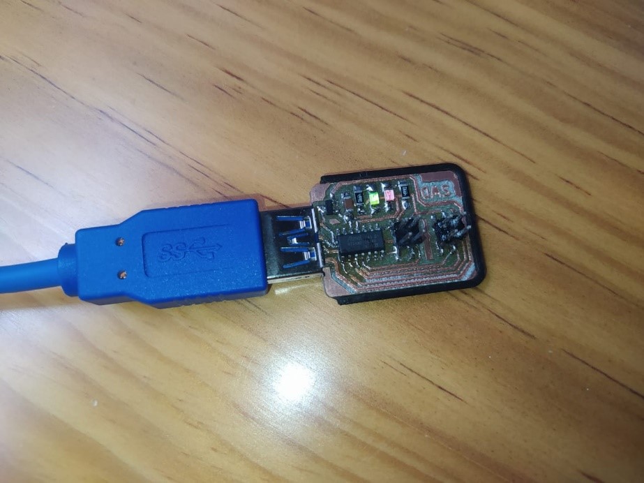
(23) This is what our ready programmer looks like.
Update 08/02/2022
(24) To test its functionality we are going to try to program another SAMD11. To do this we will download the corresponding binary. (in this case to be programmable with Arduino)
https://github.com/qbolsee/ArduinoCore-fab-sam/blob/master/bootloaders/zero/binaries/sam_ba_SAMD11C14A.bin
We make the corresponding connections and execute:
edbg-windows-r38.exe -ebpv -t samd11 -f sam_ba_SAMD11C14A.bin
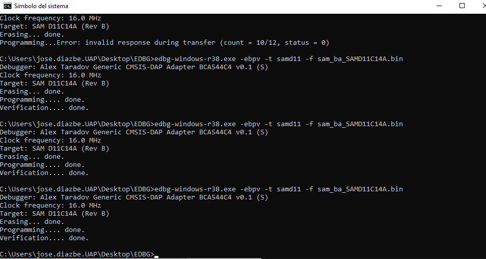
The first error was generated because the board to be programmed was not connected to power.
(25) Videos.
Copyright 2022 Jose Manuel Diaz Bello