Group Assignment – Electronics Production - Puebla
General objective (group assignment):
• Characterize the design rules for your in-house PCB production process: document feeds, speeds, plunge rate, depth of cut (traces and outline) and tooling.
• document your work (in a group or individually)
• Document your work to the group work page and reflect on your individual page what you learned
Model SRM-20
• Cuttable Material: Modelling Wax, Chemical Wood, Foam, Acrylic, Poly acetate, ABS, PC board
• X, Y, and Z Operation Strokes: 203.2 (X) x 152.4 (Y) x 60.5 (Z) mm
• Workpiece table size: 232.2 (X) x 156.6 (Y) mm
• Distance From Collet Tip to Table: Max, 130.75mm (5.15 in)
• Loadable Workpiece Weight: 2 kg (4.4 lb)
• X-, Y-, and Z-Axis Drive System: Stepping motor
• Operating Speed: 6 - 1800mm/min / 0.24 - 70.87inch/min
• Software Resolution: 0.01 mm/step (RML-1), 0.001mm/step (NC code) 0.000039 inches/step (RML-1), 0.000039 inches/step (NC code)
• Mechanical Resolution: 0.000998594 mm/step / 0.0000393 inches/step
• Spindle Motor: DC motor Type 380
• Spindle Rotation Speed: Adjustable 3000 - 7000 rpm
• Cutting Tool Chuck: Collet method
• Interface: USB
• Control Command Sets: RML-1, NC code
• Power Requirements Machine: DC24V, 2.5A / Dedicated AC adapter: AC 100-240 V ±10%, 50/60 Hz
• Power Consumption: Approx. 50 W
• Operating Noise: During operation: 65 dB (A) or less (when not cutting).
Development
Welcome to this week's group assignment. I hope that this documentation will be useful to those students who have an SRM-20 in their fablabs.
How to produce a PCB in a SRM-20?
The first thing we must consider is that this equipment is very good for PCB manufacturing processes, although we have to make some adjustments before starting.
Problem 1
The Z axis of the machine is a limitation in combination with the average height of 1/64" and 1/32" tools. There is a separation of approximately 25 mm which initially makes it impossible to manufacture the PCBs.
Problem 2
If the machine and the tools allow you to unwind enough to process the PCB boards, it is important that we place a sacrificial base, otherwise we can cause serious damage to the platform of our machine.
Solution 1
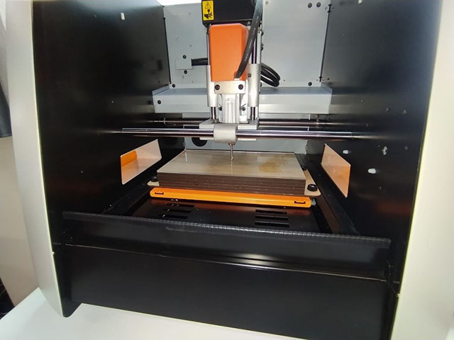
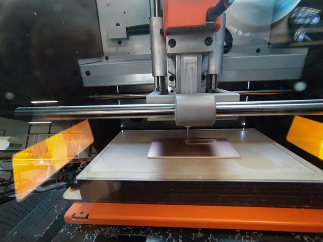
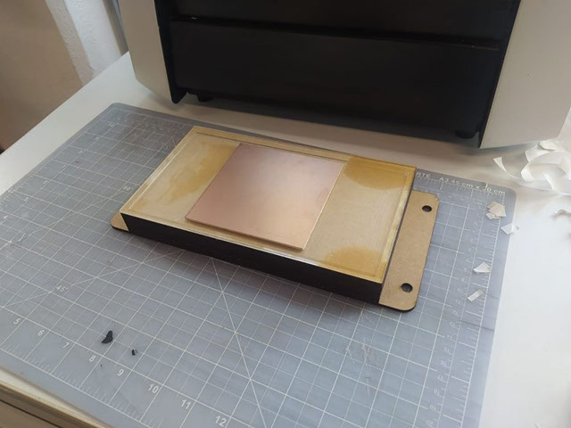
In order to solve these two problems, I designed a sacrificial base that also allows it to reach sufficient height, for this I used Acrylic and 3mm MDF, I made these pieces with laser cut, I used the machine screws to guarantee a perfect assembly.
After some tests the result was the following:
Problem 3.
The traces and cuts of the PCB boards require a millimeter precision with respect to the Z axis, as I added height by stacking layers of material, different heights derived from the layers of glue, quality of the materials and anchoring to the machine were generated.
These are some of the defects that we could cause if we place our plate without rectifying the surface of the sacrificial base.
• Different qualities in the cut or traces.
• Increased tool wear.
Solution 02
With a 1/8” flat tool we proceed to rectify the surface to guarantee the same height at any point of the base. I used a 1mm thick rectangle and generated the G code with MODELA Player 4
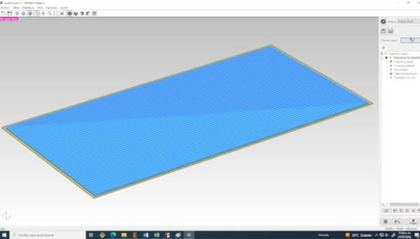
The result:
Now that we have the surface anchored and rectified, we can go to the phase of testing tools, speeds and file feeding:
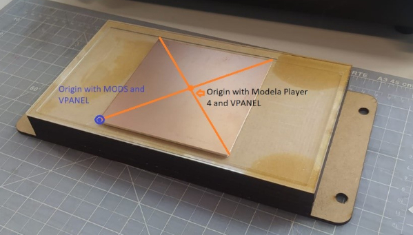
For this process we will use Mods and Vpanel to generate and send the files to the machine.
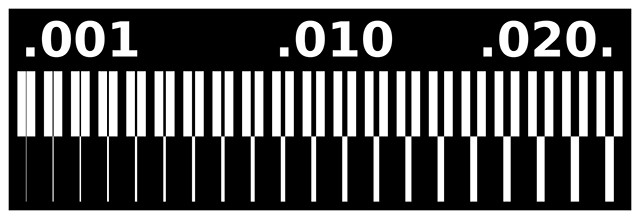
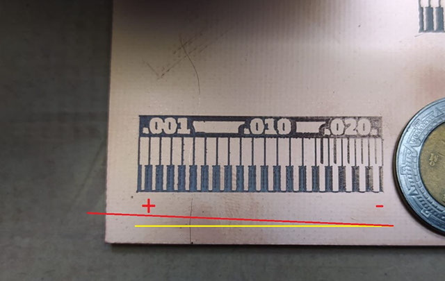
This is the template I used to characterize the speeds and tools, the files are available here:
academy.cba.mit.edu/classes/electronics_production/index.html
We enter mods
http://mods.cba.mit.edu/
We will start by right clicking and then:
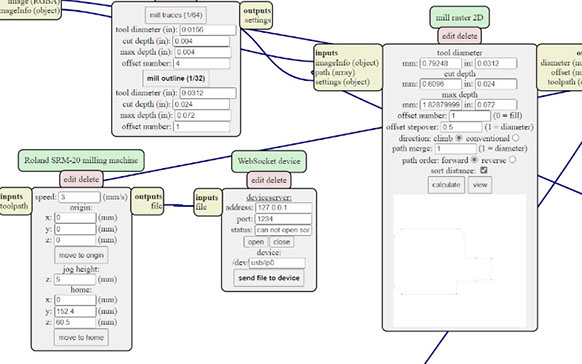
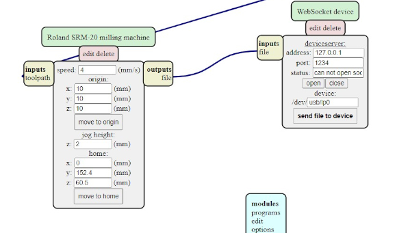
Programs > Open server program > SRM20 > PCB PNG
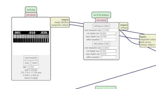
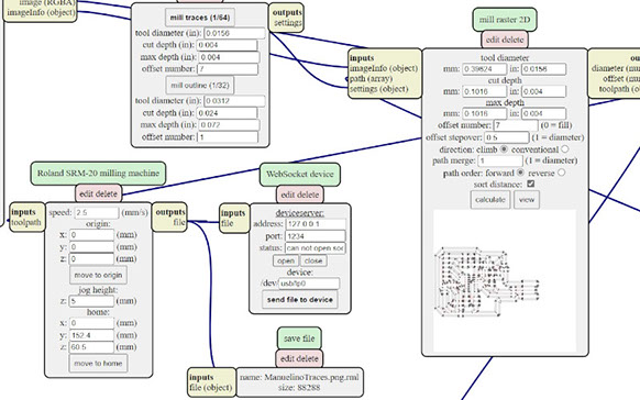
Select PNG File > Mill traces
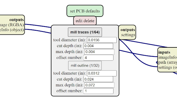
These values can be modified to experiment with different finishes and cutting times.
Calculate
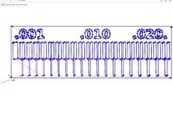
At this point I had another problem since I didn't know how to download the Gcode. After a bit of experimentation, I found the process to download the file:
"Note" the following steps are for users who are using Mods in browser and from Windows
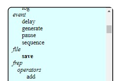
Right click >> Modules > Open server module > File > Save
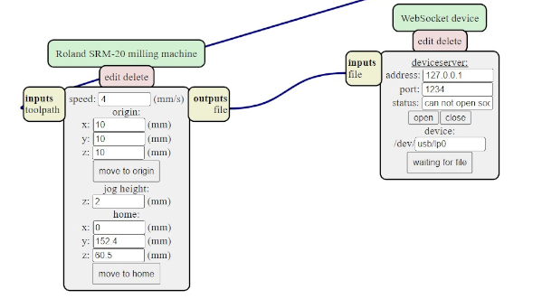
In the Roland SRM-20 milling machine we disconnect the output that goes to the Websocket device by clicking on the text at both ends.
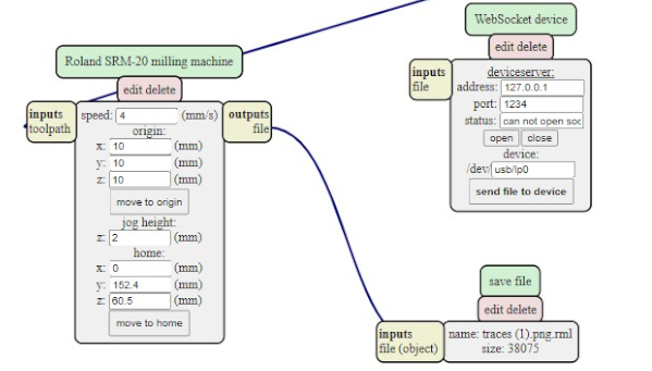
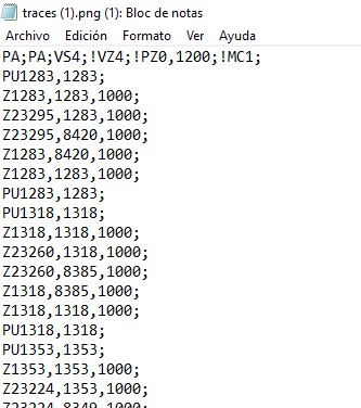
Then we connect the output to the “Save File” module as shown in the previous image. Finally, we click on "Calculate" again, automatically the browser will download the G code after recalculating
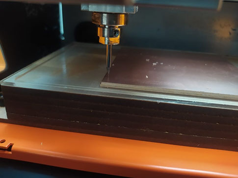
After obtaining the manufacturing codes, I mounted the board to our sacrificial super base, I used double-sided adhesive tape
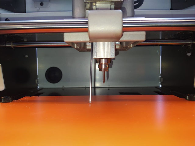
Then with the help of Vpanel, we move the machine head to a comfortable position to place the tool:
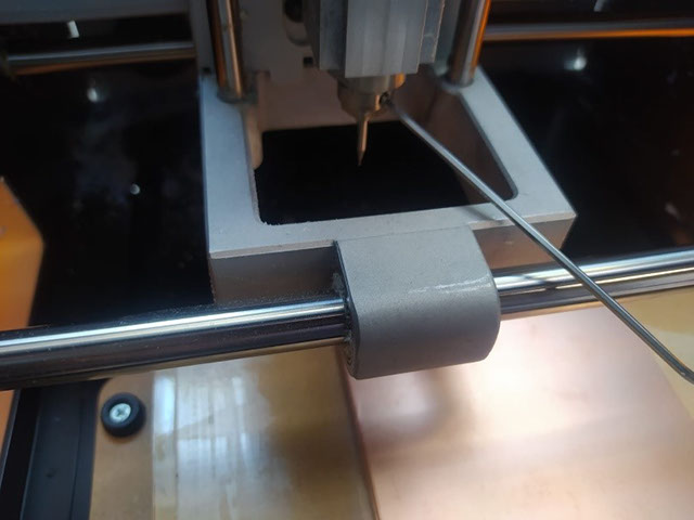
This information can save material and cutting tools:
Now we save the origin according to the position of our material, using these two buttons.
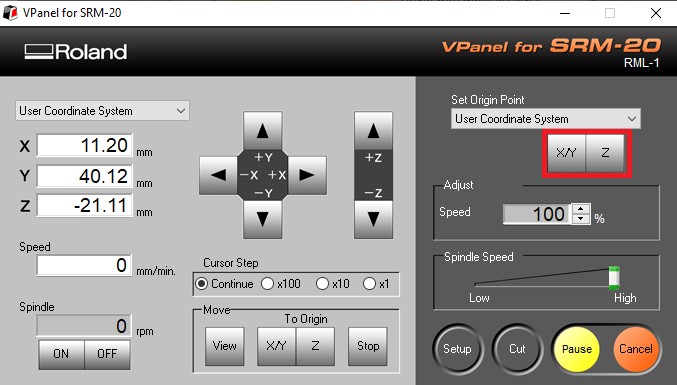
Z calibration is very important, maybe 50% of the success of our work depends on it. I recommend lowering the tool almost to contact with the plate and then loosening the tool so that it makes a more precise contact, finally we tighten the tool again. This step must be done very carefully to prevent the tool from falling on the plate. We can support it with our hand or with a tool.
The time has come! we send our g code from VPANEL for this we execute the following steps: Cut > Add > Select File> Output.
Before sending make sure to verify that everything is in order.
Below are some of the tests I did.
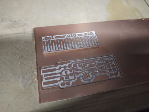
The time has come! we send our g code from VPANEL for this we execute the following steps: Cut > Add > Select File> Output.
Before sending make sure to verify that everything is in order.
Below are some of the tests I did.
Traces
Outline