Week8- Embedded Programming
Introduction
Half of the week under lockdown and half of the week I could access the lab. But even after all this lockdowns, I still canot get used to online learning. I prefer learning in the lab, the old traditional method. Moreover, I didnot in my wildest dream expect that I would be creating a website and have to do programming and yet here I am doing both (Life works in mysterious ways 😅 ). Personally for me, this week is the toughest. To be honest, even after the global lecture, I could only understand 5% of what Neil taught us. Even after rewatching the global lecture recorded video 2 times I still didnot get a clear picture. So, now its upto god (the truth- lots of googling and watching tutorials ).
Assignment
group project:
- compare the performance and development workflows for other architectures
individual project:
- read the data sheet for your microcontroller use your programmer to program your board to do something
- extra credit: try other programming languages and development environments
Group assignment
The group assignment is here
Atmel ATtiny 44
Datasheet
Are you still confused about this week's assignment?
Want to learn the datasheet but dont know where to start?
Dont worry, you are not the only one. I am in the same boat.
I highly recommend you to study Make:AVR programming by Elliot Williams.
-
An excerpt from the book states that:
"The trick is to approach the datasheet like a reference book rather than a novel. If you’re learning a new foreign language, you don’t start by opening up a dictionary to page one and reading onward. A dictionary is most useful when you already have a basic idea of how the language works, but you’ve just forgotten how to say “lemur” in Portuguese."
This book explains the terminologies in easy sentences and was really helpful to me.
Microcontroller
For the electronics design week, I made a hello world board using the ATTINY 44 microcontroller. The ATTINY 44 microcontroller which is not even the size of an almond, it's datasheet contains 299 pages !!!! Luckily, Neil informed us that we dont have to study or memorize all the pages but scroll and study the parts which we actually use (which makes total sense as well)
Features of ATTINY44:
- 8bit
- 14 pins
- RISC architecture
- 32 x 8 General Purpose Working Registers
- Memory: 4K Flash Program Memory, 256 B EPROM and 256 B SRAM
- Peripheral Features
- One 8-bit and One 16-bit Timer/Counter
- 10-bit ADC
- Programmable Watchdog Timer
- On-chip Analog Comparator
- Universal Serial Interface
- Special features- debugWIRE On-chip Debug System
- I/O and Packages: 12 Programmable I/O Lines
- Operating Voltage: 1.8 – 5.5V
Pin-configuration
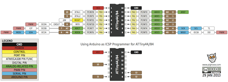
#NOTE - If you are using arduino IDE to program the board, for the pins use the numbers represented in the brown box while writing the program.
Pin description
- VCC- supply volatge
- GND- Ground
- Port (PA7:PA0)
- Port B (PB3:PB0)
- RESET- PB3
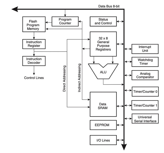
Architectural overview
The ATtiny44 microcontroller uses Harvard architecture
Arduino IDE
I used Arduino IDE to write the program which uses C+ language.
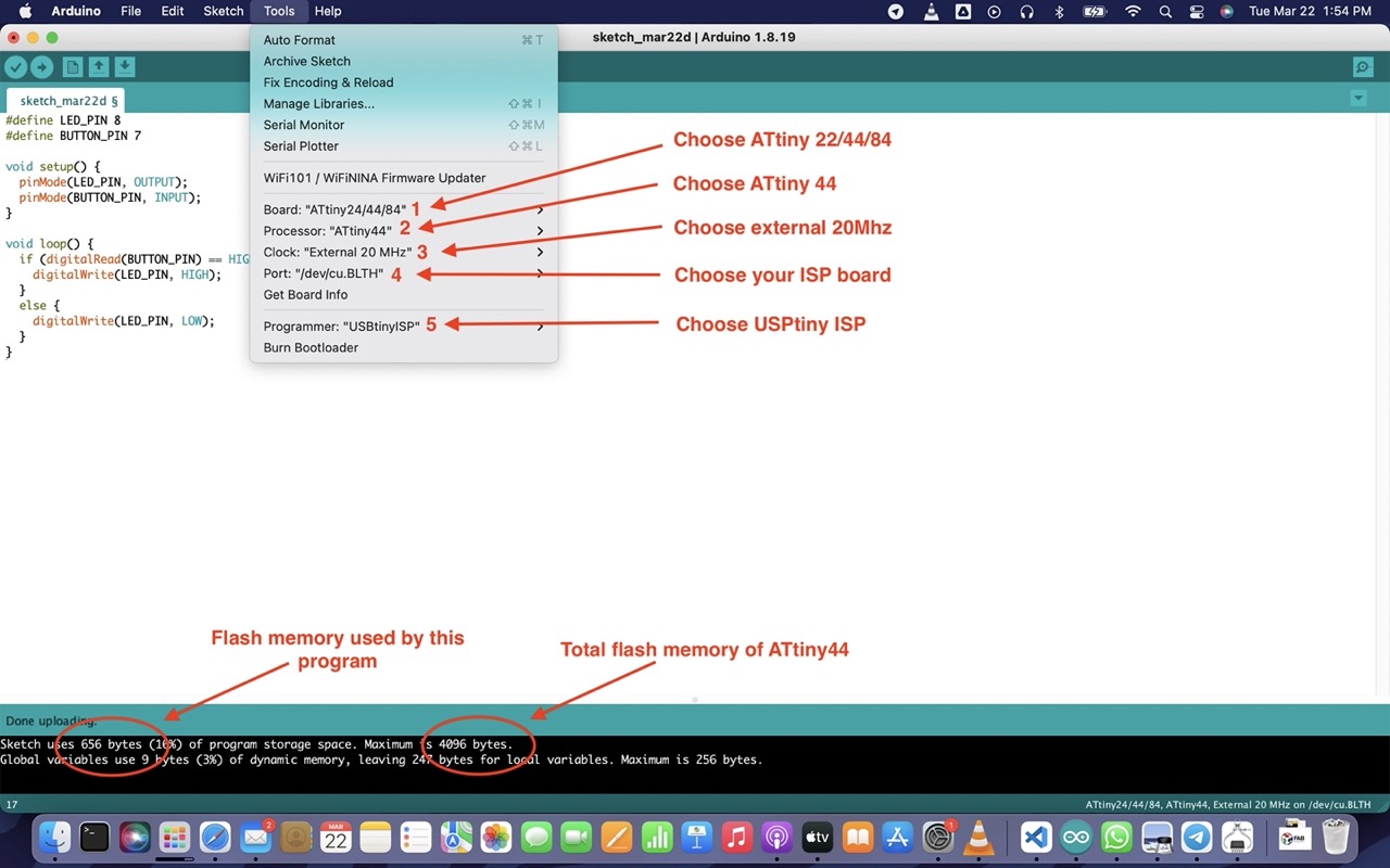
Settings
-
To program the ATtiny85 we need to first set Arduino Uno in ISP mode. Follow this instructions to configure Arduino Uno as a ISP
-
Setting up Arduino Environment
Programming
1. In tinkercad
Software: TinkerCAD
Since the country is under lockdown and I left my ISP board in the Fablab, I thought maybe I could program and do it online (simulation) in TinkerCAD to check if the program works or not till the government announces some relaxations.
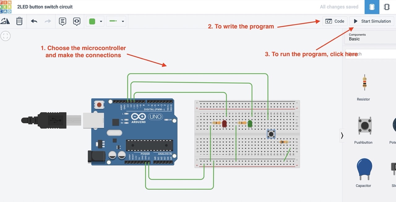
Program: LED1 blink at 0.5s delay and LED2 blink at .25s delay simultaneously
// Which pins are connected to which LED
const byte LED1 = 11;
const byte LED2 = 12;


// Assigning delays.
const unsigned long LED1_interval = 500;
const unsigned long LED2_interval = 250;


// Declaring the variables holding the timer values for each LED.
unsigned long LED1_timer;
unsigned long LED2_timer;


// Setting 3 digital pins as output pins and resetting timer
void setup ()
  {
  pinMode (LED1, OUTPUT);
  pinMode (LED2, OUTPUT);

  LED1_timer = millis ();
  LED2_timer = millis ();

  }  // end of setup


//LED1 loop that turns it ON if it is OFF and vice versa
void toggle_LED1 ()
  {
   if (digitalRead (LED1) == LOW)
      digitalWrite (LED1, HIGH);
   else
      digitalWrite (LED1, LOW);


  // remember when we toggled it
  LED1_timer = millis ();
  }  // end of toggleLED_1


//LED2 loop
void toggle_LED2 ()
  {
   if (digitalRead (LED2) == LOW)
      digitalWrite (LED2, HIGH);
   else
      digitalWrite (LED2, LOW);


  // remember when we toggled it
  LED2_timer = millis ();
  }  // end of toggle_LED2

void loop ()
  {


  // Handling the blink of LED1.
  if ( (millis () - LED1_timer) >= LED1_interval)
     toggle_LED1 ();


  // Handling the blink of LED2.
  if ( (millis () - LED2_timer) >= LED2_interval)
    toggle_LED2 ();


/* Other code that needs to execute goes here.
   It will be called many thousand times per second because the above code
   does not wait for the LED blink interval to finish. */


}  // end of loop
2. With Hello-world board and ISP
Software: Arduino IDE
LED glows only when button switch is pressed
I already have the hello-world board and the ISP which I made during the previous weekly assignments. During the electronic week, I only tried blinking the green LED but this week I want to make the LED glow when button switch is pressed, but then when i tried, it wouldnot glow at all
Previously I was so hesitant when I found errors on my board because I thought that meant I was not doing a right job. But attending FabAcademy till date and by watching the recitation on debugging, my views on making mistakes changed completely. Now, whenever I find some errors, I am excited about debugging and learning how to troubleshoot. And for that, I would like to thank Fran (He is my instructor during FabZaero) for always showing me the positive side of making mistakes and learning from it. Now, mistakes are like beautiful scars to me.
Debugging
- First, I did the continuity test but everything was working
- Next, I tried the program in the tinkerCAD but the program was also working
- The green LED works fine when I tried with the blinking program
- But the program where the LED glows when button switch is pressed would not work, so when I looked at the connections, I noticed that there was mistake in the button switch connections.
My mistakes!
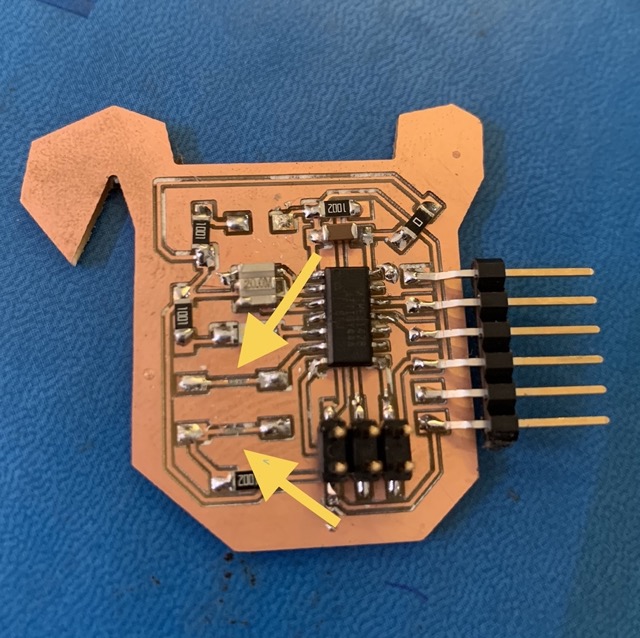
To rectify, I cut the connections between the switch with a blade and gave VCC supply to the switch button using an external wire.
After troubleshooting
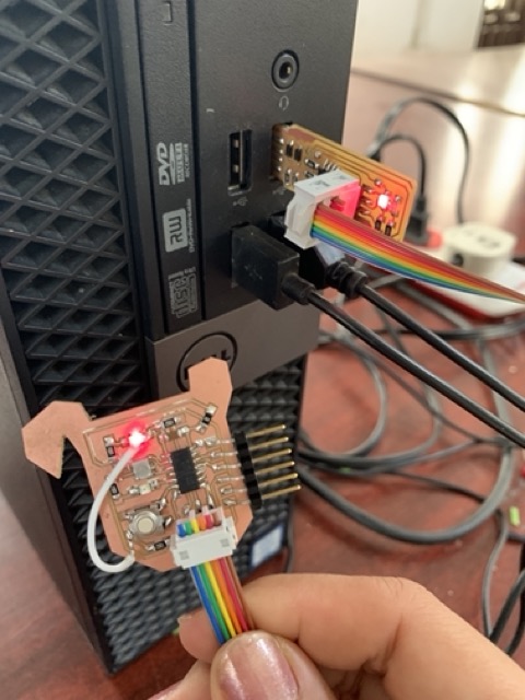
For the program, I used the blink program from the examples.
#define LED_PIN 8
#define BUTTON_PIN 7

void setup() {
  pinMode(LED_PIN, OUTPUT);
  pinMode(BUTTON_PIN, INPUT);
}

void loop() {
  if (digitalRead(BUTTON_PIN) == HIGH) {
    digitalWrite(LED_PIN, HIGH);
  }
  else {
    digitalWrite(LED_PIN, LOW);
  }
}
ESP 32 WROOM32
Software: Arduino IDE
For my final project ( motion sensor lamp ) I am using esp32 wroom32 microcontroller
For this week, I just tried using the PIR sensor as input and LED as output
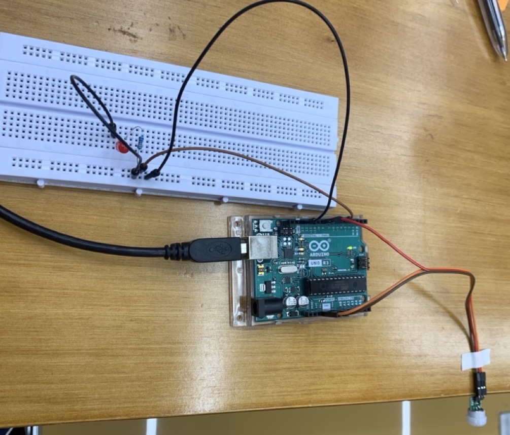
LED glows when motion when PIR sensor detects motion
#define PirInputPin 14 //signal for PIR sensor
#define Photoresistor //photoresistor
#define LedPin 12

int var;
void setup() {
 Serial.begin(9600);
 pinMode(PirInputPin,INPUT);
 pinMode(LedPin,OUTPUT);// put your setup code here, to run once:

}

void loop() {
 var = digitalRead(PirInputPin);
 if (var == 1){
  digitalWrite(LedPin,HIGH);
  Serial.println("Led is ON");
 }

 if(var == 0){
  digitalWrite(LedPin,LOW);
  Serial.println("Led is OFF");
 }
 Serial.println(var);
 //delay(2000);// put your main code here, to run repeatedly:

}