Week13- Networking and Communications
Introduction
Sometimes we don't know where to start and gets stuck. This week is like that for me. But then I got a trick, I recommend you all to check the pages of previous years student's pages. Some students really write good notes and links the references they used. I personally prefer referring Francisco, Quentin, Zina, Adrian and many others. After referring their pages, I know where to start and then I youtube a lot of tutorials on the week's topic.
Assignment
individual assignment:
- design, build, and connect wired or wireless node(s) with network or bus addresses
group assignment:
- send a message between two projects
Group assignment
The group assignment is here
Lecture notes
Inter-integrated circuit, I2C
-
I referred some tutorials on youtube to understand this topic better, Basics on I2C and How to use I2C with arduino
-
I2C is also called as TWI(two wired interface)
-
Protocol for sending and receiving data between integrated circuits
-
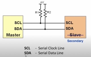
has only 2 pins/lines- SCL (serial clock line) and SDA(serial data line) who has 2 pull-up resistors pulled up to certain voltage, one for each line
-
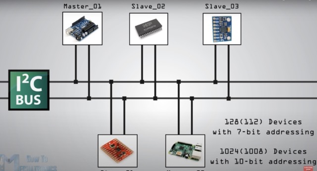
Can have multiple master and secondaries with just 2 wires.
-
Each master and secondary should have their unique addresses since they share the same bus.
Communication
-
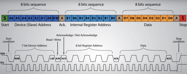
The data signal is transferred in sequences of 8-bit
-
After start condition,
-
the 1st 8-bit sequence is the address of the secondary to which data is being sent.
-
After each 8-bit sequence follows a sequence called A (Acknowledge).
-
After A, another addressing sequence follows which is the internal register address of the secondary device, followed by A.
-
Then it is data sequence, followed by A
-
Ends with special stop condition. SDA line goes from low to high while the SCL line is high.
-
A is used by the secondary device. When A is low (0), it means that the secondary device has successfully received the previous 8bit sequence.
-
From the 8-bit, the 7 bits are the arranged from most significant bit to least significant bit.
-
The 8th bit is R/W. R means read from the secondary device or W means write to the secondary device from the master device. Read is 1 and write is 0.
Individual assignment
For this week's assignment, we have to connect wired or wireless node(s) with network or bus addresses.
Wireless connection:
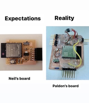
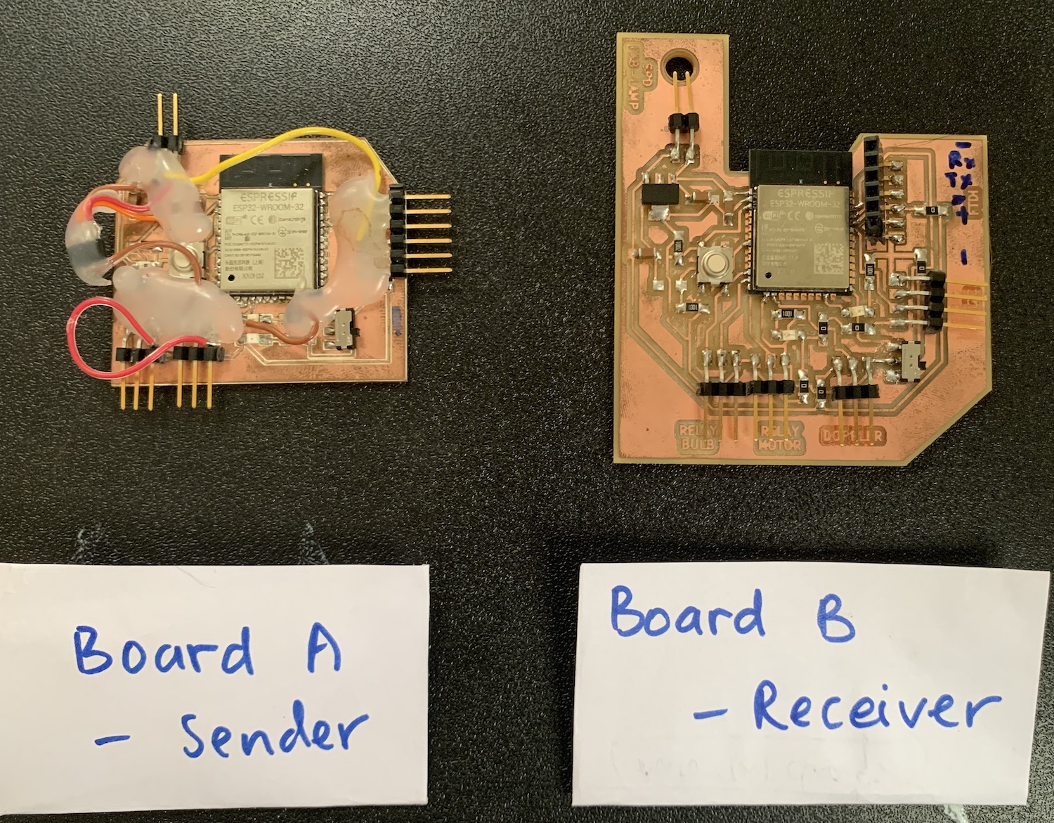
I am using esp32 module for the final project and so this week I wanted to explore more about ESP32 microcontrollers and how to communicate. I have started with my final project board and rectified as I went along, thats why I have 2 esp32 boards which I will be using here to communicate with one another.
Prerequisites
-
ESP32 add-on Arduino IDE. Instructions are here
-
Parts required. Make sure you have 2 esp32 boards ready. I milled my board during the output week
1. Getting mac address
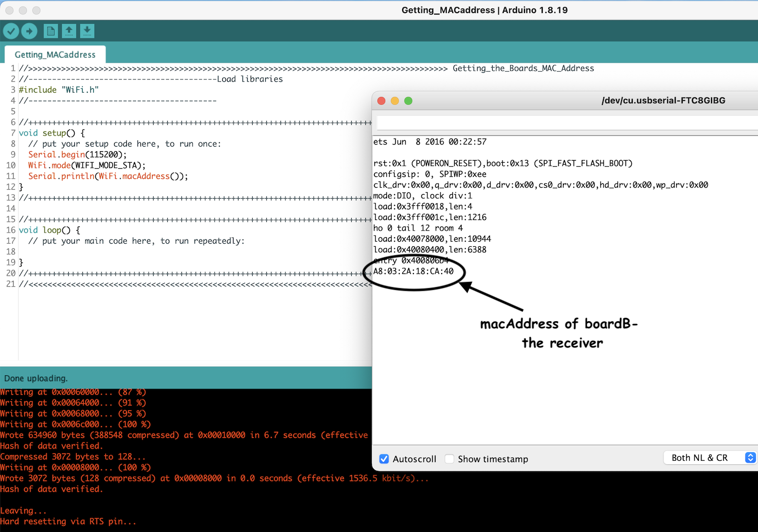
- Inorder to communicate with one another or to send messages between each board, we need to know their MAC address. MAC Address stands for Media Access Control Address and it is a hardware unique identifier that identifies each device on a network. MAC Addresses are made up of six groups of two hexadecimal digits, separated by colons, for example: 30:AE:A4:07:0D:64.
- Each board has a unique MAC address and we can even change the ESP32 MAC Address
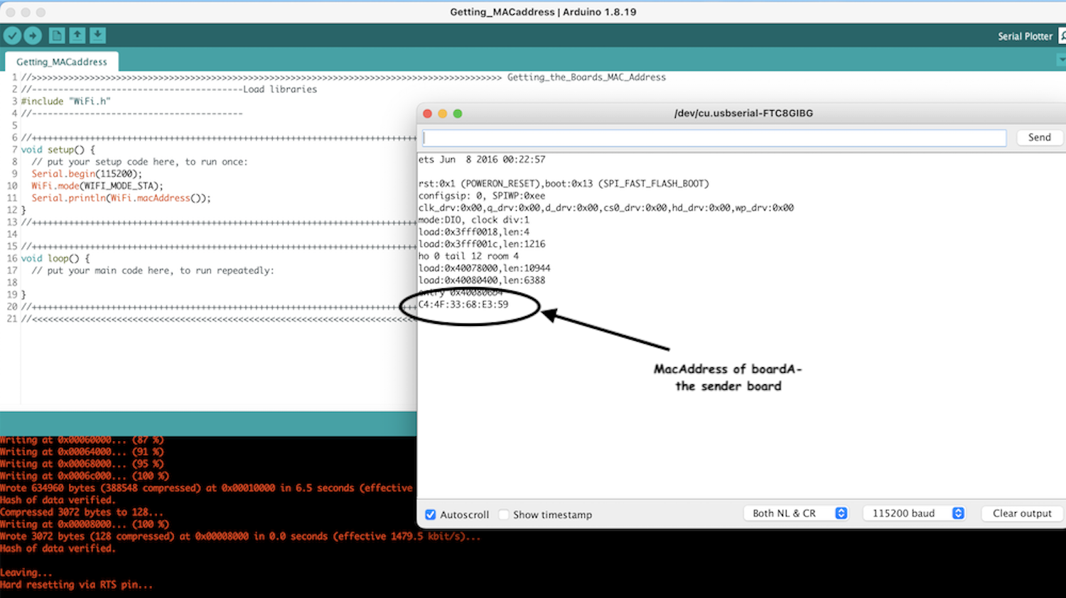
ESP32 board A- sender board
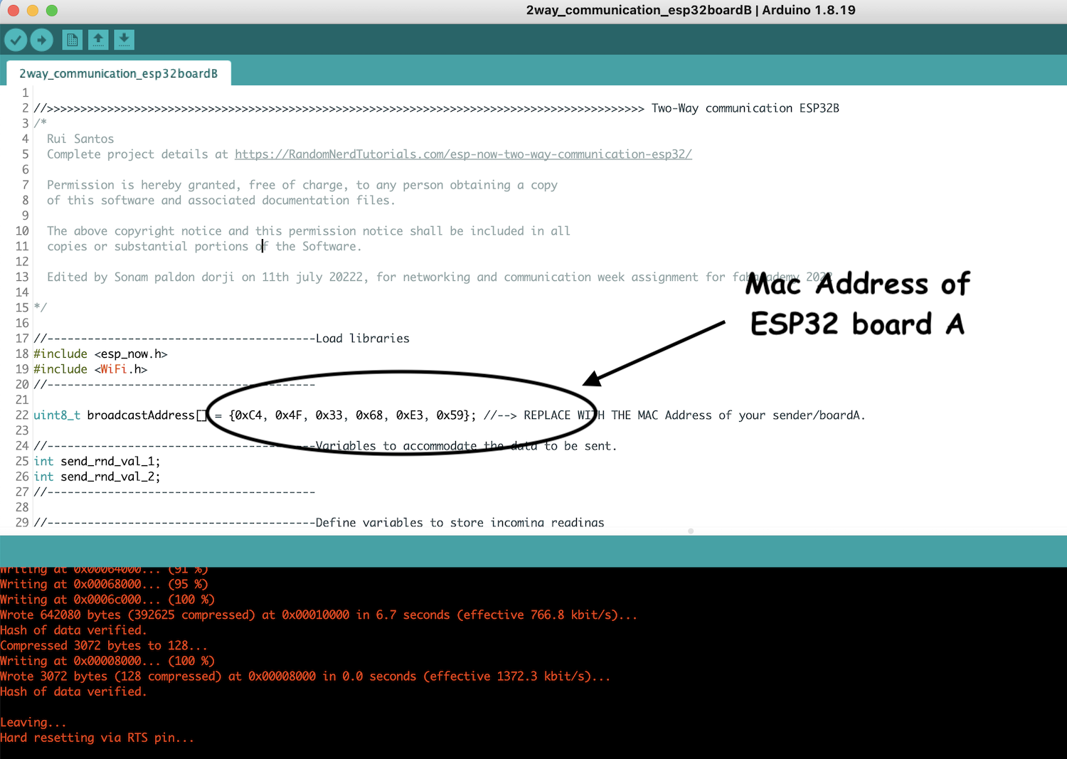
- MAC address= C4:4F:33:68:E3:59
- {0xC4, 0x4F, 0x33, 0x68, 0xE3, 0x59}

ESP32 board B- Receiver board
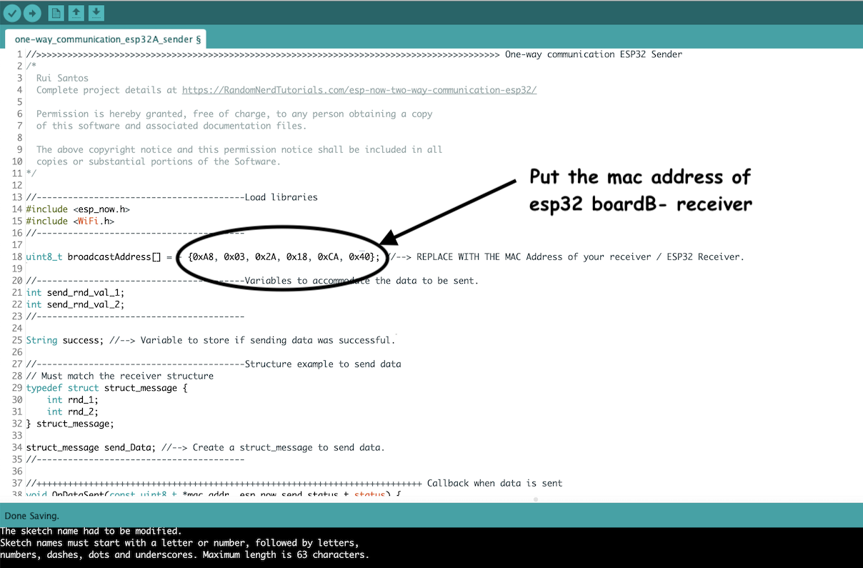
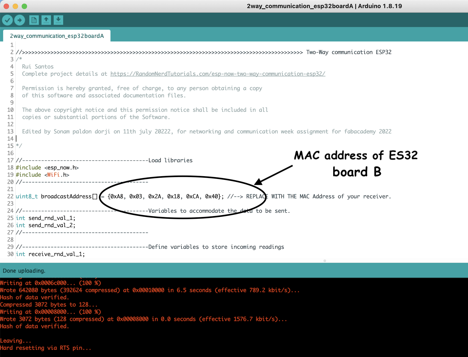
- MAC address= A8:03:2A:18:CA:40
- {0xA8, 0x03, 0x2A, 0x18, 0xCA, 0x40}
2. One-way communication
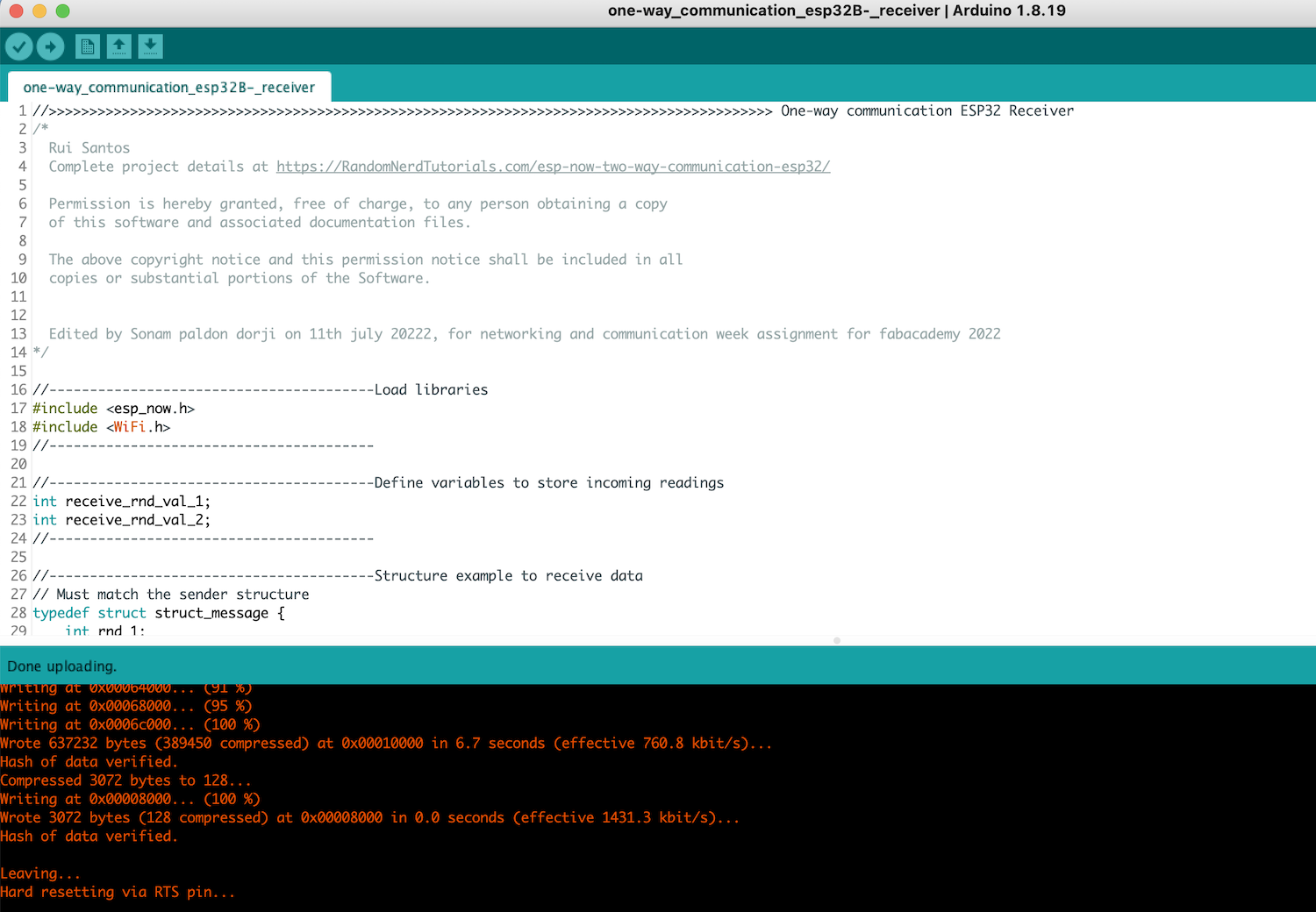
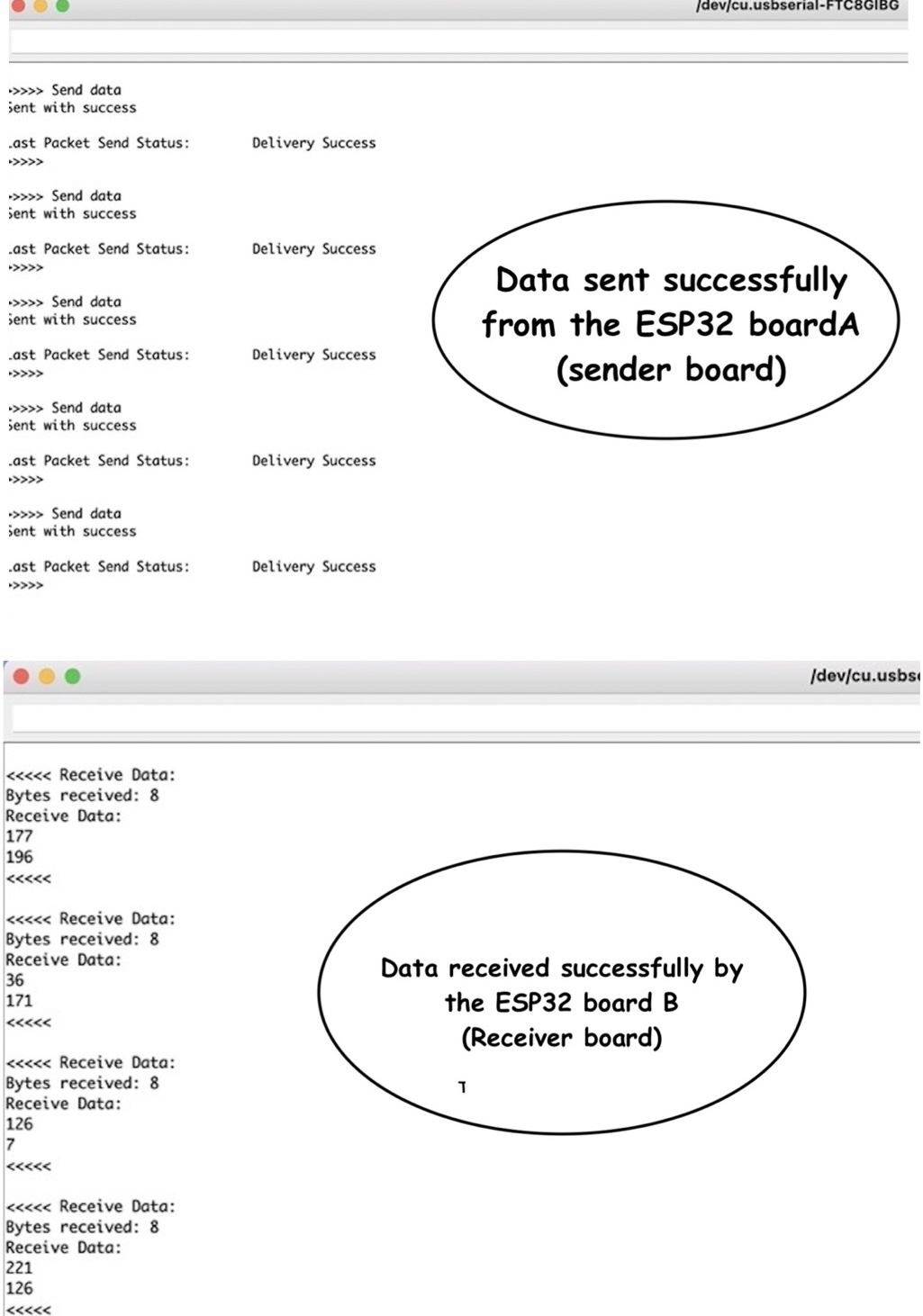
- The sender(BoardA) will send 2 random values to the receiver (BoardB)
-
Program the ESP32 board A(sender) first, putting the mac address of ESP32 board B(receiver) in the program to which the values will be sent
-
Program the ESP32 board B(receiver) then to receive the values.
-
Switch to run-mode in board the ESP32 boards to run the program.
3. Two-way communication
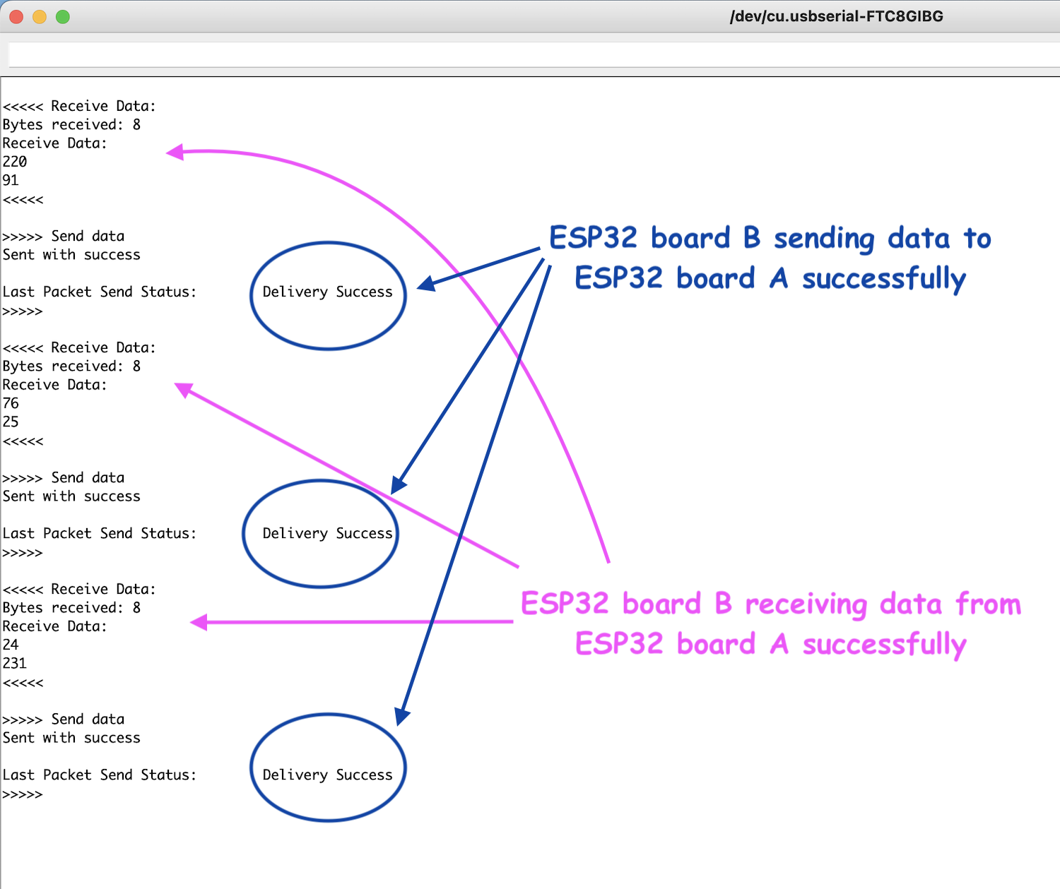
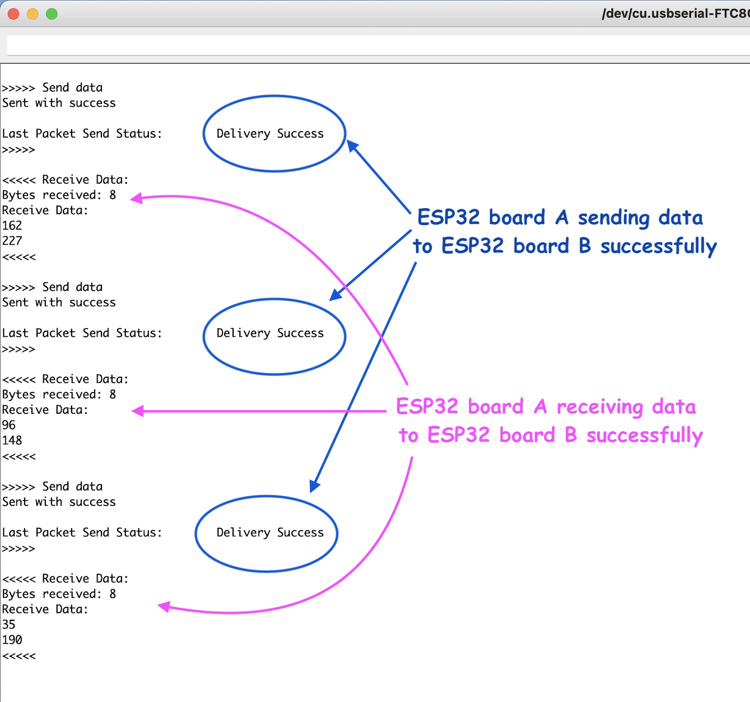
- The esp32 board A and B will send and receive 2 random values where by both the board A and B can send and receive the data
-
Program the ESP32 board A- putting the mac address of ESP32 board B to which data is being sent.
-
Program the ESP32 board B- putting the mac address of ESP32 board A to which data is being sent as it is a 2way communication now
-
Switch to run-mode and press the reset button on both the ESP32 boards to run the program.
-
Readings from serial monitor of ESP32 board A
-
Readings from serial monitor of ESP32 board B
