Week10- Output week
Introduction
Along with setting up a new fablab in one of the college in Bhutan with Fran and Sibu, I completed this week's assignment away from home in CNR fablab in Punakha.
Assignment
group project:
- add an output device to a microcontroller board you've designed, and program it to do something
individual assignment:
- measure the power consumption of an output device
Group assignment
The group assignment is here
Designing a board
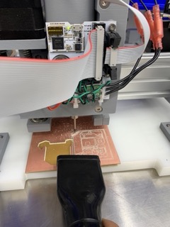
Machine used: Jake's clank LLZ machine.
Softwares: KiCAD, Arduino IDE, mods CE,
First of infinite attempts
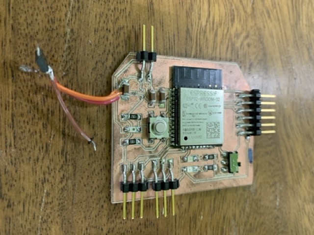
I used Jake's clank LLZ machine to mill the final project board. As much as I wanted my first designed, milled and soldered board to work in the first attempt, I failed miserably. I made the silliest mistake.
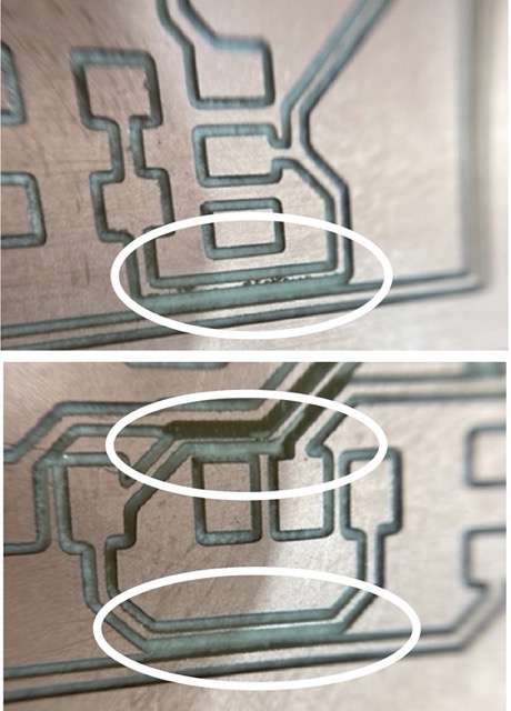
After milling:
After milling I noticed that the horizontal traces are very thin but when I checked the continuity, the connection was fine.
My beautiful mistakes and debugging those:
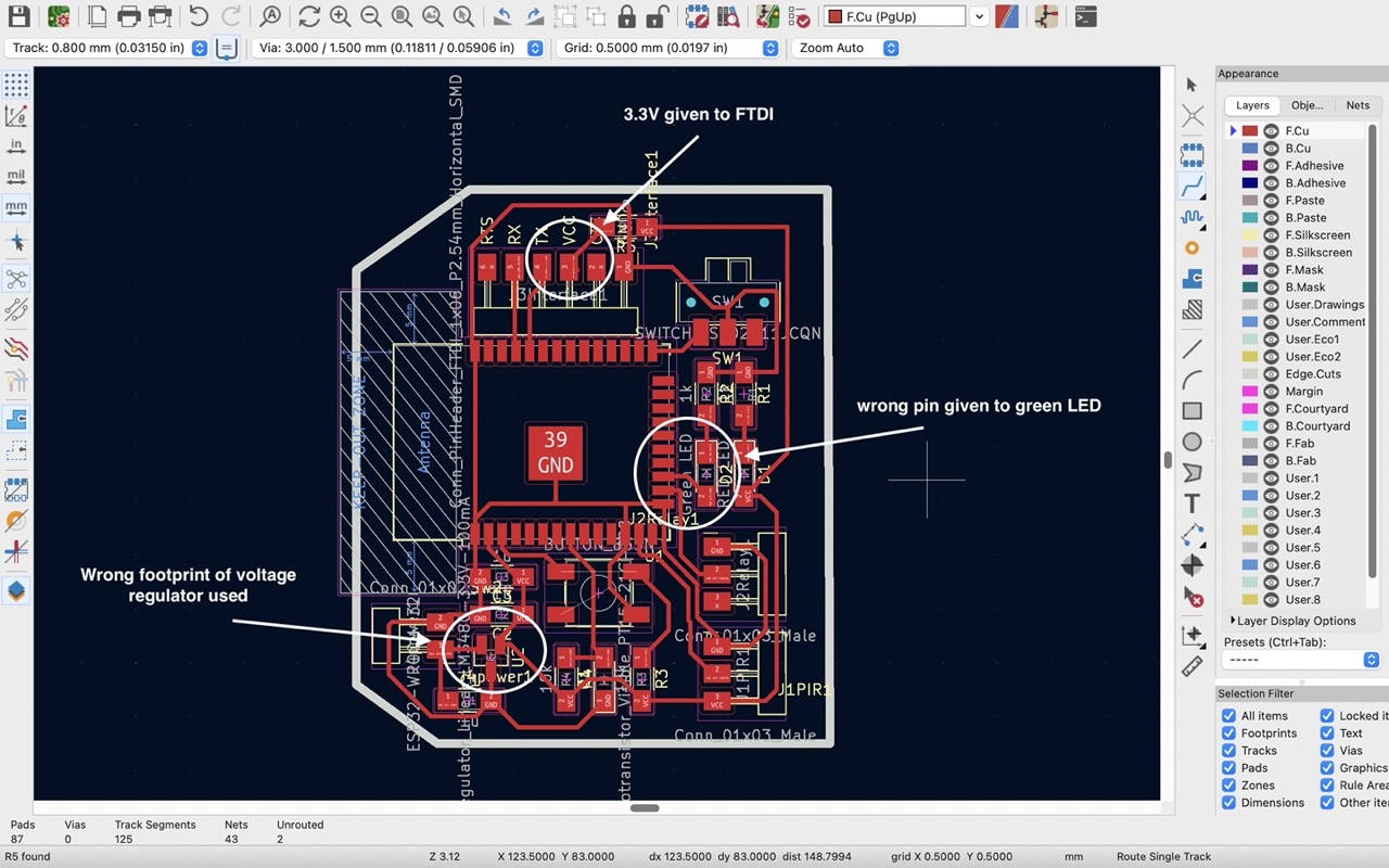
- I used wrong footprint for the voltage regulator in the design. So, I used jumper wire to connect the voltage regulator to the board.
-
In my design, I connected 3.3V to 5V of FTDI connector and as a result, the board short circuited. To rectify, I connected a jumper wire from the 5V pin of FTDI connector to the 5V pin of j4power1 connector.
-
The green LED glows as soon as the power supply is given to the board which should not be happening since I did not program the board yet. I found out the problem to be that the green LED was connected to a pin which cannot be used for input output pin, so I connected the green LED to another pin using a jumper wire.
Both of the problems are shown below:
Result:
- The board finally worked.
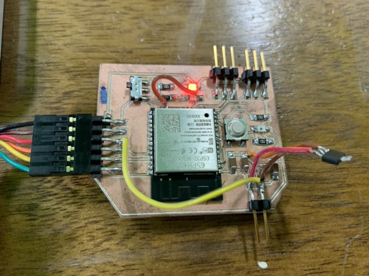
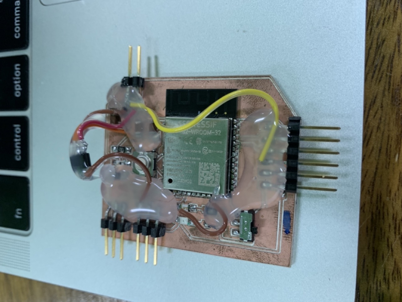
While I was putting the relay in and out, I broke the 1X3 male header. So I went to pick the only solution, HOT GLUE
Final corrected PCB design:
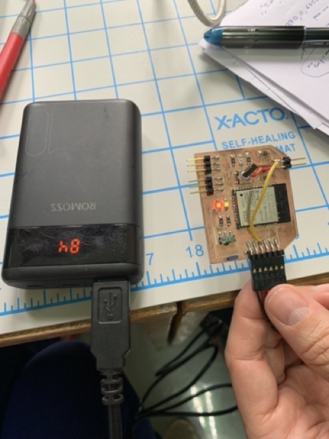
Note: Safety precaution
- Always use multimeter to check the continuity before giving supply.
- First supply the power from the power bank to check if the board works properly. Otherwise it will damage to USB port of the laptop.
- Then, you can connect to the laptop using USB or any source to program and run.
I will be using the rectified board and mill the final corrected board at the end for the final project presentation.
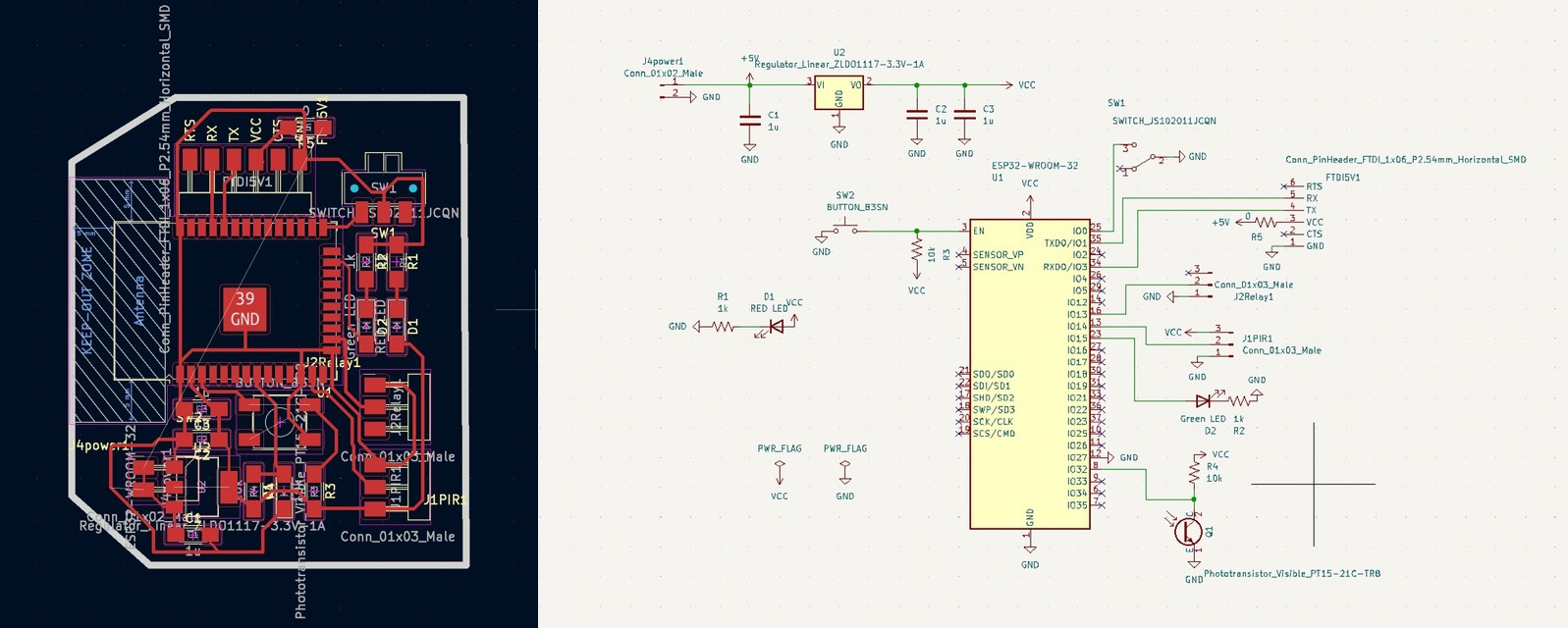
The edge and the traces of the board
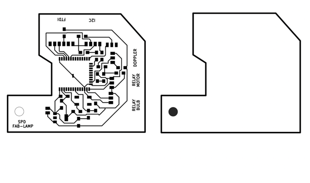
KiCAD Files of the board- output week KiCAD design esp32wroom32 bpard
Outputs
1. LED bulb
- I have already designed, milled and soldered a board for the final project. So, this week I got the opportunity to check if my output components work or not.
- For the final project, I am going to light a LED bulb, so I tried this week to control the LED using a relay.
- First, I tried to blink the internal green LED
- Secondly, I tried blinking the LED bulb.
2. Servo-motor
- Next, I connected servo motor as the output.
- Install the ESP32_Arduino_Servo_Library in the Arduino IDE following the instructions here
Programing
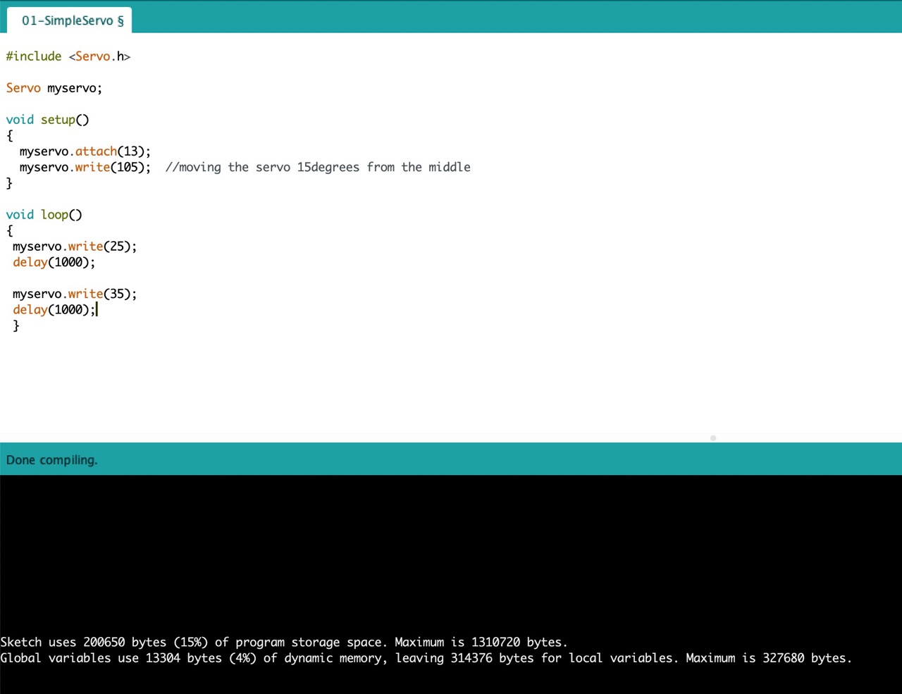
Servo Program file- Program in arduino