Task to be carried out this weekGroup Assignment
Action Plan
| Date | Work Allocation |
| 16th March | Lecture on Network and Communication by Prof. Neil |
| 23rd March | lecture on week's assignment by the local instructor(Suhas) |
| 24th March | Learning about communication protocols |
| 25th March | Board Design and Milling |
| 26th March | Soldering |
| 27th March | testing communication between the two boards |
| 28th March | Documentation |
Communication Protocols
Communication protocols are the rules that governs the communication between two electronic devices.Communications protocols can cover authentication, error detection and correction, and signaling. They can also describe the syntax, semantics, and synchronization of analog and digital communications.
Types of Communication Protocol
The communication protocol is broadly divided into two categories namely;
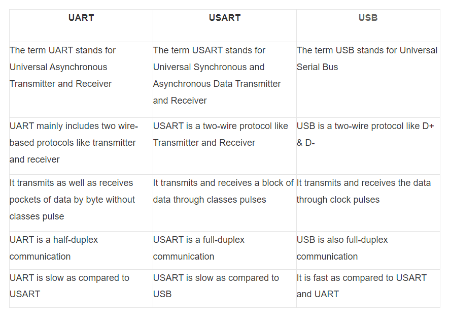
Inter System Protocol
These protocols are used for communication between two different devices. They are further divided into 3 major categories as follows;
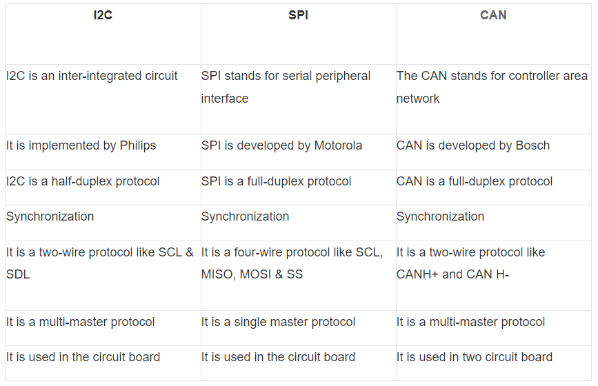
Intra System Protocols
The Intra system protocol is used to communicate the two devices within the same circuit board. The use of intra system protocol increases circuit complexity and power consumption but has higher security when transferring data.
The intrasystem portocol is divided into 3 major categories namely;
Reference: https://www.elprocus.com/communication-protocols/
Communication between two boards
For this week's individual assignment I had design, build, and connect wired or wireless node(s) with network or bus addresses. I opted to connect the two boards I designed during my Input and Output week to communicate.
For my Input week, I designed a board with LM35 Temperature sensor and for my output week, I used I2C LCD display as my output. This week, my plan is to get the readings of the LM 35 on my input board and get it displayed on the LCD connected to my output board.
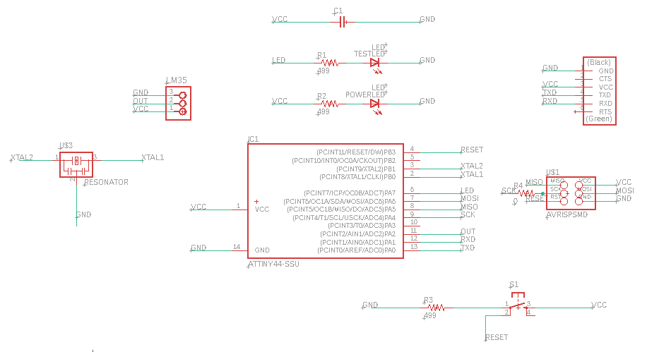
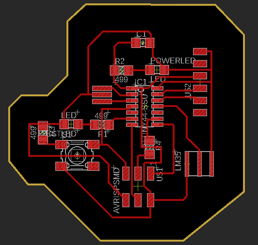
Schematic and Board Design
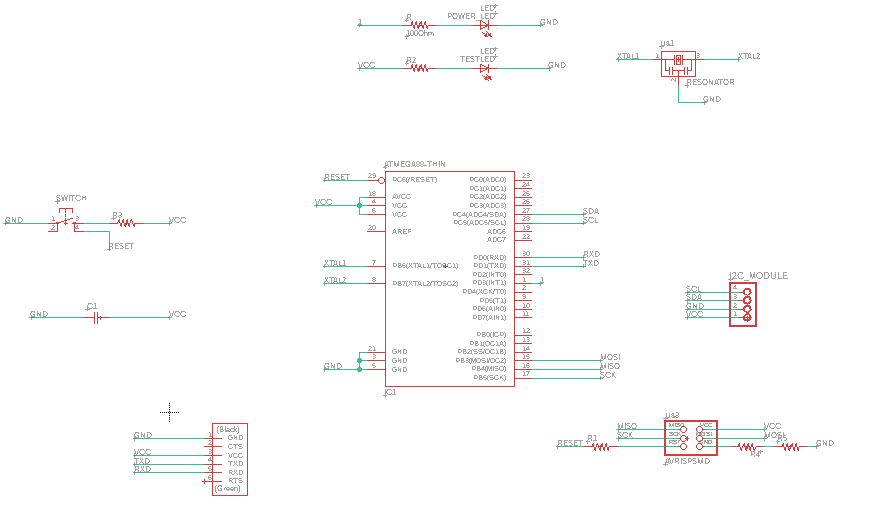
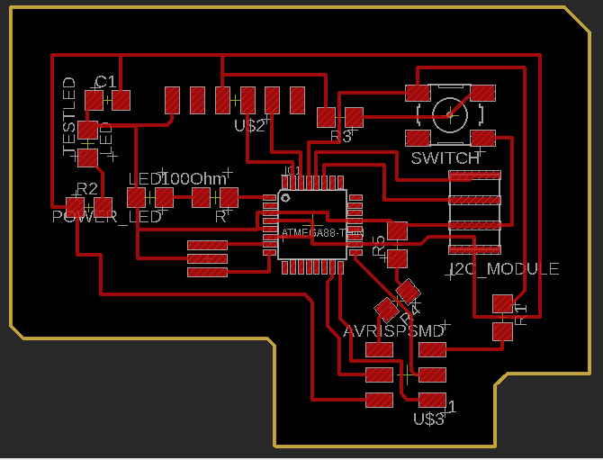
Since I used the boards that I made during my input and output week for this week's assignment, I didn't design any new boards. Shown below is the schematic and board diagram of my input board which has LM35 temperature sensor connection. The details of the board design can be found on my
input week assignment page
Similarly, the schematic and board diagram of my output week with I2C LCD connection can be seen below. The details of the board design can be found on my output week assignment page.
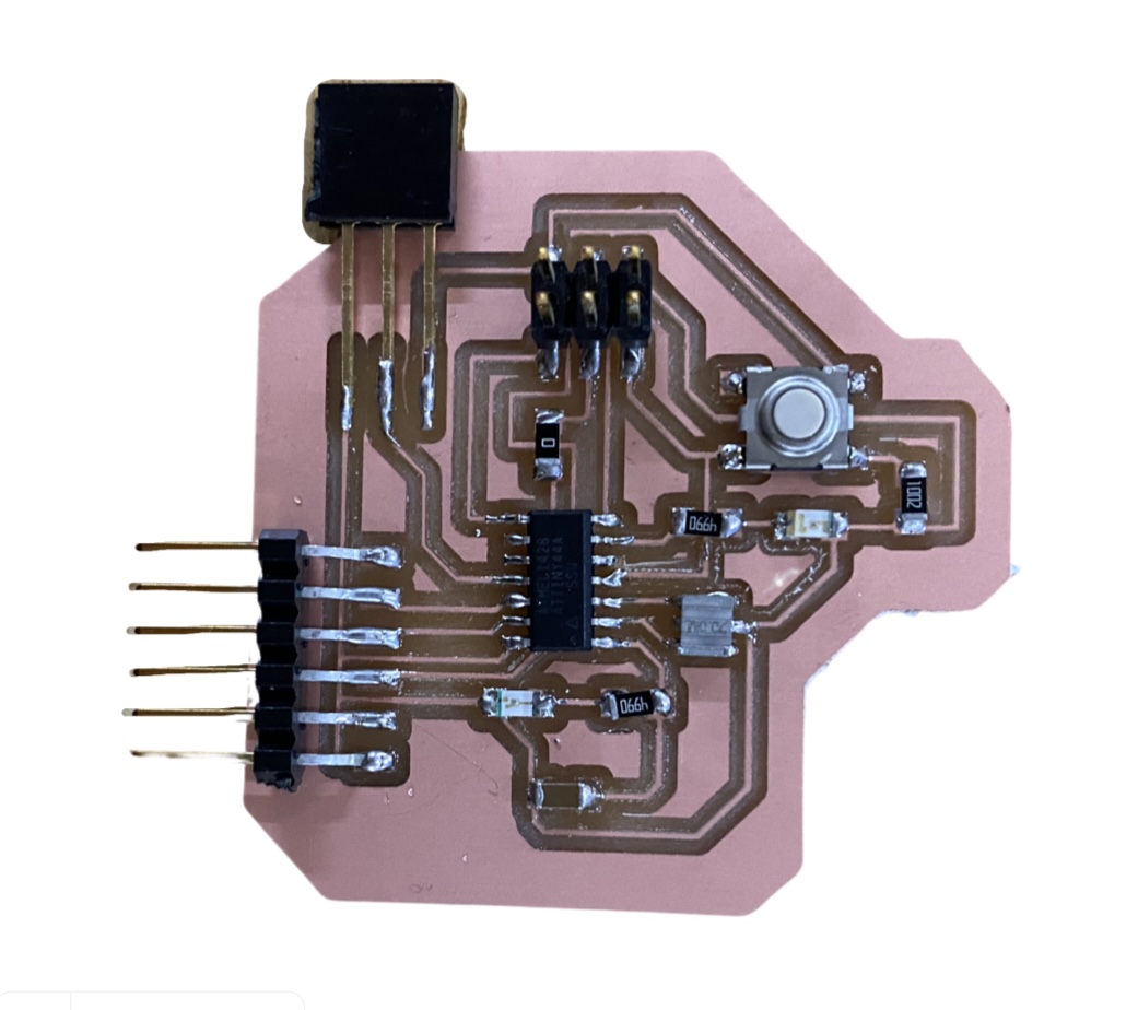
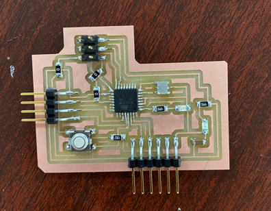
The boards were milled and soldered and the following image shows how the final soldered board.
Programming the boards
For programming both my boards, I used my USBTiny/FabISP. Since I had load seperate codes for the two boards, I programmed the boards separately.
First, I programmed my Input board which had the LM35 connected to it. The program can be seen below;
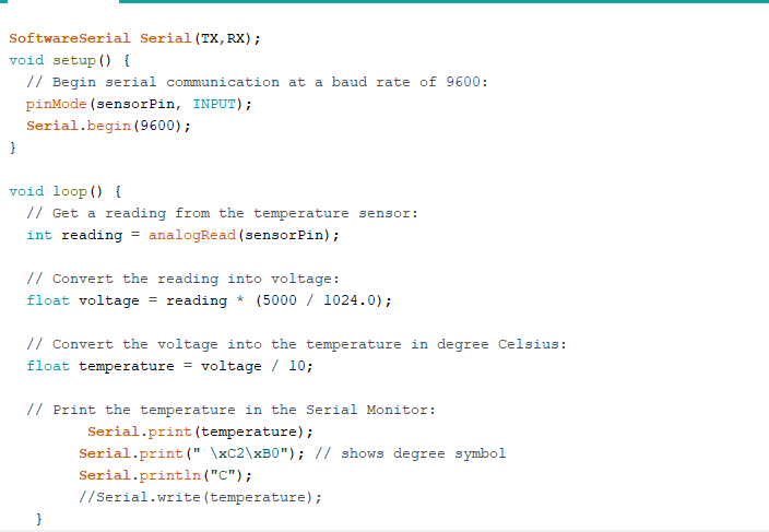
I used the Serial.print command to send the data read from the LM35 to the next board.
Next, I loaded the output board with the program to get the information to be displayed on the LCD. The program used is as shown below.
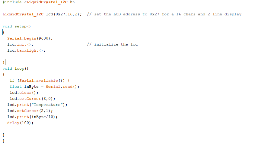
On this program I used the Serial.read command to get the data from the connected board to display on the LCD.
After programming both the boards, I connected the two boards. The Tx pin on the input board was connected to the Rx pin on output board and the Rx pin on input board was connected to the Tx pin of output board. The power was supplied to the board through the FabISP.
The complete connection can be seen below;
Result: Network and Communication Week