Task to be carried out this weekGroup Assignment
Action Plan
| Date | Work Allocation |
| 30th March | Lecture on Output devices by Prof. Neil |
| 31st March | lecture on week's assignment by the local instructor( Suhas Labade) and selection of output device to use (I selected I2C LCD) |
| 1st April | Board Design |
| 2nd April | Soldering |
| 3rd April | Connecting my board to I2C LCD |
| 4th April | Programming |
| 5th April | Documentation |
Introduction to output devices, I2C module and LCD
An output device is any electronic component that transforms the electric energy into another type of energy, such as light, sound or kinetic energy based on the command received from the microcontroller to which it is connected to.
Examples of Output devices;
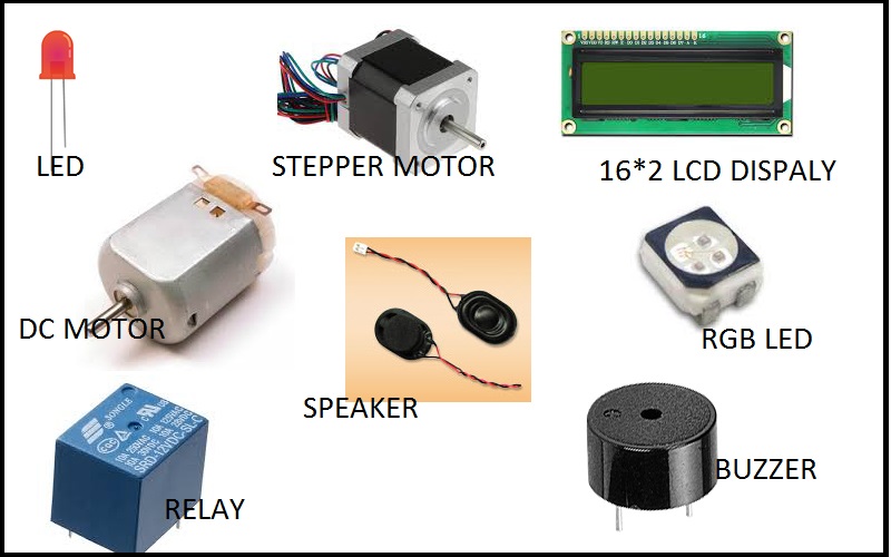
Picture Source: http://archive.fabacademy.org/fabacademy2017/fablabvigyanashram/students/53/assignments/Assignment10/index.html
For this week's assignment, we had to connect one output device to my microcontroller board and program it to do something.
Initially, I though of connecting an electric bulb through a solid state relay but I changed my mind and instead opted for an I2C Module for 16x2 (1602) Character LCD.
This was because, one of the output for my final project is an LCD. Before, I began with the assignment, I had to first ubderstand what an I2C module was and how it functioned.
What is an I2C module?
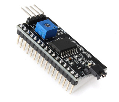
I2C Module has a inbuilt PCF8574 I2C chip that converts I2C serial data to parallel data for the LCD display. The module comes in 2 default addresss namely; 0x27 or 0x3F.
There is a contrast adjustment pot on the underside of the I2C module and we can use this to adjust the screen to display text correctly.
Features of I2C module
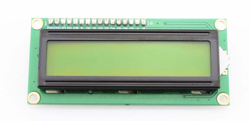
I2C Module for 16x2 (1602) Character LCD
I2C_LCD is an easy-to-use display module, It can make display easier. When you connect your microcontroller board directly to LCD, we require an 8 data pin connection while for connecting to an I2C we just need to make a 2 data pin connection.
This makes the wiring straight forward and board design work easier. The data pin connections required for the I2C_LCD display module are SDA and SCK.
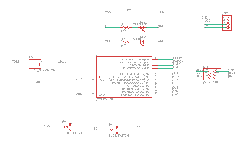
Board Design and soldering
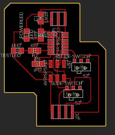
Initially I designed my board using an ATTiny 44 mincrocontroller. I connected a 4 pin header to be used for connecting to the I2C module. In ATTiny 44, the SDA and SCL pins are on pin number 7 and 9 (PA6 and PA4) respectively.
These pins are also used for connecting the MOSI and SCK for AVRISPSMD programmer header connection. Since, I am using AVRISPSMD programmer header for programming my board, I used a slide switch to switch the functionality of the pins as require.
Aside from that, I added 2 LED (one as power LED, and one test LED to check if my board is workig). I printed the board, soldered all the conponents and connected my board to the I2C_LCD module.
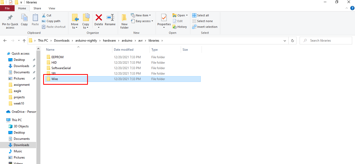
When programming the board for LCD display, I needed to download a separate library for I2C_LCD module named LiquidCrystal I2C. I downloaded the library from the arduino site https://www.arduino.cc/reference/en/libraries/liquidcrystal-i2c/.
Then I started with the programming but I found that the wire.h library which is available in the Arduino IDe doesn't work for AVR Tiny microcontrollers and I need to add a seperate library called TinywireM.h. I downloaded this library from this site https://www.arduino.cc/reference/en/libraries/tinywirem/
. I then loaded the code to display a text and after many trials and failures, I finally succeeded in compiling and loadiung the program to my board. However, the display was nowhere to be seen.
I thought maybe the LCD was broken, so to test it, I connected the LCD to arduino UNO board and loaded the same program, and WOALA!! it worked. So then, I consulted with my local instructor and he shared that similar issues were faced by other students who were using ATTiny 44 for as a microcontroller.
Thus, I had to created an entirely new board for the week.
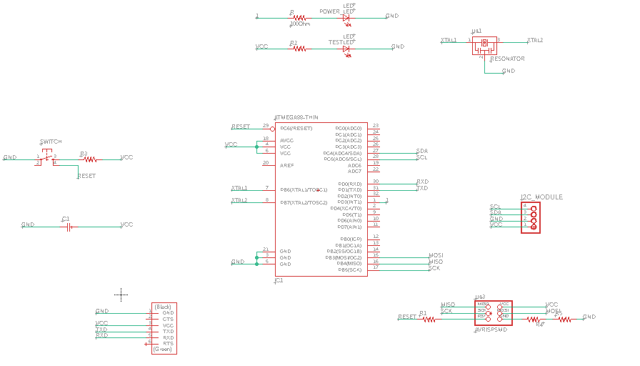
Since the ATTiny44 microcontroller failed to work for me, I started to design my board using ATMega328p. I choose this specific microcontroller because I am using the same for my final project board. Similar to how I designed my earier board, I added the following components to my board;
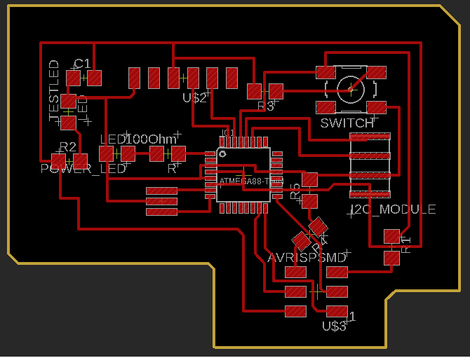
I used MITMods to created the .rml file for my board design and then milled using Roland SRM-20 machine. I then soldered the components and checked the connection using multimeter.
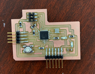
Final soldered board
Programming
After I was done with checking all the connections, I tested my board with a simple blink porgram. The test was successful so, I began with connecting my board to the I2C_LCD module and programming the board to display a simple text. However, I encountered an issue. Initially when I used the ATTiny44 microcontroller board, I had to replace the wire.h library with TinywireM.h library. I had to undo this to make the program functional for the ATMega328p board. Thus, I deleted the TinywireM.h library and replaced it with wire.h library in the arduino library folder.
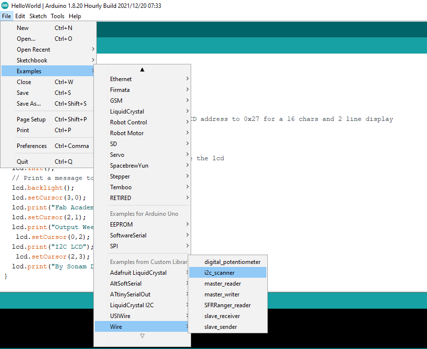
Next, I tried to load a simple display program to my board but I found that I had to find find the address of the I2C module. To do that I selected the I2C scanner program under the example provided in the Arduino IDE.
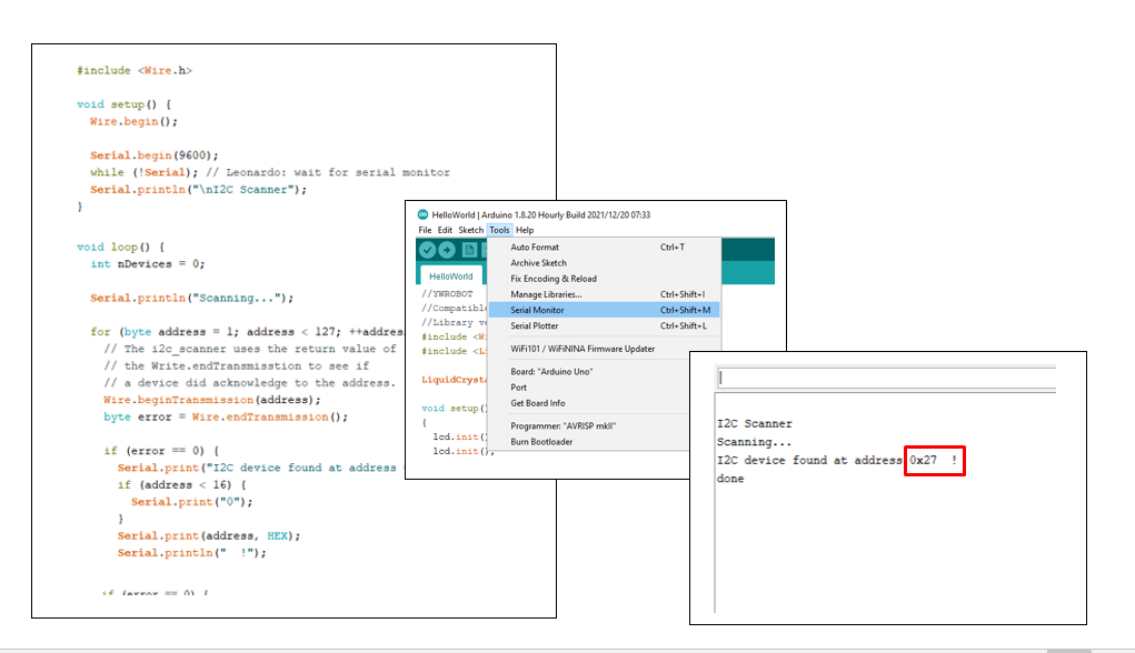
I compiled and loaded the program and checked the out put on the serial monitor under the tools option. The Address for the I2C was 0x27.
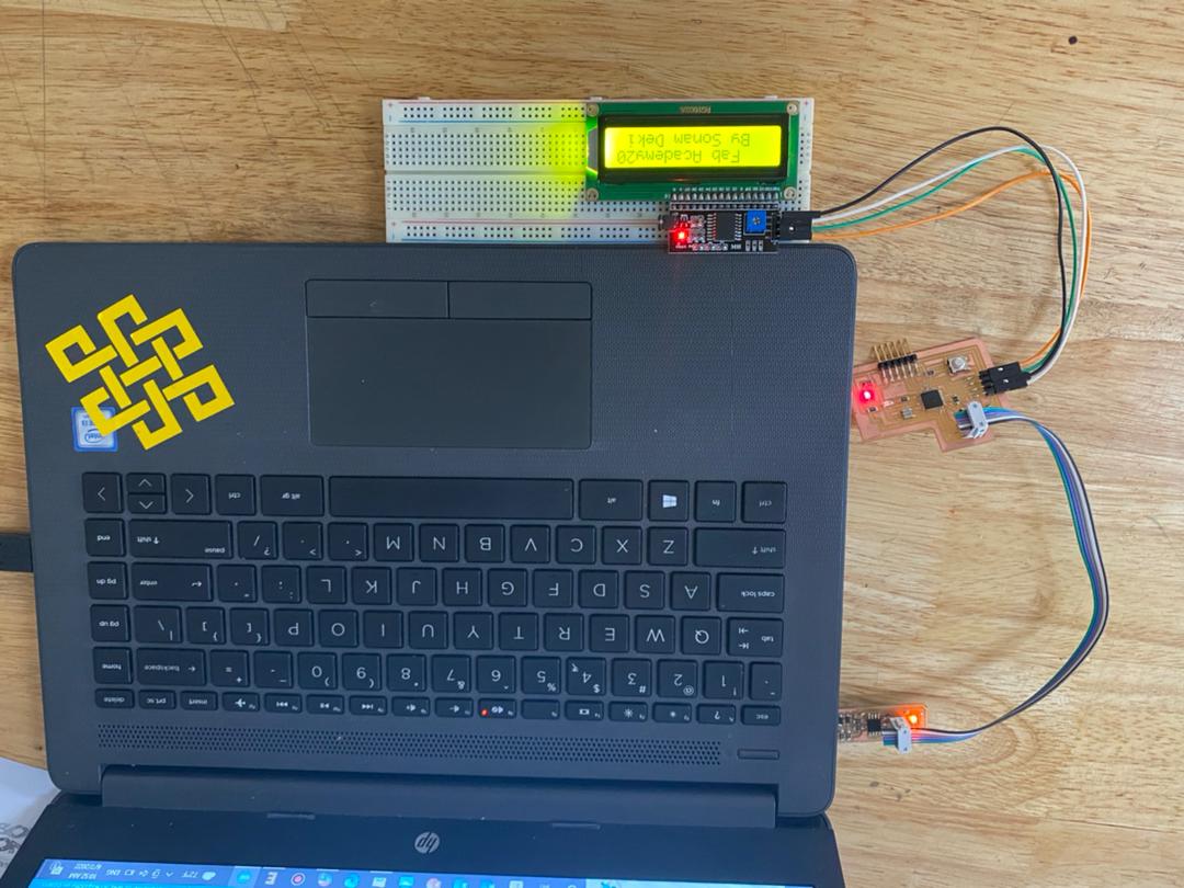
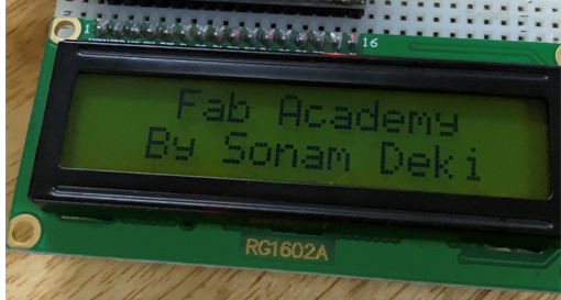
I added the I2C address in the program for displaying a text.
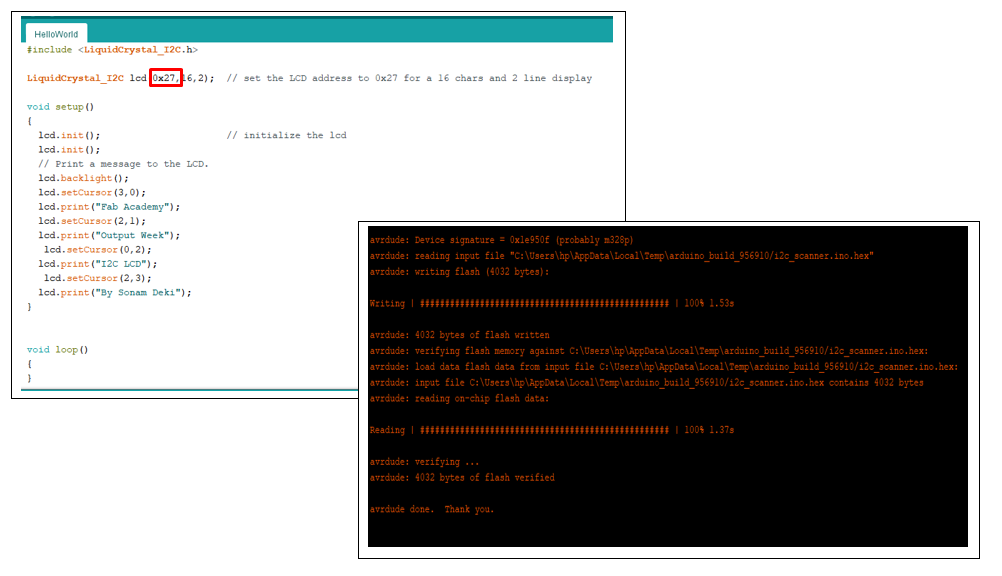
I loaded the porgram and it finally worked.
Week 10: Output devices
Project Files