Task to be carried out this weekGroup Assignment
Action Plan
| Date | Work Allocation |
| 20th April | Lecture on Input Devices by Prof. Neil |
| 21st April | Lecture on Input Device by Local Instructor and selection of Input device to use for the week |
| 22nd April | Board Design |
| 23rd April | Milling and Soldering the board |
| 24th April | Board Testing and Porgramming |
| 25th April | Board Testing and Programming |
| 26th April | Documentation |
Input Devices and Introduction to LM35
An input device is any hardware component that collects data from its surrounding and sends it to the microcontroller it is connected to.
Some examples of input devices are;
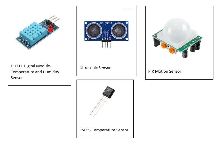
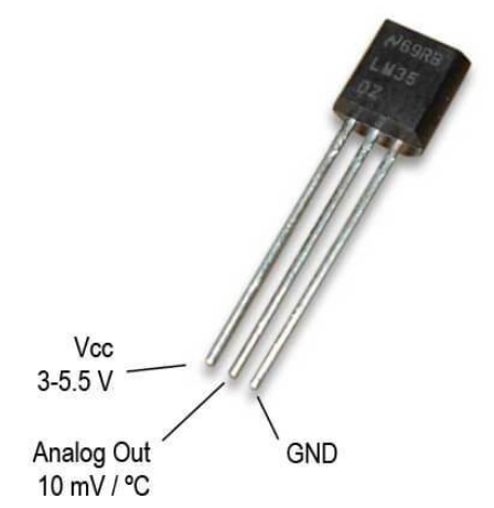
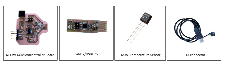
LM35-Temperature Sensor
The main task for this week's assignment was to add an input device to my microcontroller board and then use it to measure something. I choose the LM35 temperature sensor which is used for measuring the temperature of its surrounding.
I choose it because for my final project as well, I need to connect a temperature sensor to get the data for my kiln temperature.
Before using LM35 temperature sensor, I needed to understand what it was and how it functioned.
LM35 is a low cost temperature sensor that outputs an analog signal which is proportional to the instantaneous temperature. It gives the temperature readings in degree celsius and doesn't require any external caliberation. It has 3 pins out of which one is a data pin, one a power pin and one the ground pin.
Feature of LM35
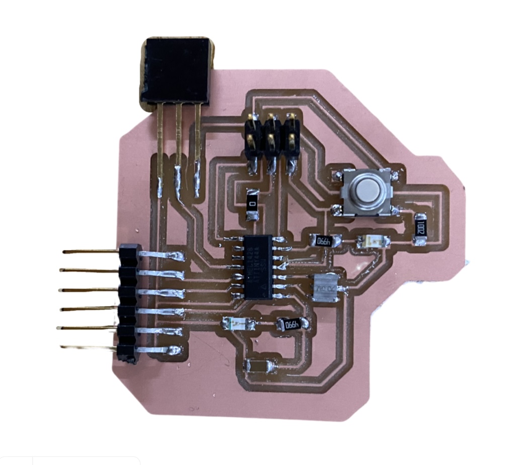
Board Design and soldering
I had to design one more board for this week's assignment. Initially, during my output week, I designed a board that kept provision for adding an input device but the board didn't work. So for the finalboard of the output week, I forgot to keep provision for input device. hence, I had to design another board for this week. I used the ATTiny44 microcontroller for this week. Because I faced alot of issues when using the ATTiny44 Microcontroller during my output week, I cross checked on internet as well as got suggestion form the local instructor before my board design. After I confirmed that ATTiny44 was compatable to be used with LM35, I started my board design. I kept the design of the board simple. I added the following components to my board;
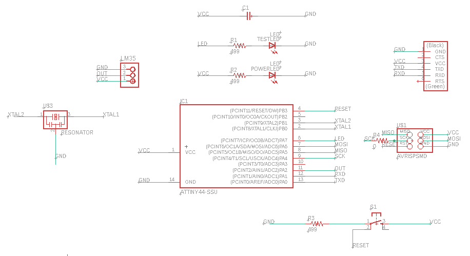
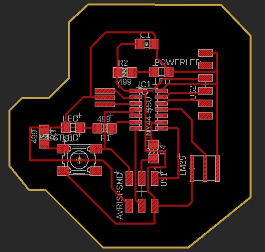
I connected pin 11 of my ATTiny 44 to the data pin of the LM35. Once the design was completed, I milled my board and soldered all the components on it.
Testing and Programming the board
After the board was completed, I started with the programming. I used the USBTiny/FabISP as a programmer to program my board and also connected the board to FTDI connector.
Before compiling the program LM35, I tested my board by uploading a simple blink program.
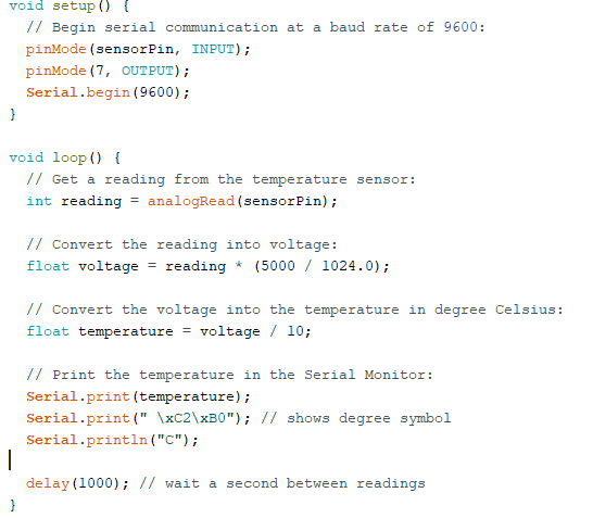
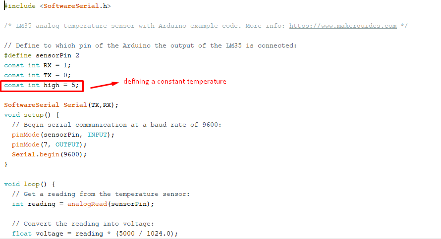
Once that worked, I tried a simple temperature display program. In the program, I had to define the LM35 datapin and the RX and TX pin numbers. I also had to add the SoftwareSerial.h library.
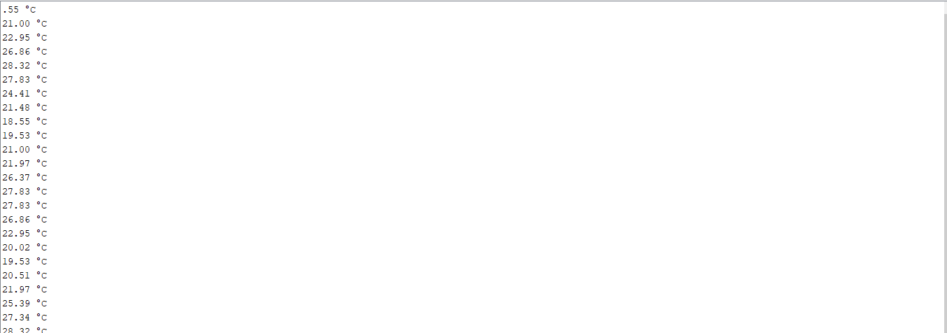
Output:
Next I tried another program, whereby the temperature read by the LM35 controlled the test LED on the board. To do that, I defined a constant temperature and programmed the board to turn off the LED if the
temperature read was below the defined constant and to turn the LED on of the temperature read was greater than the defined constant. The program successfully compiled and the board functioned as programmed.
Result: INPUT DEVICES
Project Files