
Final Project
Final Project Brain Storming
As discussed in the first week, I have deliberated upon several project ideas whereby I chose to make "Checkpost Management device", a device which
will basically help the guard/policeman to quickly detect the vehicle and passenger details as fast as possibel.
However, as weeks passed by, after consultations and project brain storming sessions with gab guru Mr. Take, I decided to work on
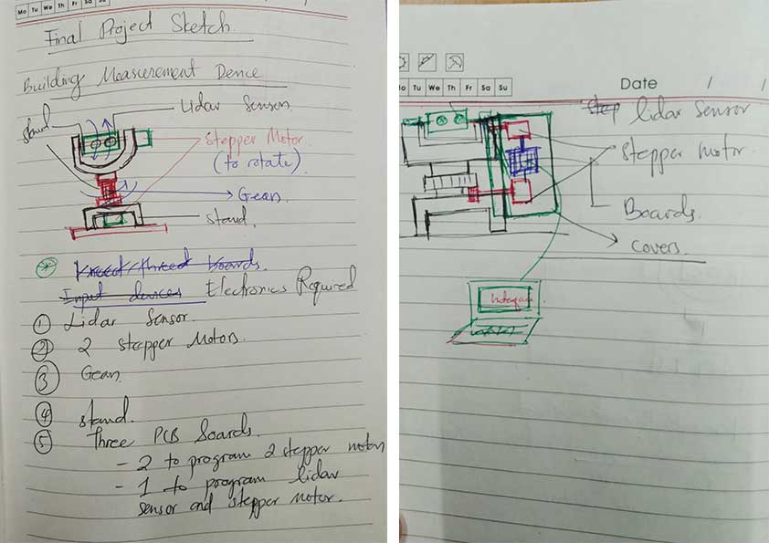
"Building Measurement Device", a device which will help the architects and engineers to do a quick scan and it will capture the details.
Needs Assessment
The project is intended to produce a low cost scanner which can be used by architects, engineers and other enthusiasts to quickly scan a space and will be able to make quick documentations. The ready made devices are available in the market, but the costs are very high. This device will be useful for documentations of heritage sites and other buildings which are beyond the reach of a physical verification, like in terrains.
Electronic Requirements
1. LiDAR sensor (TF Luna)
2. Servo Motors (2 numbers)
3. Gears (3D printed)
4. Atmega328p Microcontroller Board designs
5. Laptop
6. FTDI Cable
7. Buttons for reset
8. External power supply (jac)
The project is inspired from LIDAR SCANNER and lidarscanner.wordpress.com
Some other useful links and videos I referred are:
Computer Aided Design
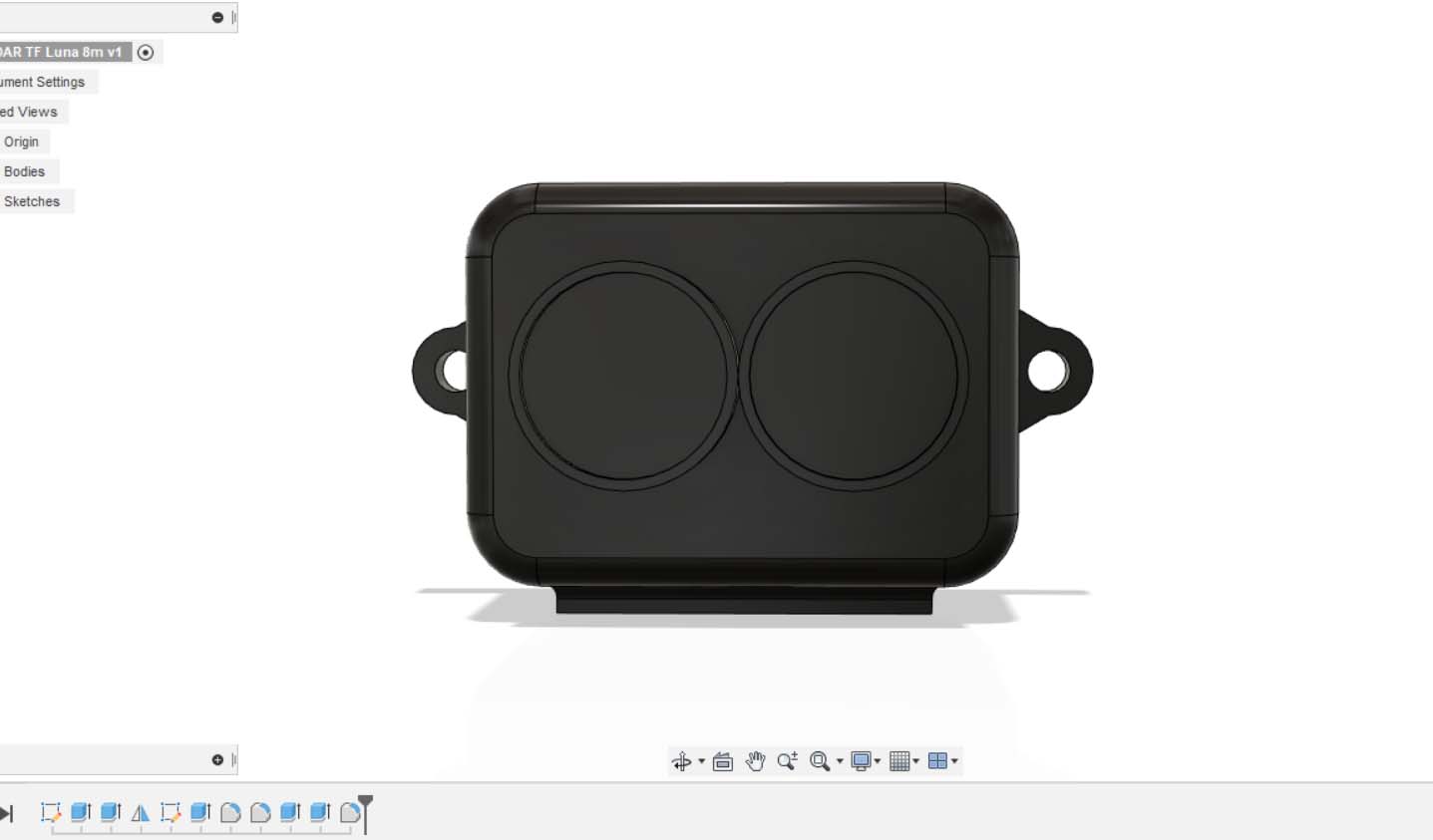
The LiDAR sensor I intend to use is a TF mini Lidars.
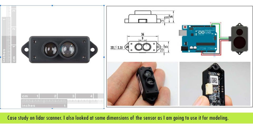
However after much discussions with the instructors, I have decided to work with LiDAR TF Luna 8m. Therefore, I modelled my sensor with Fusion 360. I referred the dimensions from Cytron Marketpalce.
The dimenisions given in are as follows:
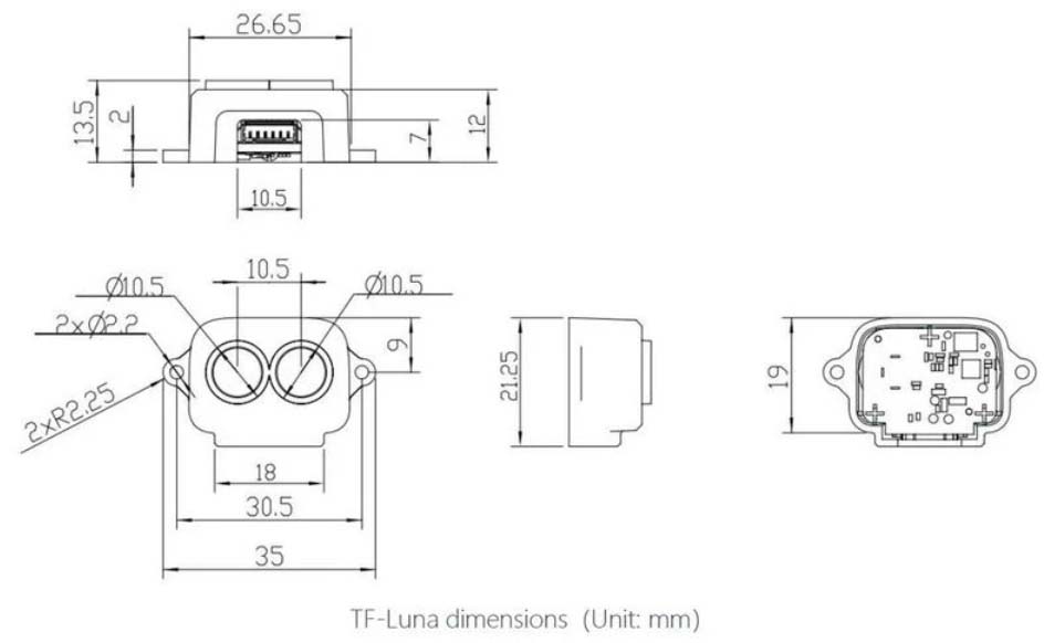
I modelled my sensor with fusion360
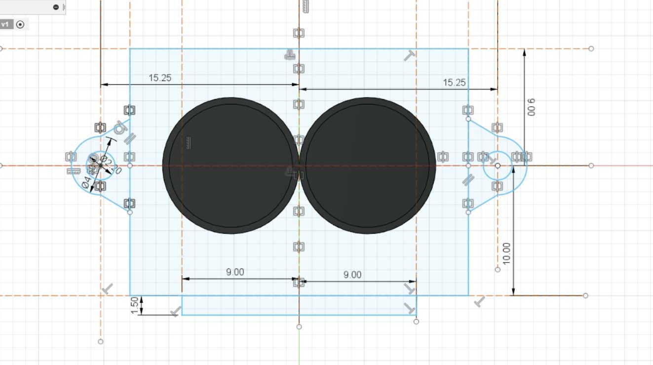
Final LiDAR sensor model is as follows:
After much discussion with my project guide, I finalized my design. I used two Servo motors for my X and Y-orentation.
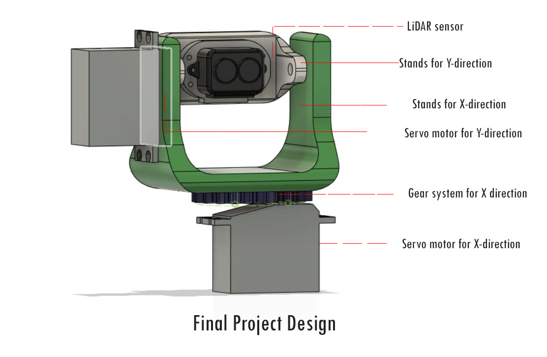
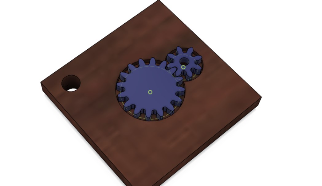
It is a simple prototpe with gear systems to rotate the LiDAR sensor to collect the data. However, the design is quite complicated. Even a simple box cover needs a detailed design which is possible with 3D printing only. Most of the body parts of the scanner is 3D printed including the gears. The cover design details is as seen below:
The final design with the casings can be seen below:
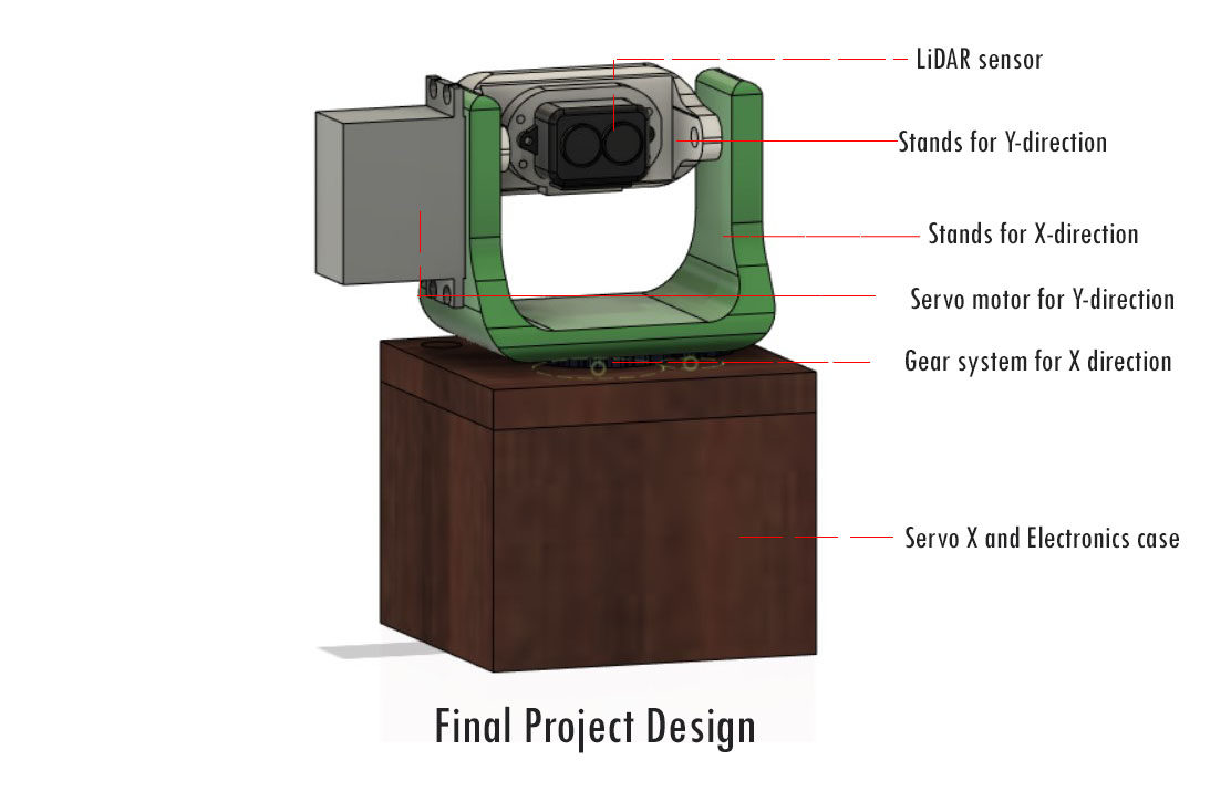
You can also view the web version of my model here:
The design is shown below:
Download my model here.
Electronics Design
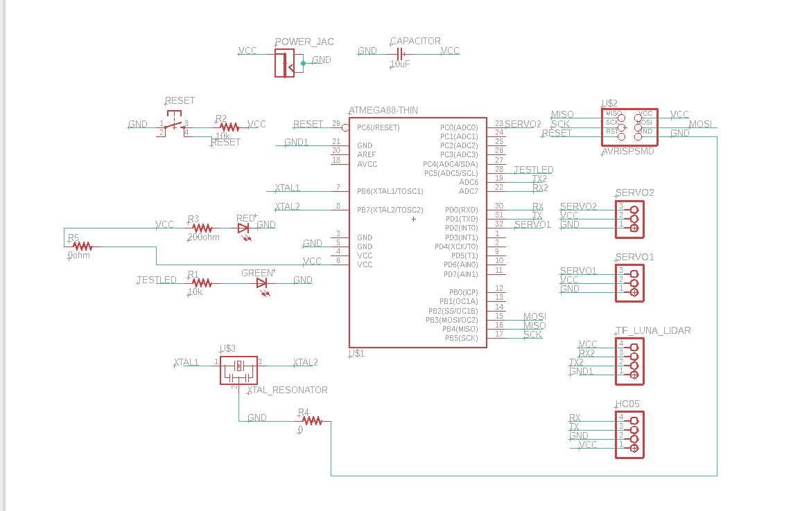
I have decided to use the Atmega328p microcontroller to design my main board which is described in my Output week. However, since I have not considered the order of pins as described there.
My schematic for the project is as presented below:
Final board design is as shown below: I have changed the pin for test LED from pin 28 to pin 2 and few other pins so that it is more convenient to route in the board design.
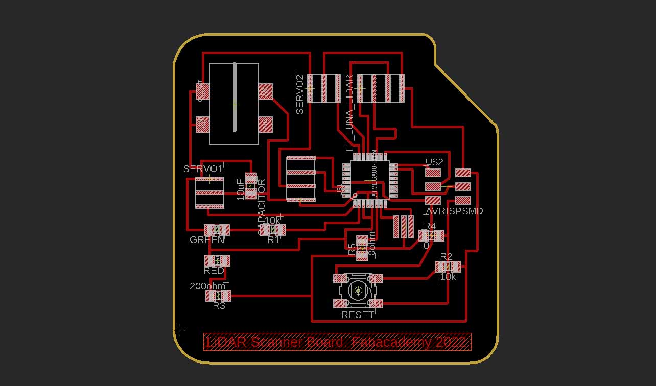
One sad thing I did today is that, I forgot to save my design and exited when prompted to save it. Therefore, I have to design my board once again.
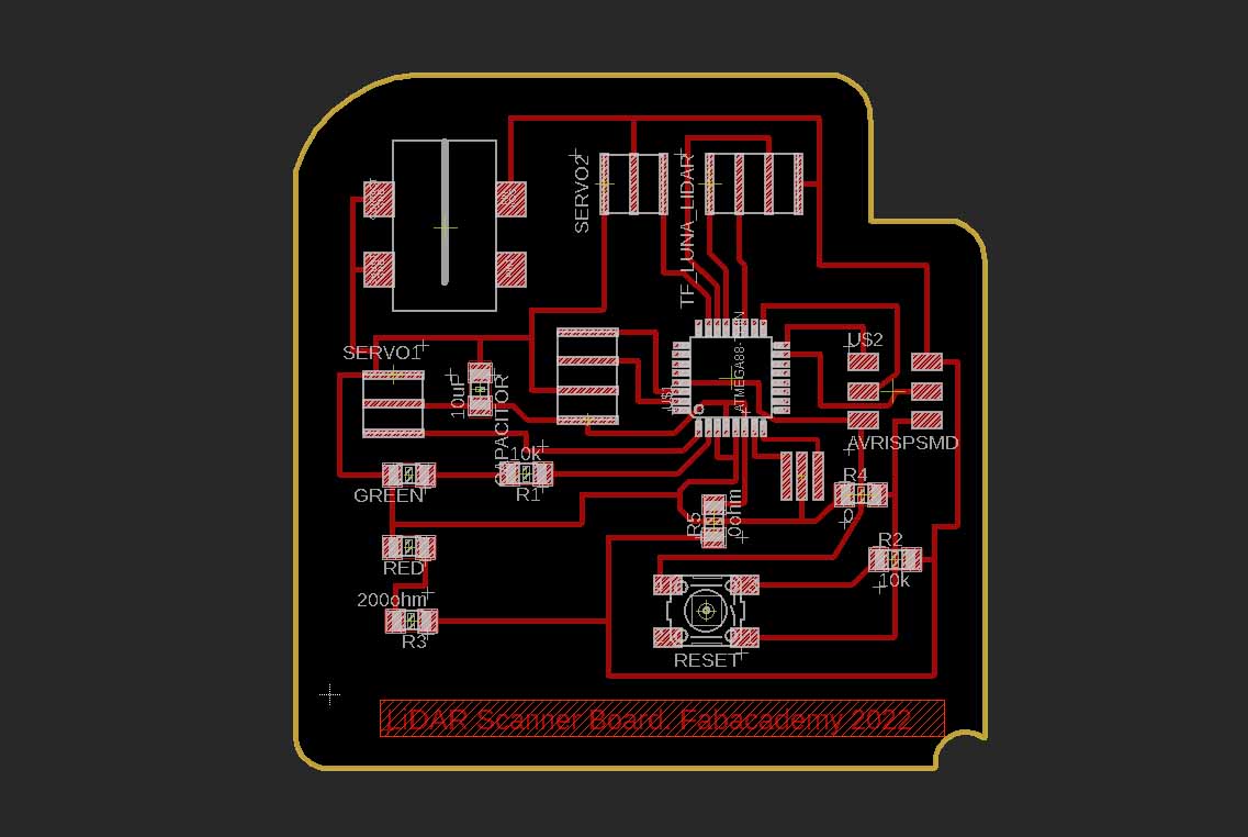
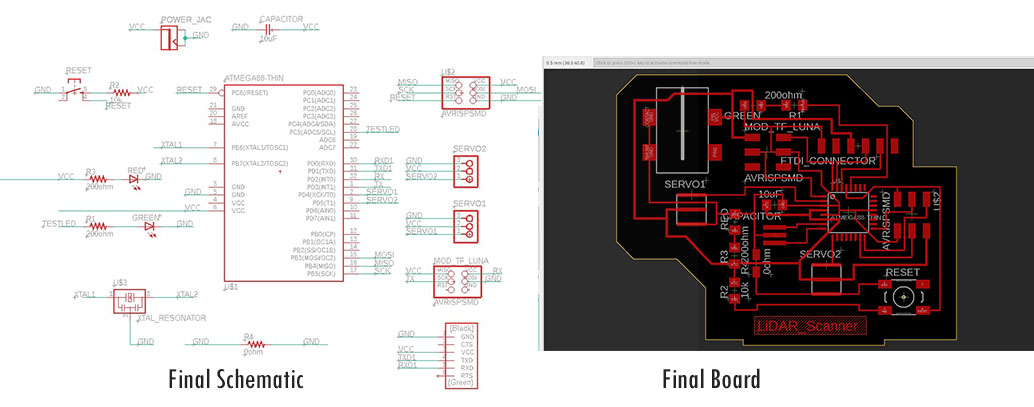
Finally, my instructor came and we had a fruitful discussion about my project on 17th May. He instructed me to re-design my boards considering all the components required with specific pin numbers. For example, LiDAR sensor requires Tx and RX pins as it works with the principle of serial communications. Therefore, I redesigned my boards. With this, I ditched my earlier boards. This schematic and board is more accurate for my project requirements.
Component Soldering
Sodering Atmega328p chip is wuite challenging as the pins are designed really closed to each other. However, with the help of my instructor Mr. Suhas, I was able to successfully solder my components.
As usual, before soldering it is important for us to clear and clean the workstation, assemble all the components required and then start soldering.
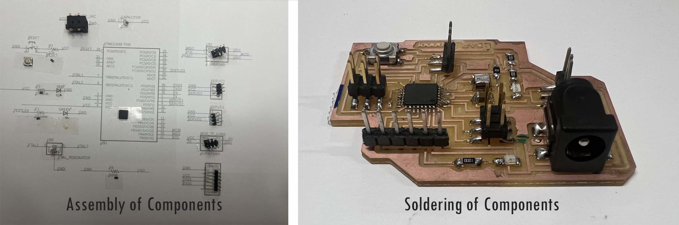
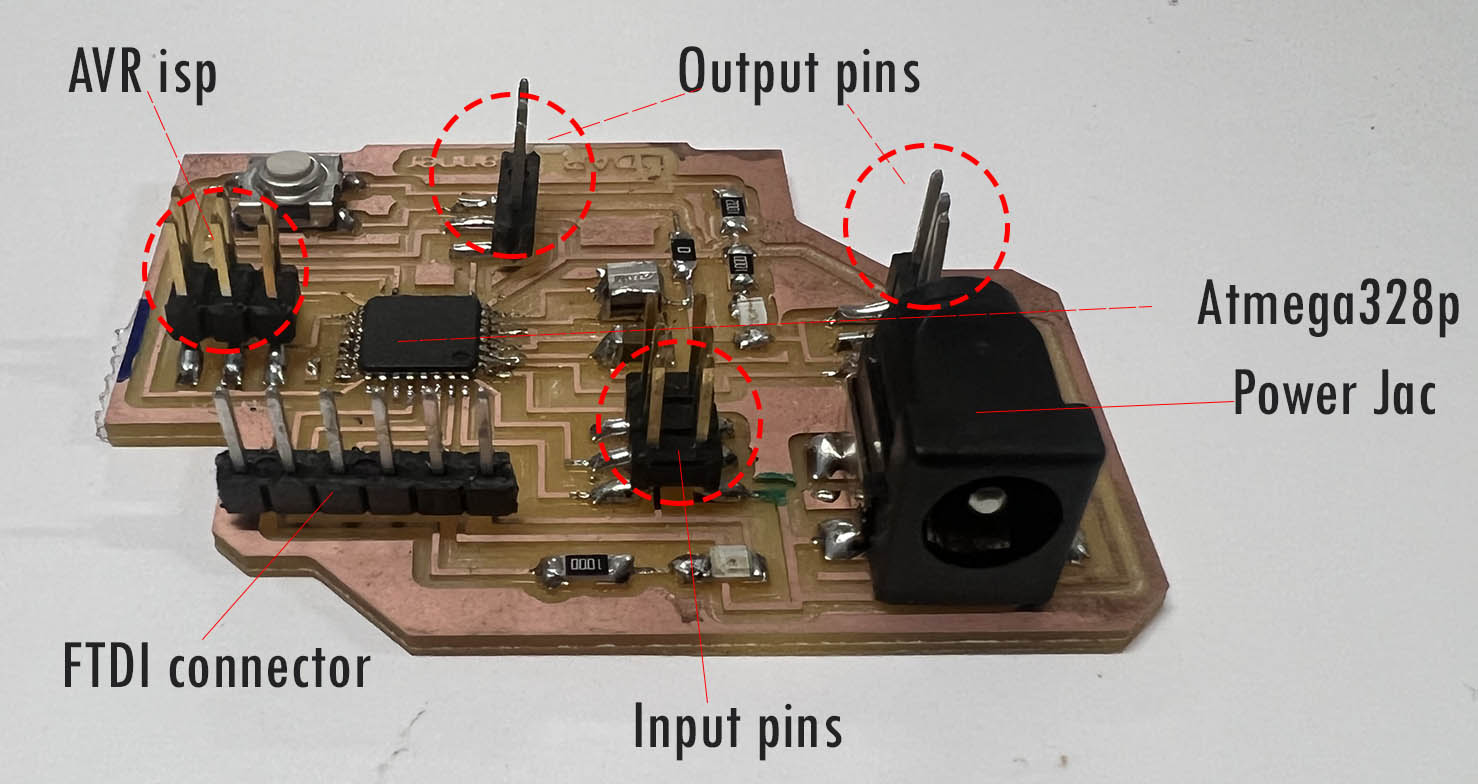
The description of the pin outs I have kept as follows:
Computer Controlled Cutting
In a computer controlled Cutting week, we used Laser Cutter and Vinyle Cutter as a subtractive manufacturing process. For my final project, I used the Laser Cutter to fabricate the cover of my sensor and the Vinyle Cutter to fabricate my logo.
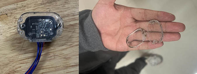
Lasser Cutting Process
I fabricated the cover of my LiDAR sensor TF Luna in Lasser Cutter GCC Lasser Pro. The design is done in Fusion360 as you can see in the CAD model.
The parameters are as follows:
The result is as shown below:
Vinyl Cutting Process
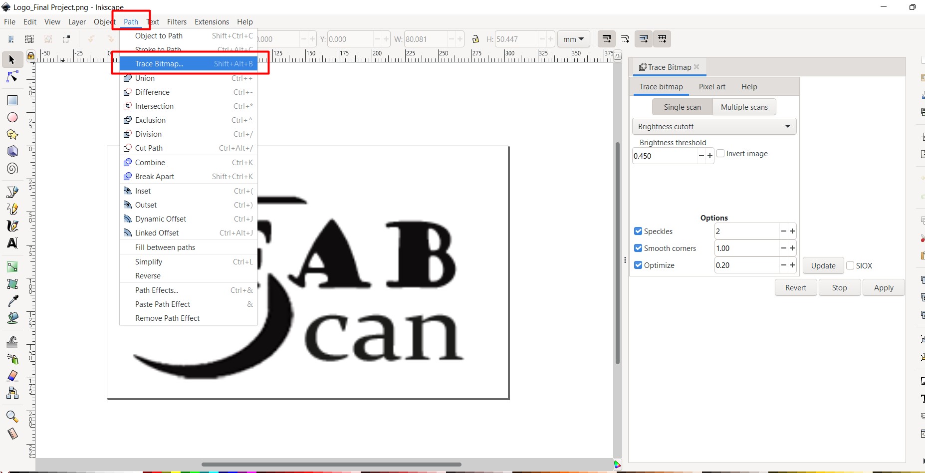
I designed a logo of my project in Photoshop which I then exported it to SVG format after opening it in Inkscape.
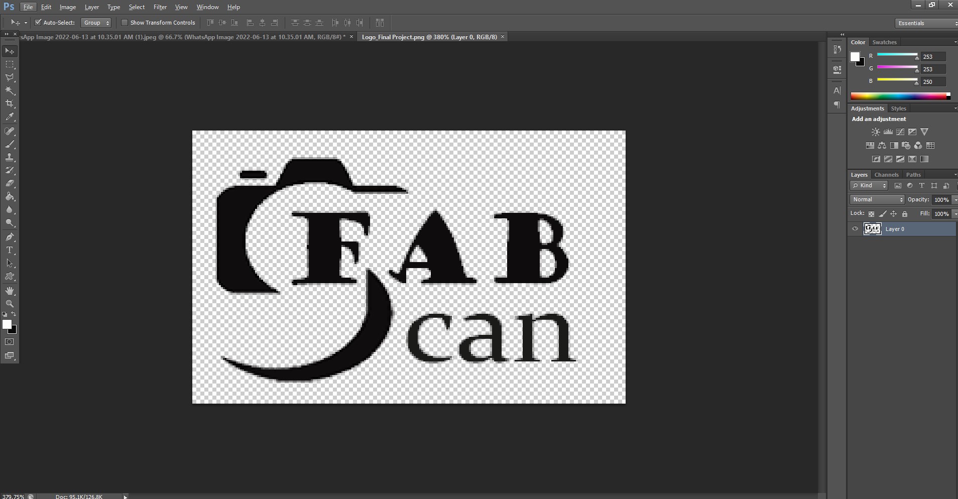
The image is traced as a Bitmap as shown below in Inkscape before saving it in SVG format. It is important to save the image in .svg format as the EasyCut studio which is a software used for Vinyl Cutting reads that format.
Finally, the file is cut in Vinyl Cutter after setting it in EasyCut studio.
I used the force of 150gf to cut my Logo as per my previous assignmnets. The process and the result is as shown below:
3D Printing
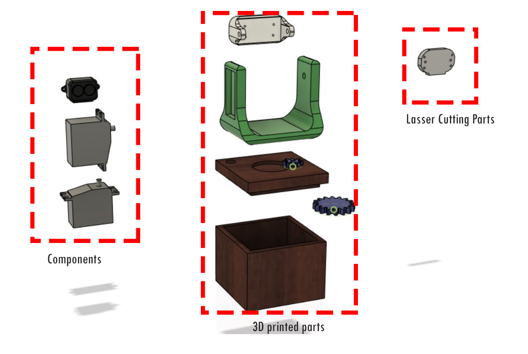
For my final project, most of the body parts are 3D printed as shown below:
I exported my parts in .stl format from fusion360. Then, it is imported to makerbot software to do settings for 3D printing in MakerBot SKETCH 3D printer.
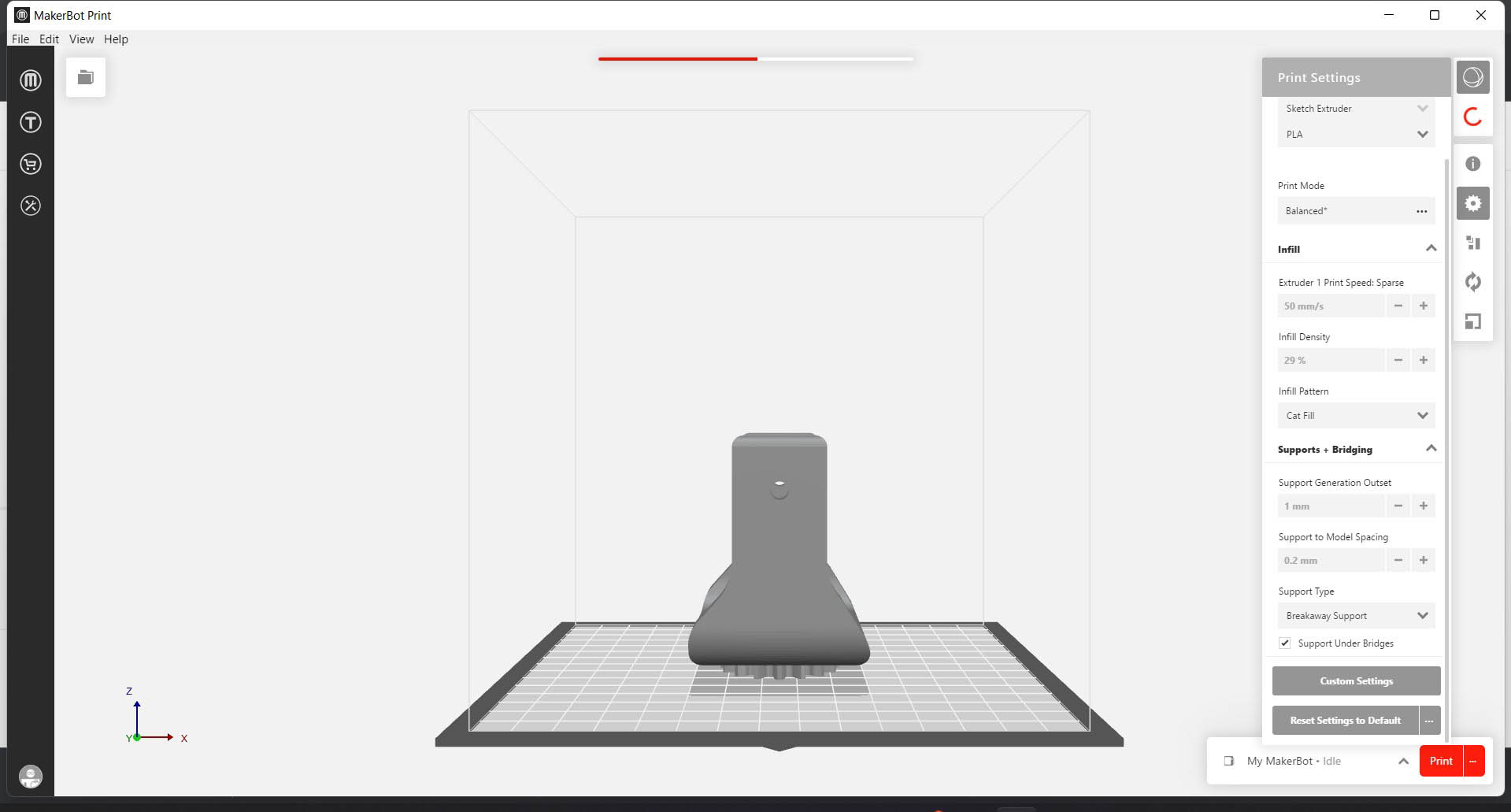
Basic settings I kept for my 3D printing process are as follows:
1. Support type: breakaway support and Support under bridges.
2. Infill density: 50%
3. Infill Pattern: Cat fill
4. Print mode: balanced.
5. Support to model spacing: 0.2mm
6. Support generation outset: 1mm
The process can be seen below in a short video
You can see the images of the 3D printed parts below:

Input Device
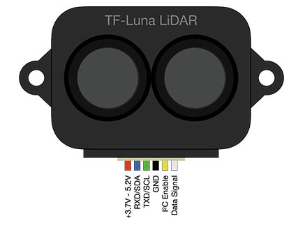
For my project, the input device I used is a LiDAR sensor TF Luna. Accroding to velodynelidar.com, Lidar (light detection and ranging) uses eye-safe laser beams to “see” the world in 3D, providing machines and computers an accurate representation of the surveyed environment. It's working can be shown in the following image:
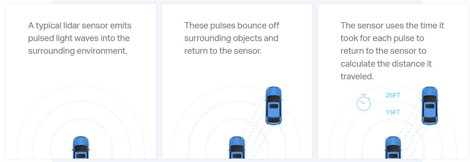
Repeating the above process many times per second creates a precise, real-time 3D map of an environment called a point cloud. This technology is used in self nevigating cars.
Details about the TF Luna LiDAR sensor can be seen here in my Input week's assignment.
Attached below is the test I ran with TF Luna:
The sensor perfectly reads the distance, strength and the temperatures.
Output Device
I need to use two servo motors as my Output devices. I have documented the about the servo motors and its working in my Output week's assignment.
However, for my final project, I need to make a mechanics of two servo motors which will tilt and pan my LiDAR sensors. The test of servo mechanism is shown below:
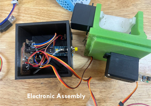
Component Assembly
I have designed my body parts in such a way that it press fits. However, I also did keep the slots for the external power supply, FTDI cable and button which needs to be controlled from the external.
The electronic assemblage is shown below:
Final project outcome is shown below: a product of sweats and many sleepless nights.
Embedded Programming
As explained earlier, my project consists of the composition of two servos for pan and tilt. The servos must work in such a way that as the pan servo rotates 180 deg, a tilt servo must tilt 2 deg.
As the servos Pan, a LiDAR sensor must be activated and scanning of spaces must be done. Therefore, I need to program my Servos to Pan and Tilt, and then scan in horizontal direction.
The Concept
The conceptual framework of this project is inspired from Travis Ledo's project. The project consists of Arduino & Java (Processing) side. The Arduino side handles all the servo movements and gets measurement readings from the Lidar sensor. The Java side does the spherical to cartesian points conversion and renders them in 3D. They communicate with each other over the serial port which consists of Rx and Tx.
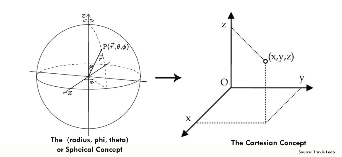
The Mathematics
As the two servos Pan (Phi) and then Tilt (Theta), the reading we get from the Lidar sensor will become the Radius. Which means that device itself would be at point (0,0,0). Therefore, aach data set sent from the Arduino to the Java program consists of these three numbers (radius, phi, theta) with leading zeroes for consistency.
From here, we convert these Spherical points to Cartesian(x, y, z) so we can properly plot them in our Java program.
The formulae for this conversion is:
However, I have noticed that we have to swap the some values of X, Y, Z in java code to -ve and some to +ve. That's because the computer coordinate system is different as well. For example, in computer coordinates, the x goes horizontal not y. Y positive goes down, not up. Therefore, we need to modify these values in order to get the correct place.
The Programming
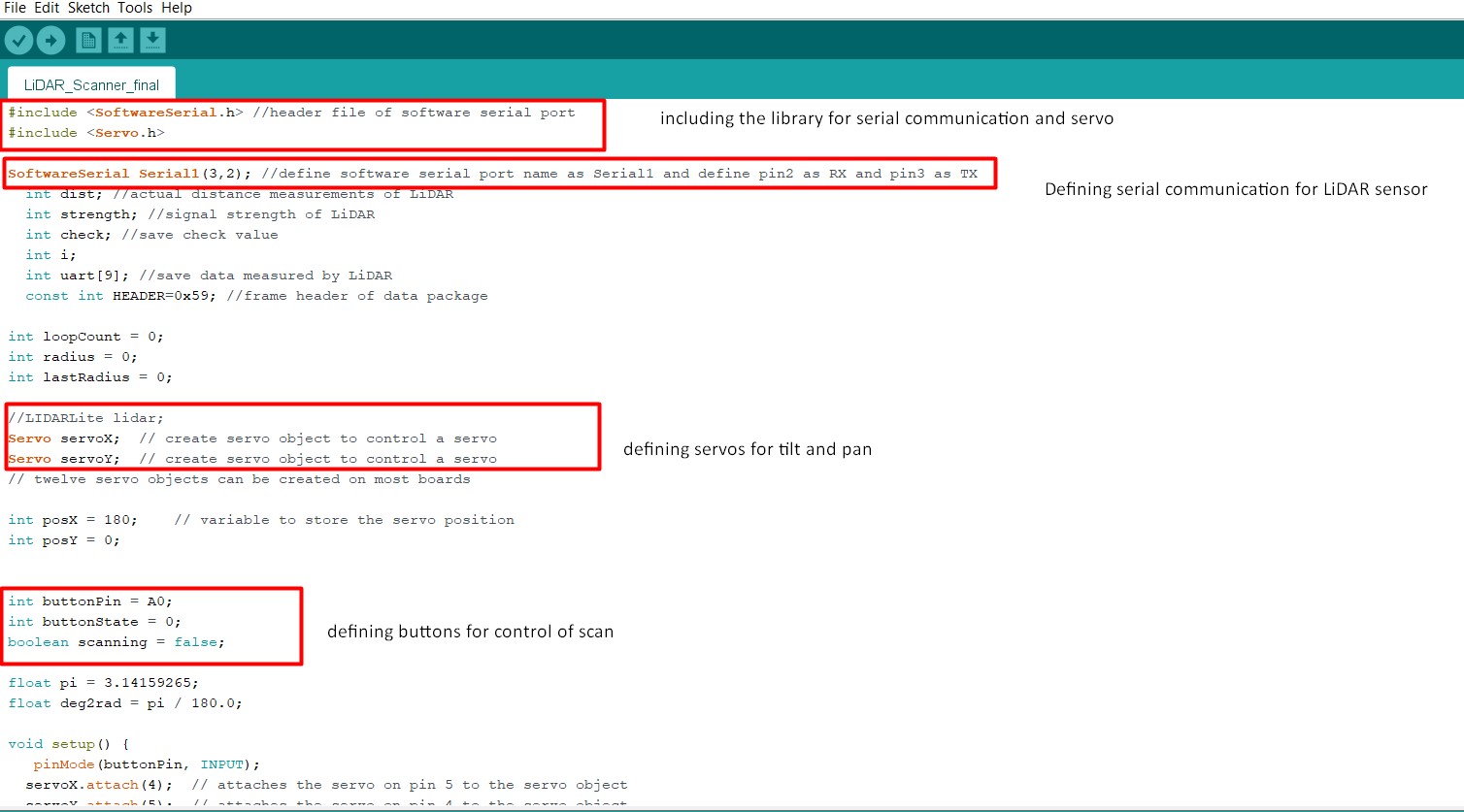
First, we set up variables and include library for servos and serial communication.
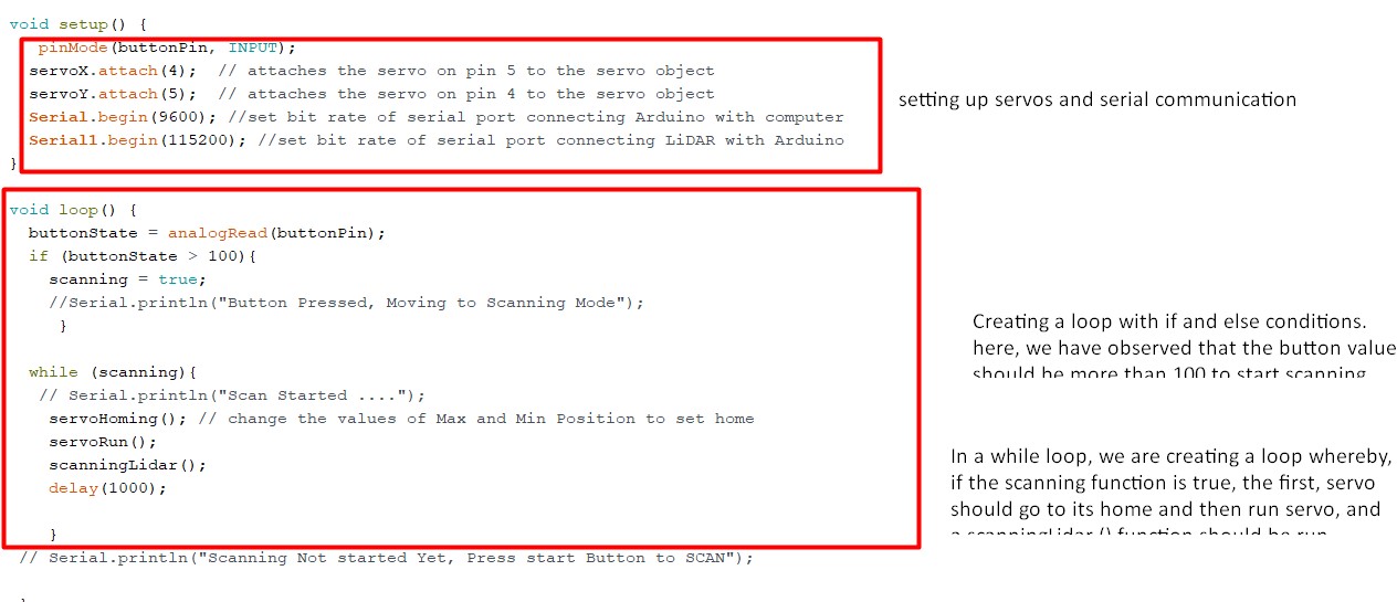
Then, we set up servos and create a loop for the project. In the loop, we call functions.
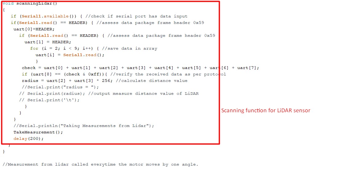
The functions are set as shown below: The three most important function I used is the servoHoming, servoRun, and scanningLidar.

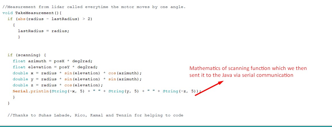
Finally, I have gave function for the mathematics behind the LiDAR scanning.
The Arduino code is also given below for the reference.
                                // LidarScanner code
                                // The original codes was created by  http://www.qcontinuum.org/lidar
                                //Modified by Sangay Penjor for fabacademy 2022 final project from Bhutan
                                #include <SoftwareSerial.h> //header file of software serial port
                                #include <Servo.h>

                                SoftwareSerial Serial1(3,2); //define software serial port name as Serial1 and define pin2 as RX and pin3 as TX
                                  int dist; //actual distance measurements of LiDAR
                                  int strength; //signal strength of LiDAR
                                  int check; //save check value
                                  int i;
                                  int uart[9]; //save data measured by LiDAR
                                  const int HEADER=0x59; //frame header of data package

                                int loopCount = 0;
                                int radius = 0;
                                int lastRadius = 0;

                                //LIDARLite lidar;
                                Servo servoX;  // create servo object to control a servo
                                Servo servoY;  // create servo object to control a servo
                                // twelve servo objects can be created on most boards

                                int posX = 180;    // variable to store the servo position
                                int posY = 0;


                                int buttonPin = A0;
                                int buttonState = 0;
                                boolean scanning = false;

                                float pi = 3.14159265;
                                float deg2rad = pi / 180.0;

                                void setup() {
                                   pinMode(buttonPin, INPUT);
                                  servoX.attach(4);  // attaches the servo on pin 5 to the servo object
                                  servoY.attach(5);  // attaches the servo on pin 4 to the servo object
                                  Serial.begin(9600); //set bit rate of serial port connecting Arduino with computer
                                  Serial1.begin(115200); //set bit rate of serial port connecting LiDAR with Arduino
                                }

                                void loop() {
                                  buttonState = analogRead(buttonPin);
                                  if (buttonState > 100){
                                    scanning = true;
                                    //Serial.println("Button Pressed, Moving to Scanning Mode");
                                     }

                                  while (scanning){
                                   // Serial.println("Scan Started ....");
                                    servoHoming(); // change the values of Max and Min Position to set home
                                    servoRun();
                                    scanningLidar();
                                    delay(1000);

                                    }
                                 // Serial.println("Scanning Not started Yet, Press start Button to SCAN");

                                 }
                                // function called at the begining of buttonPush to go to HOME position
                                void servoHoming(){
                                  posX = 180;  //homepoint/startpoint X
                                  posY = 0; //homepoint/startpoint Y
                                  servoX.write(posX);
                                  delay(200);
                                  servoY.write(posY);
                                  delay(200);
                                }

                                //Main code to run the motors and the scanning
                                void servoRun(){
                                  for (posY = 0; posY <= 120; posY += 2) { // goes from 0 degrees to 180 degrees // in steps of 1 degree
                                    for (posX = 0; posX <= 180; posX += 3) { // goes from 180 degrees to 0 degrees
                                      servoX.write(posX);              // tell servo to go to position in variable 'pos'
                                     // Serial.println(posX);
                                      servoY.write(posY);              // tell servo to go to position in variable 'pos'
                                     // Serial.println(posY);
                                     scanningLidar();
                                     delay(100);                       // waits 200 ms for the servo to complete one scan
                                    }
                                  //Serial.println("One Set of XY Scan Complete");  //prints everytime one Axis scan is complete
                                  }
                                 // Serial.println("All Sets of XY Scan Complete");
                                  scanning = false;
                                  servoHoming();
                                  //Serial.println("All Scan Complete, Moving to HOME");
                                }

                                //scanning function called by servoRun Funtion.
                                void scanningLidar()
                                {
                                   if (Serial1.available()) { //check if serial port has data input
                                   if(Serial1.read() == HEADER) { //assess data package frame header 0x59
                                    uart[0]=HEADER;
                                      if (Serial1.read() == HEADER) { //assess data package frame header 0x59
                                        uart[1] = HEADER;
                                          for (i = 2; i < 9; i++) { //save data in array
                                            uart[i] = Serial1.read();
                                            }
                                       check = uart[0] + uart[1] + uart[2] + uart[3] + uart[4] + uart[5] + uart[6] + uart[7];
                                       if (uart[8] == (check & 0xff)){ //verify the received data as per protocol
                                       radius = uart[2] + uart[3] * 256; //calculate distance value
                                       //Serial.print("radius = ");
                                      // Serial.print(radius); //output measure distance value of LiDAR
                                      // Serial.print('\t');
                                        }
                                      }
                                    }
                                    //Serial.println("Taking Measurements from Lidar");
                                    TakeMeasurement();
                                    delay(200);
                                  }
                                }

                                //Measurement from lidar called everytime the motor moves by one angle.
                                void TakeMeasurement(){
                                  if (abs(radius - lastRadius) > 2)
                                    {
                                      lastRadius = radius;
                                      }


                                  if (scanning) {
                                    float azimuth = posX * deg2rad;
                                    float elevation = posY * deg2rad;
                                    double x = radius * sin(elevation) * cos(azimuth);
                                    double y = radius * sin(elevation) * sin(azimuth);
                                    double z = radius * cos(elevation);
                                    Serial.println(String(-x, 5) + " " + String(y, 5) + " " + String(-z, 5));
                                    }
                                  }

                                  //Thanks to Suhas Labade, Rico, Kamal and Tenzin for helping to code
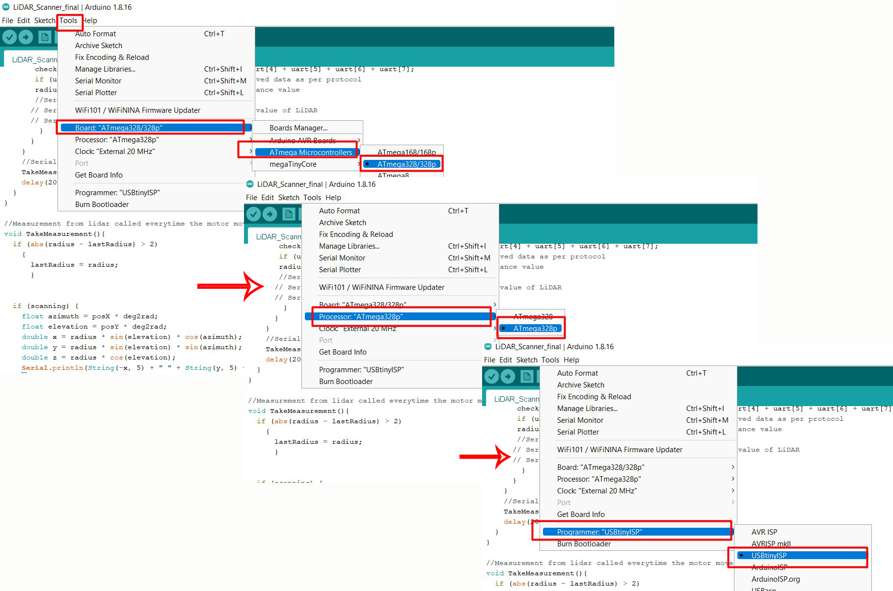
Before, uploading the codes, follow the steps below: I used the USBtiny or fabISP to program my atmega328 board.
Programming result is shown below:
Interface & Application Programming and Communication
As discussed earlier, the Arduino side handles all the servo movements and gets measurement readings from the Lidar sensor. Which is then serial sent to Java side for rendering. Therefore, the Java side is the result of the system we designed earlier.
The values from the Arduino is sent to the Java (here we use Processing) to render through serial communication. The steps of communication is as following:
The Programming
The Processing is used as a java IDE to plot the points sent by the arduino. Therefore, following code is used:
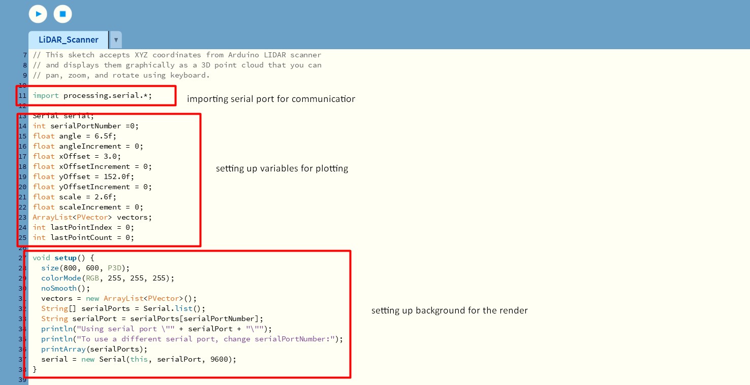
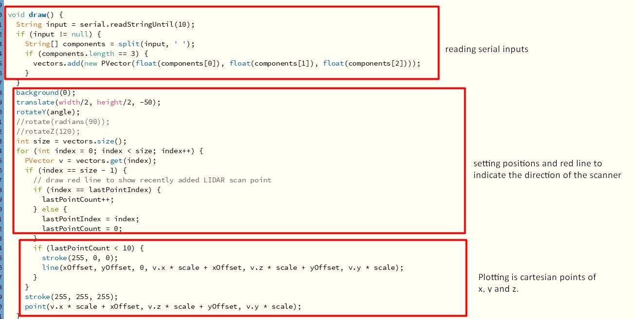
The code for the reference is:
                            // LidarScanner.pde Processing sketch
                            // http://www.qcontinuum.org/lidar
                            //moified on 12th June 2022 by Sangay Penjor for fabacademy project
                            // Load sketch into Processing, available from:
                            // https://processing.org/

                            // This sketch accepts XYZ coordinates from Arduino LIDAR scanner
                            // and displays them graphically as a 3D point cloud that you can
                            // pan, zoom, and rotate using keyboard.

                            import processing.serial.*;

                            Serial serial;
                            int serialPortNumber =0;
                            float angle = 6.5f;
                            float angleIncrement = 0;
                            float xOffset = 3.0;
                            float xOffsetIncrement = 0;
                            float yOffset = 152.0f;
                            float yOffsetIncrement = 0;
                            float scale = 2.6f;
                            float scaleIncrement = 0;
                            ArrayList<PVector> vectors;
                            int lastPointIndex = 0;
                            int lastPointCount = 0;

                            void setup() {
                              size(800, 600, P3D);
                              colorMode(RGB, 255, 255, 255);
                              noSmooth();
                              vectors = new ArrayList<PVector>();
                              String[] serialPorts = Serial.list();
                              String serialPort = serialPorts[serialPortNumber];
                              println("Using serial port \"" + serialPort + "\"");
                              println("To use a different serial port, change serialPortNumber:");
                              printArray(serialPorts);
                              serial = new Serial(this, serialPort, 9600);
                            }

                            void draw() {
                              String input = serial.readStringUntil(10);
                              if (input != null) {
                                String[] components = split(input, ' ');
                                if (components.length == 3) {
                                  vectors.add(new PVector(float(components[0]), float(components[1]), float(components[2])));
                                }
                              }
                              background(0);
                              translate(width/2, height/2, -50);
                              rotateY(angle);
                              //rotate(radians(90));
                              //rotateZ(120);
                              int size = vectors.size();
                              for (int index = 0; index < size; index++) {
                                PVector v = vectors.get(index);
                                if (index == size - 1) {
                                  // draw red line to show recently added LIDAR scan point
                                  if (index == lastPointIndex) {
                                    lastPointCount++;
                                  } else {
                                    lastPointIndex = index;
                                    lastPointCount = 0;
                                  }
                                  if (lastPointCount < 10) {
                                    stroke(255, 0, 0);
                                    line(xOffset, yOffset, 0, v.x * scale + xOffset, v.z * scale + yOffset, v.y * scale);
                                  }
                                }
                                stroke(255, 255, 255);
                                point(v.x * scale + xOffset, v.z * scale + yOffset, v.y * scale);
                              }
                              angle += angleIncrement;
                              xOffset += xOffsetIncrement;
                              yOffset += yOffsetIncrement;
                              scale += scaleIncrement;
                            }
After uploading the Arduino codes to the board, the USBtiny is removed and a FTDI cable is connected for serial communications. An external power of 5V is needed to get a good result.
The scanning process is quite slow. It takes almost an hour to get a good scan of the space I scanned.
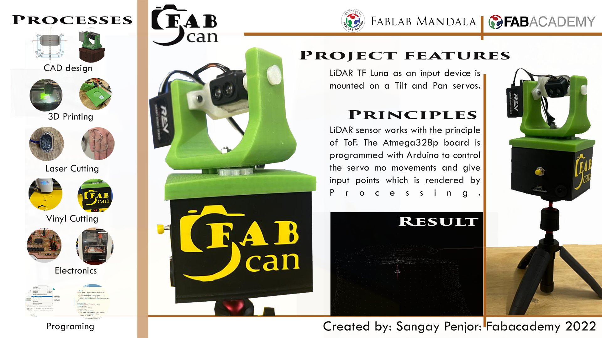
Project Presentation
I presented my project on 13th June, 2022. The summary slide of my project is shown below:
The one minute video I presented to Prof. Neil and fab ecosystem is shown below:
Project file downloads
Download project schematic design here
Download project board design here
Download png outline here
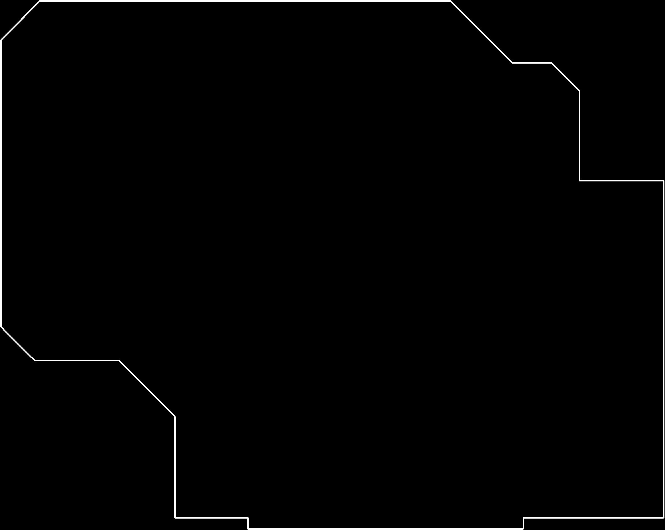
Download png trace here
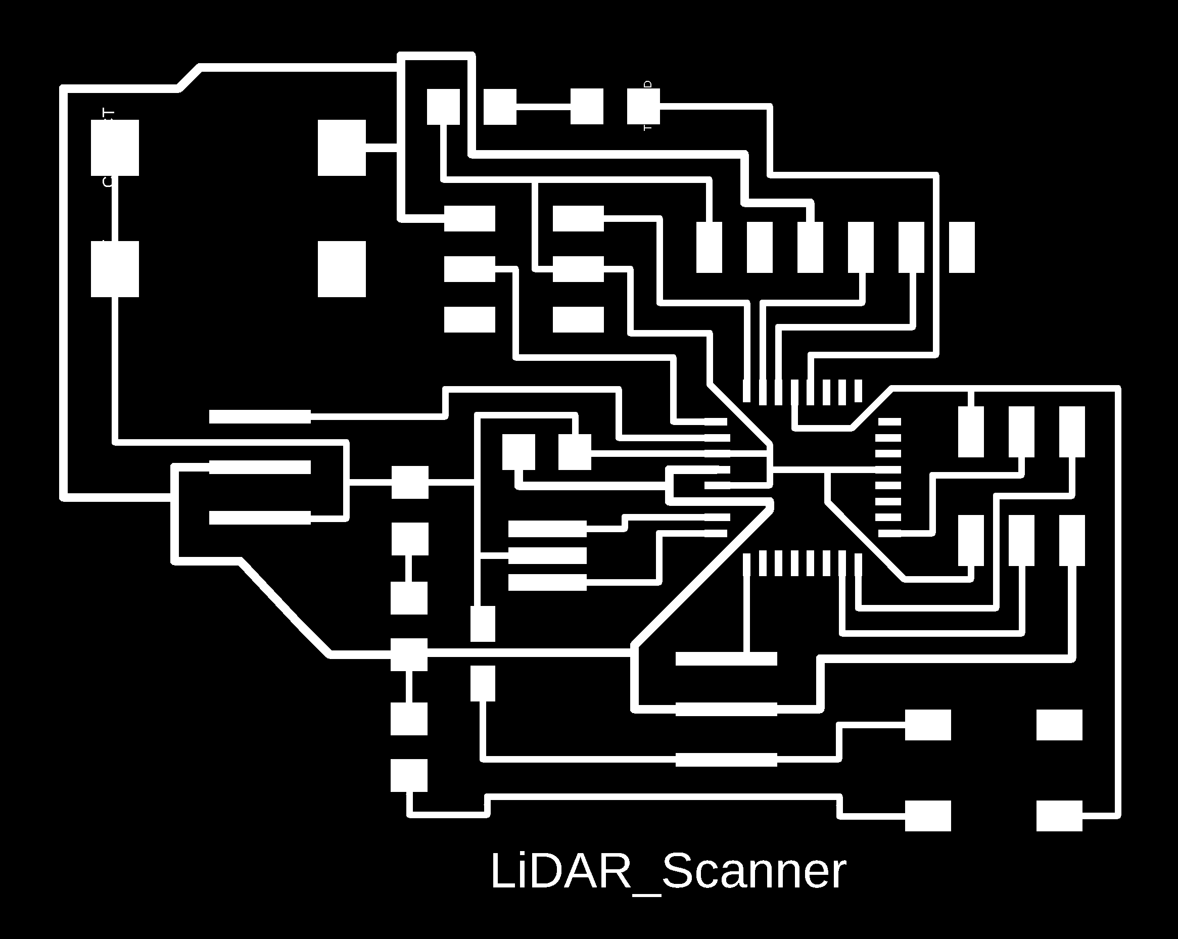
Download project 3D design in fusion360 here
Download logo in .svg/.png/.psd file here
Download project Arduino source code here
Download project processing source code here