
Input Device
Group Assignment
Group Assignment:
probe an input device's analog levels and digital signals,
The group work that our group has done can be seen here
Individual Assignment:
measure something: add a sensor to a microcontroller board that you have designed and read it.
Board Design with ATtiny1614
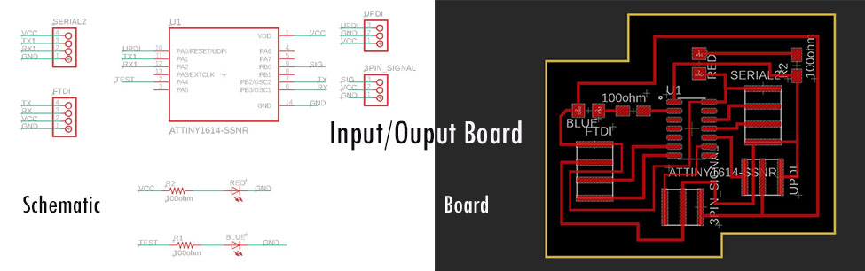
I also designed a board for my input devices. It is a very simple board with power LED, test LED and input and output pins. I also kept povisions for UPDI connectors. The shematic and board design is as follows:
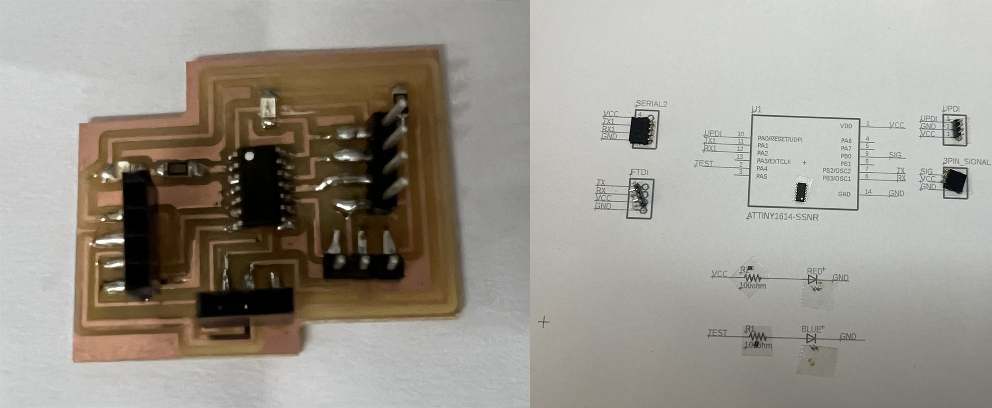
I assembled the components soldered it. I supplied VCC and GND with Arduino uno board and my Power LED red glows, which means my board and soldering is correct.
Setting up Arduino IDE for ATtiny1614 board.
In order to set up Arduino IDE for ATtiny1614 board and UPDI programmer, I referred here. and pasted the following url in the preferences.
http://drazzy.com/package_drazzy.com_index.json
File -> Preferences, enter the above URL in "Additional Boards Manager URLs"
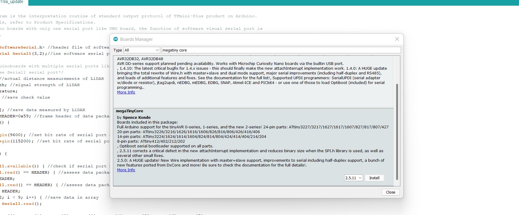
Tools -> Boards -> Boards Manager...
Select "megaTinyCore by Spence Konde" and click "Install".
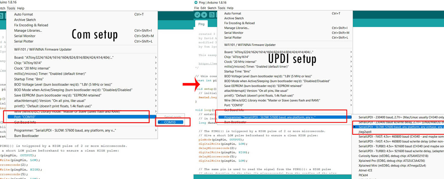
 After, that make the following setting under tools.
1. Set up ATtiny1614 board:
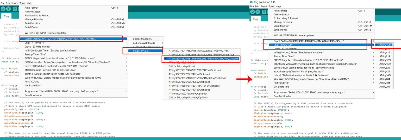
2. Set up of COM and UPDI.
However, when I tested my board with blink code, following errors kept on coming.
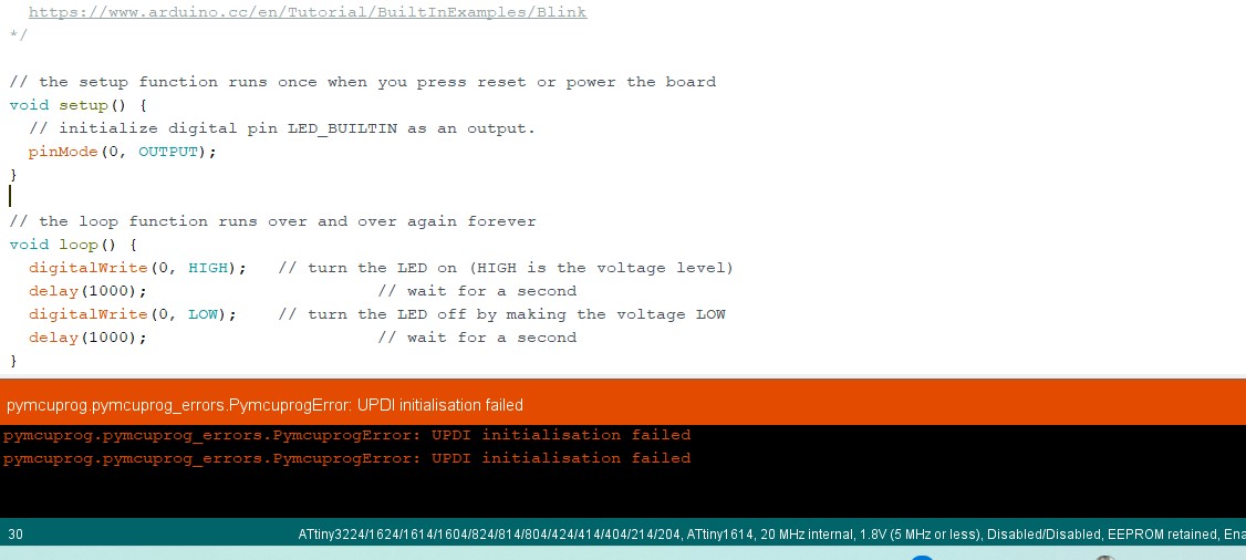
Therefore, I have to solder my board once again. Its such a hectic journey with my ATtiny1614. Finally, I soldered my board again.
For this week's assignment, I want to use TF Luna LiDAR sensor and Ultrasonic sensor. I am using TF Luna LiDAR sensor because my final project uses this sensor.
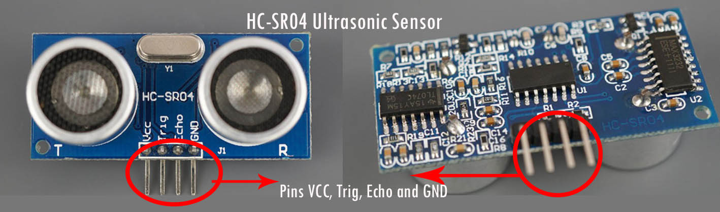
HC-SR04 Ultrasonic Sensor
According to randomnerdtutorials.com, The HC-SR04 ultrasonic sensor uses sonar to determine the distance to an object. This sensor reads from 2cm to 400cm (0.8inch to 157inch) with an accuracy of 0.3cm (0.1inches), which is good for most hobbyist projects. In addition, this particular module comes with ultrasonic transmitter and receiver modules.
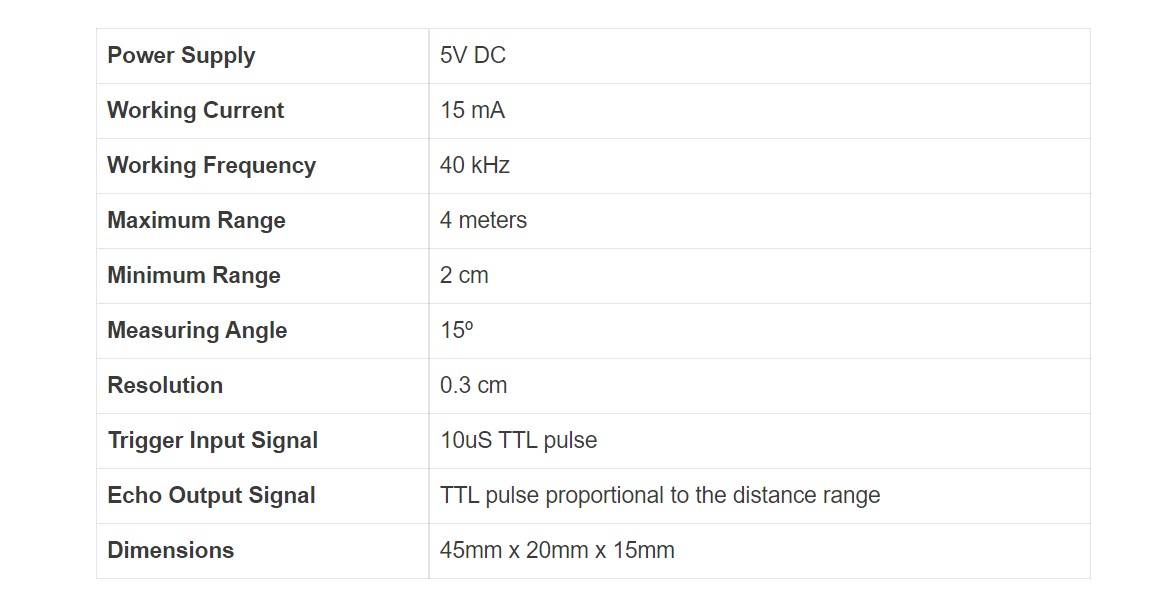
The key features and specs of the HC-SR04 ultrasonic sensors are as shown below:
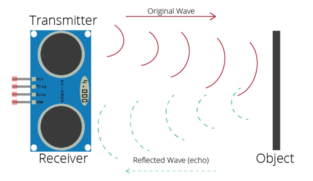
Working Principle
The ultrasonic sensors uses sonar to determine the distance to an object. It works as explained below:
The ultrasound transmitter (trig pin) emits a high-frequency sound (40 kHz), which travels through the air. On finding an object,
it bounces back to the module which is then recieved by the Echo Pin. The echo pin is the ultrasonic receiver.
The image below depicts the this principle. Image source: randomnerdtutorials.com
Programming HC-SR04 Ultrasonic Sensor
To program the Ultrasonic sensor, I used UPDI FT230XS Programmmer board I made it in Week 10's assignment, and ATtiny1614 board I designed for this week.
I referred the pinout diagram of ATtiny1614 for Arduino iDE here. The image is also attached below:
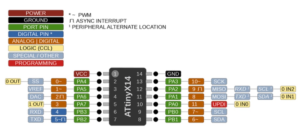
I used Tom Igoe's codes to program the sensor. I connected VCC, GND and Pin 9 of my board with VCC, GND and Trig Pin of the sensor. The following image is the explaination of the codes.
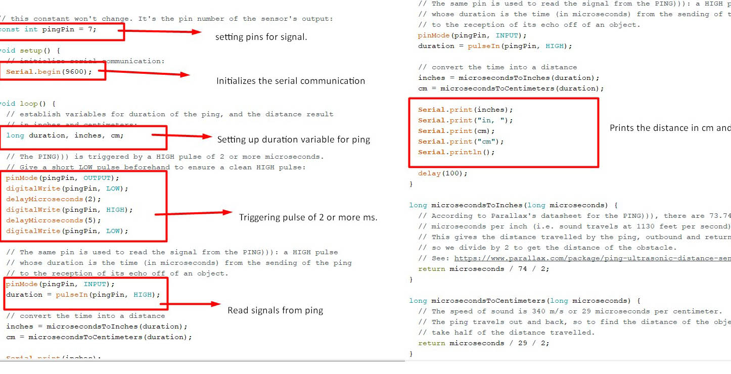
Ref the following codes:
                                // this constant won't change. It's the pin number of the sensor's output:
                                const int pingPin = 7;

                                void setup() {
                                  // initialize serial communication:
                                  Serial.begin(9600);
                                }

                                void loop() {
                                  // establish variables for duration of the ping, and the distance result
                                  // in inches and centimeters:
                                  long duration, inches, cm;

                                  // The PING))) is triggered by a HIGH pulse of 2 or more microseconds.
                                  // Give a short LOW pulse beforehand to ensure a clean HIGH pulse:
                                  pinMode(pingPin, OUTPUT);
                                  digitalWrite(pingPin, LOW);
                                  delayMicroseconds(2);
                                  digitalWrite(pingPin, HIGH);
                                  delayMicroseconds(5);
                                  digitalWrite(pingPin, LOW);

                                  // The same pin is used to read the signal from the PING))): a HIGH pulse
                                  // whose duration is the time (in microseconds) from the sending of the ping
                                  // to the reception of its echo off of an object.
                                  pinMode(pingPin, INPUT);
                                  duration = pulseIn(pingPin, HIGH);

                                  // convert the time into a distance
                                  inches = microsecondsToInches(duration);
                                  cm = microsecondsToCentimeters(duration);

                                  Serial.print(inches);
                                  Serial.print("in, ");
                                  Serial.print(cm);
                                  Serial.print("cm");
                                  Serial.println();

                                  delay(100);
                                }

                                long microsecondsToInches(long microseconds) {
                                  // According to Parallax's datasheet for the PING))), there are 73.746
                                  // microseconds per inch (i.e. sound travels at 1130 feet per second).
                                  // This gives the distance travelled by the ping, outbound and return,
                                  // so we divide by 2 to get the distance of the obstacle.
                                  // See: https://www.parallax.com/package/ping-ultrasonic-distance-sensor-downloads/
                                  return microseconds / 74 / 2;
                                }

                                long microsecondsToCentimeters(long microseconds) {
                                  // The speed of sound is 340 m/s or 29 microseconds per centimeter.
                                  // The ping travels out and back, so to find the distance of the object we
                                  // take half of the distance travelled.
                                  return microseconds / 29 / 2;
                                }
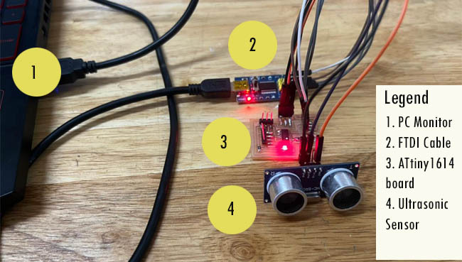
After programming, I removed the programmer and connected the FTDI connector to my PC and board to read serial data communication. The attachment is as follows:
The result is as shown below:
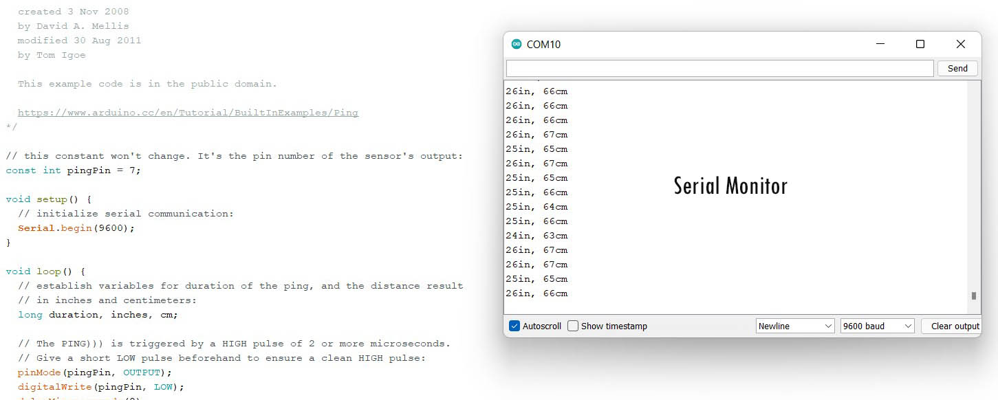
The result is as shown below:
LiDAR TF Luna
TF-Luna is a single-point ranging LiDAR, based on ToF principle. The Time-of-Flight principle (ToF) is a method for measuring the distance between a sensor and an object, based on the time difference between the emission of a signal and its return to the sensor, after being reflected by an object. LiDAR sensor is mainly used for stable, accuracy and high-frame rate range detection. The product is built with algorithms adapted to various application environments and adopts multiple adjustable configurations and parameters so as to offer excellent distance measurement performances in complex application fields and scenarios. You can find details about the sensor in this datasheet.
Major Electrical Parameters of TF-Luna is shown below:
| Description | Value Range |
|---|---|
| Power supply voltage | 3.7V-5.2V |
| Average current | ≤70mA |
| Peak current | 150mA |
| Power consumption | ≤350mW |
| Communication signal level | LVTTL (3.3V) |
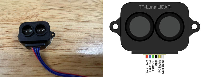
Pin Configurations
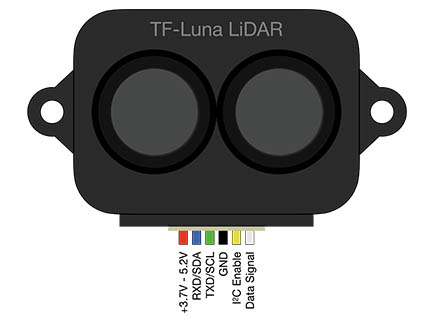
The TF-Luna LiDAR sensor has 6 pins:
1. VCC pin which requies 5V.
2. RXD/SDA pin which recieves data.
3. TXD/SCL pin which transmits ping.
4. GND pin ground
5. Configuration Input
6. Multiplexing Output
TF-Luna supports two interfaces: UART and I²C. This will be discussed in Networking & Communications week.
Programming TF Luna
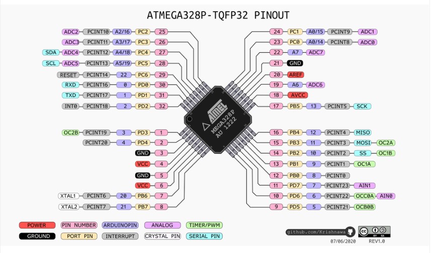
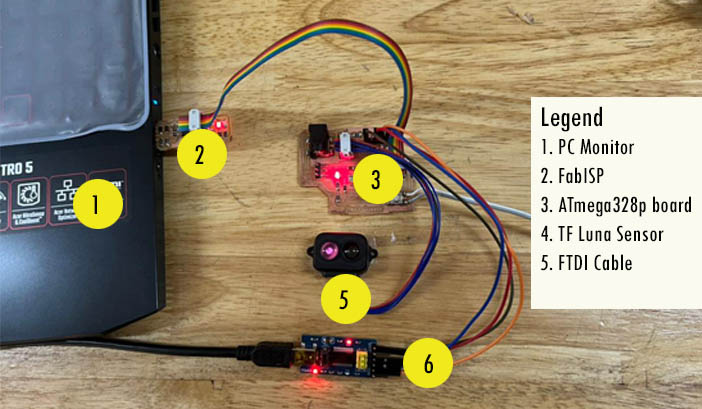
To program the sensor, I used my final project board which I designed with Atmega328p
microcontroller. You can find the pinout of Atmega328p for Arduino IDE in reddit.com
The following image shows the connections of my sensor to my board. I used USBtiny FabISP to program my board and FTDI cable to read the data in a serial monitor.
The program requires some changes in the Tools setting of Arduino IDE.
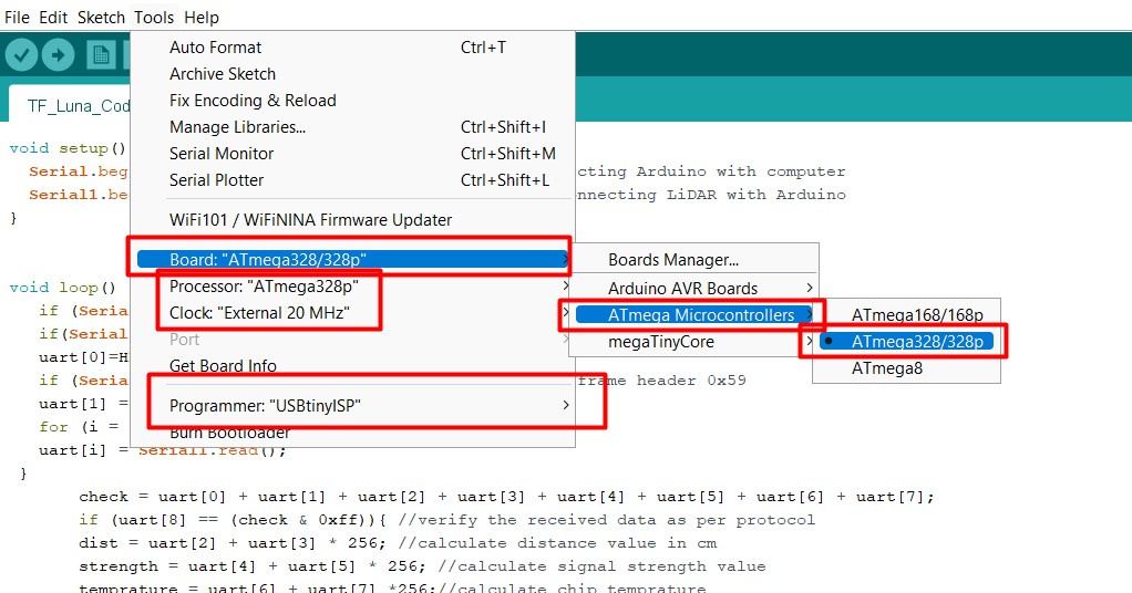
Details of setting boards for Atmega328p can be viewed in the documentation of Output week.
The sensor can read distance, signal strengths, temperature of the sensor. Following codes is used to program the sensor to get the data mentioned above. I have defined pin number 32 and 1 for Rx and Tx of the sensor.
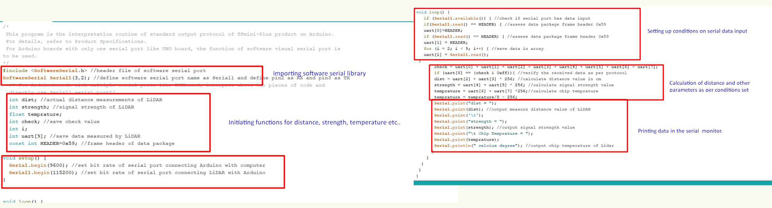
The original codes are seen below:
                                #include <SoftwareSerial.h> //header file of software serial port
                                SoftwareSerial Serial1(3,2); //define software serial port name as Serial1 and define pin2 as RX and pin3 as TX
                                  /* For Arduinoboards with multiple serial ports like DUEboard, interpret above two pieces of code and
                                  directly use Serial1 serial port*/
                                  int dist; //actual distance measurements of LiDAR
                                  int strength; //signal strength of LiDAR
                                  float temprature;
                                  int check; //save check value
                                  int i;
                                  int uart[9]; //save data measured by LiDAR
                                  const int HEADER=0x59; //frame header of data package

                                void setup() {
                                  Serial.begin(9600); //set bit rate of serial port connecting Arduino with computer
                                  Serial1.begin(115200); //set bit rate of serial port connecting LiDAR with Arduino
                                }


                                void loop() {
                                   if (Serial1.available()) { //check if serial port has data input
                                   if(Serial1.read() == HEADER) { //assess data package frame header 0x59
                                   uart[0]=HEADER;
                                   if (Serial1.read() == HEADER) { //assess data package frame header 0x59
                                   uart[1] = HEADER;
                                   for (i = 2; i < 9; i++) { //save data in array
                                   uart[i] = Serial1.read();
                                 }
                                       check = uart[0] + uart[1] + uart[2] + uart[3] + uart[4] + uart[5] + uart[6] + uart[7];
                                       if (uart[8] == (check & 0xff)){ //verify the received data as per protocol
                                       dist = uart[2] + uart[3] * 256; //calculate distance value in cm
                                       strength = uart[4] + uart[5] * 256; //calculate signal strength value
                                       temprature = uart[6] + uart[7] *256;//calculate chip temprature
                                       temprature = temprature/8 - 256;
                                       Serial.print("dist = ");
                                       Serial.print(dist); //output measure distance value of LiDAR
                                       Serial.print('\t');
                                       Serial.print("strength = ");
                                       Serial.print(strength); //output signal strength value
                                       Serial.print("\t Chip Temprature = ");
                                       Serial.print(temprature);
                                       Serial.println(" celcius degree"); //output chip temperature of Lidar
                                      }
                                    }
                                  }
                                 }
                                }
The result can be viewed below: Please noted the distance and other parameter changes in the serial monitor when I place my hands near the sensor and take it forward or near it.
Downloads
Download Eagle board file here
Download Eagle Schematic file here
Download the codes for Ultrasonic sensor here
Download the codes for TF Luna LiDAR sensor here