
Output Device
Group Assignment
Group Assignment:
measure the power consumption of an output device.
The group work that our group has done can be seen here
Individual Assignment:
add an output device to a microcontroller board you've designed, and program it to do something
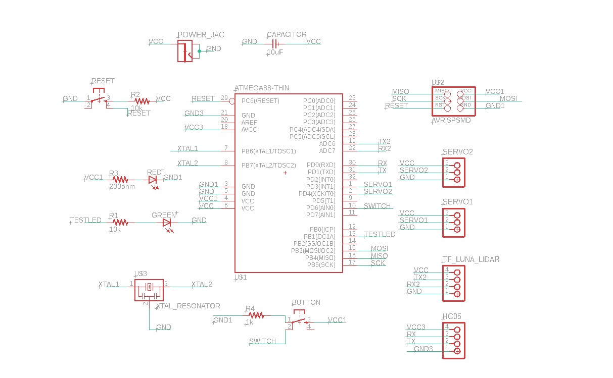
Microcontroller Board Design
It has been one heck of a week as I am trying to wrap up the assignments of the earlier weeks. Electronics is my weakness when it comes to fabacademy. I have little to zero knowledge on this matter. Therefore, it took me so many days to actually come up with an idea for my board. After several discussions with my instructors, I decieded to design my board with Atmega328p microcontroller so that I can also use the same board for my final project.
I referred Vijay Karale and also
I discussed with instructor Suhas for my board requirements. We listed out the following:
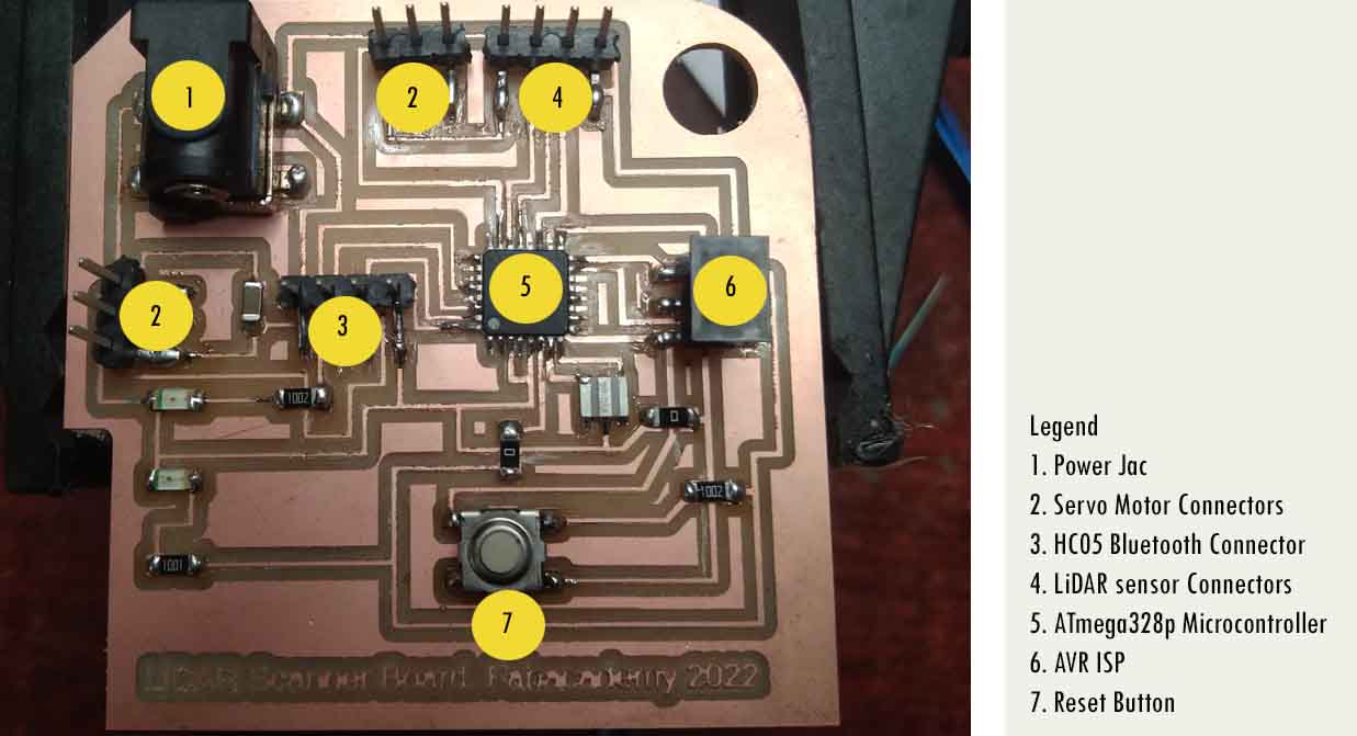
1. Microcontroller Atmega328p
2. Resonator 20 MHz
3. Reset switch
4. Power LED (RED)
5. AVR ISP
6. Power Jac to give external power to my board.
7. 4 pin connectors for hc05 bluetooth module
8. 4 pin connectors for LiDAR TF Luno
9. 2-3 pin header for my servo motors
10. LED Green for my tests
I started my board design in Eagle. I drew out an schematic diagram.
I tried to keep another button for my button so that I can use it to program, but it was very difficult to route, therefore, I removed it.
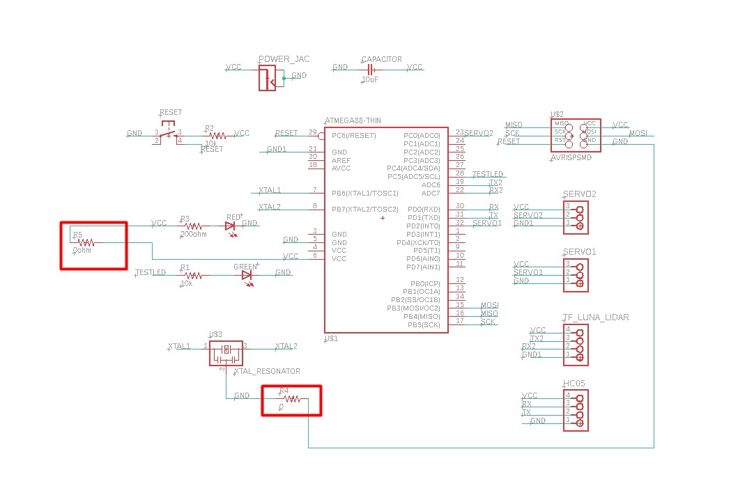
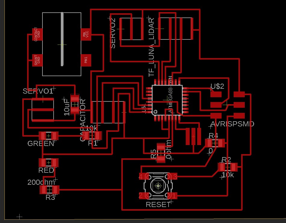
I also provided 2 zero ohm resistors so that, I can jump over some traces as it is very difficult to route. Finally, I was able to route my board. Before, routing:
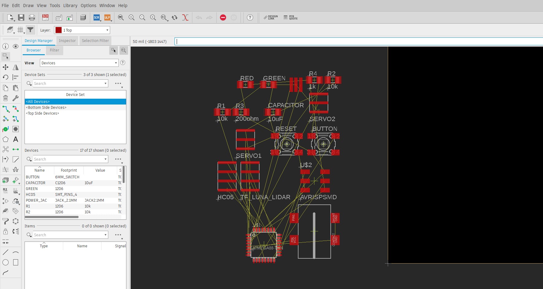
After final routing: I have to make sure that my power jac is protuding out so that I can install a power into that.
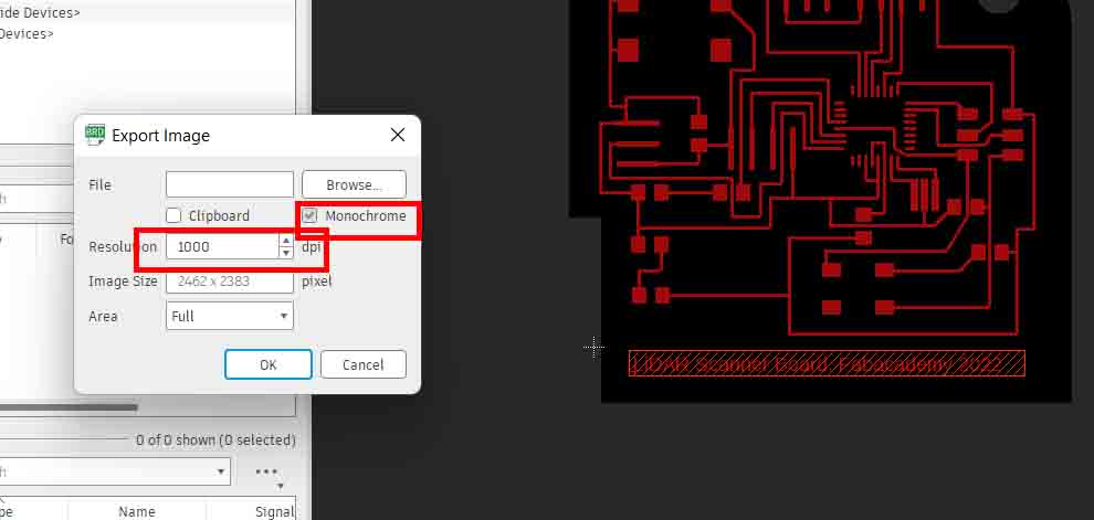
I exported my image files for trace after hiding all other layers.
Files ---> Export ---> Image ---> Make sure that you select Monochrome and make resolution atleast 1000 dpi. I exported in 300 dpi resolution
and the result is that you can't get a good trace in SRM-20 milling process.
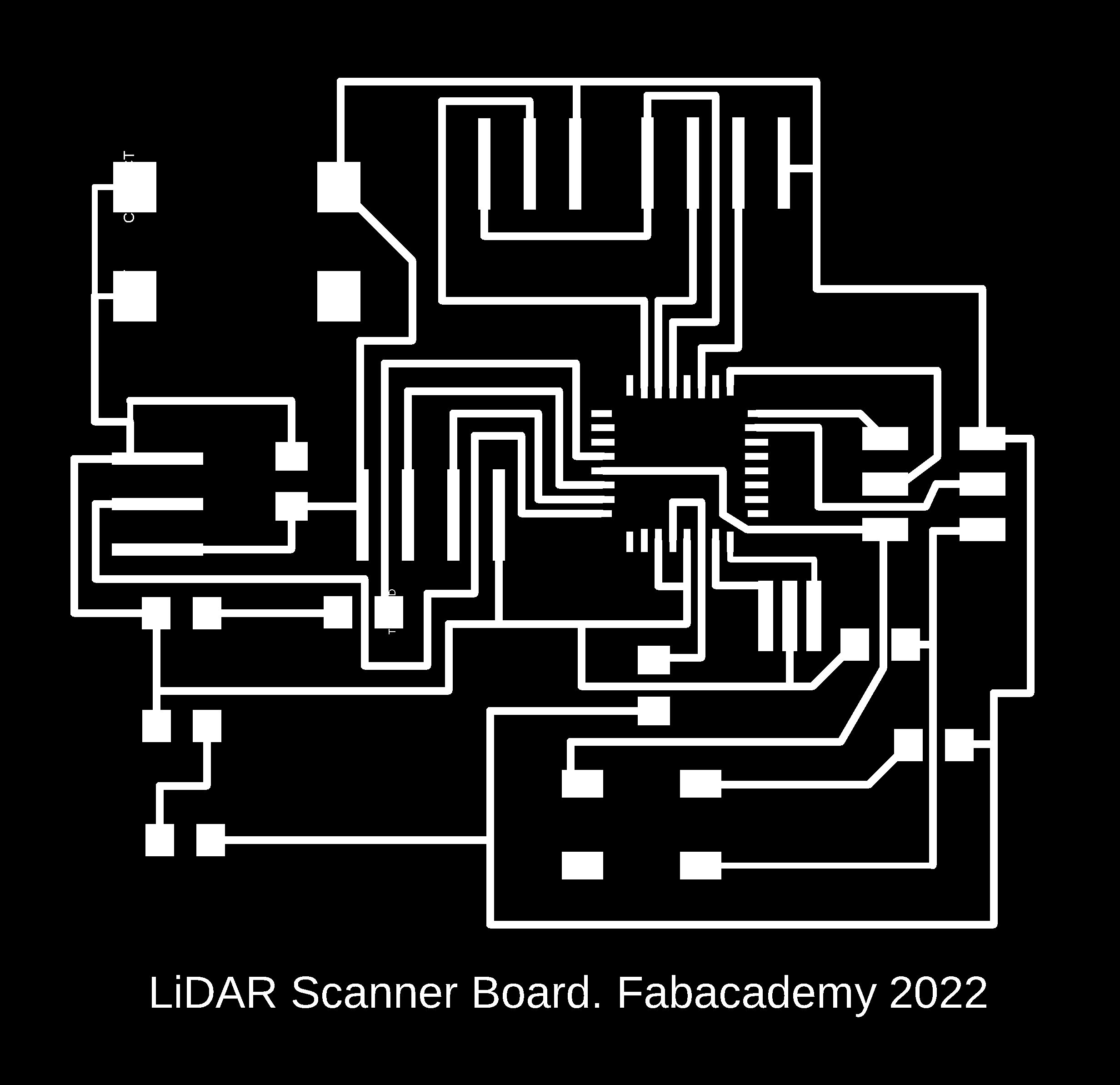
Download my trace file and my outline files.
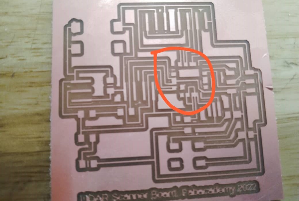
I milled my trace and outline in the SRM-20 machine but my resolution was only 300 dpi. Therefore, i couldn't get all the traces for Atmega328p microcontroller.
Therefore, I again exported my image and converted into rml file using MIT Mods Module. Follow the following tutorials:
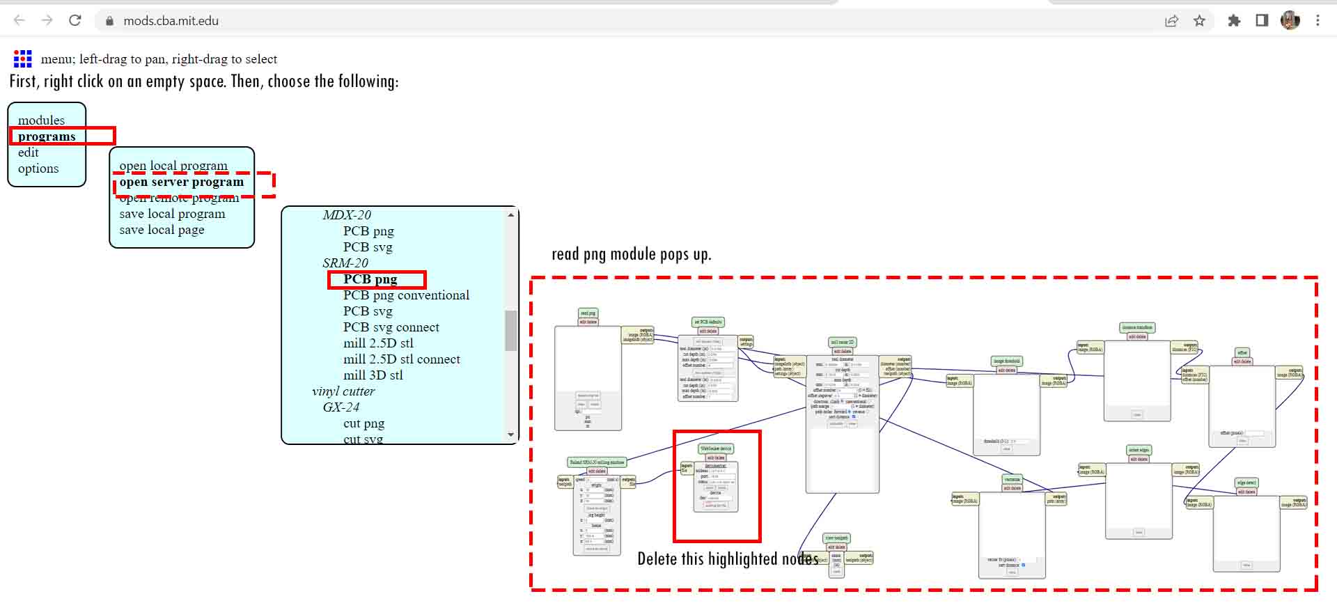
After, you import the server module to save the file and link it to the output files as shown below:
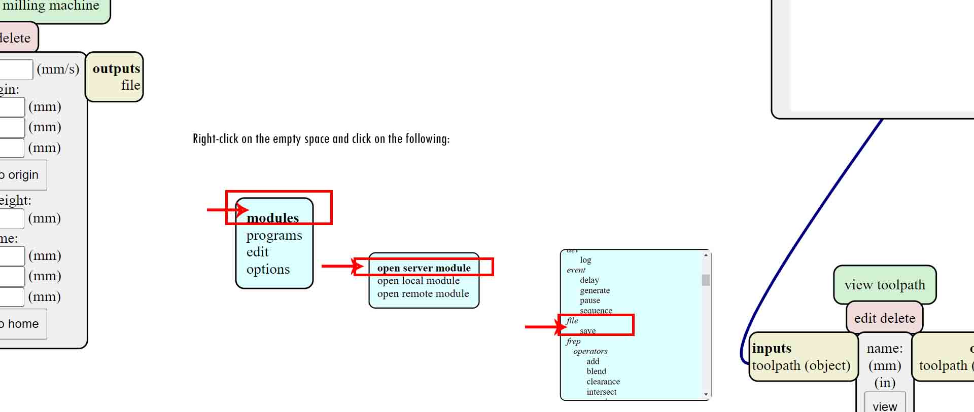
To create a .rml file, follow the following steps. Note: choose 1/64 end mill for traces and 1/32 end mill for outline.
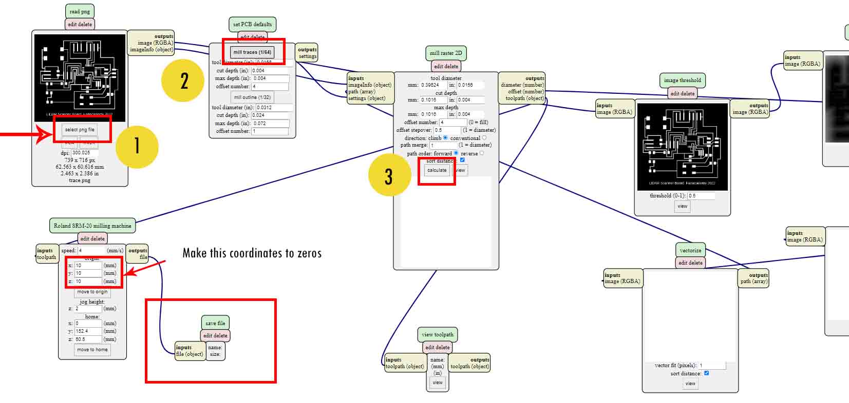
As I start milling again, our SRM-20 machine has been giving problems with an alignment as the zero on one point doesn't seem to be zero on another in z-axis. I had been attempting to align the base and mill it again and again.
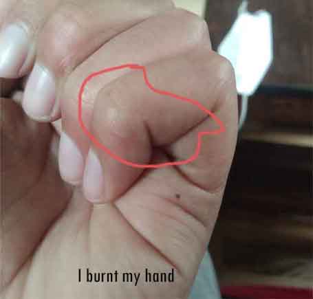
I soldered my board. I even burnt my finger as Atmega328p has a very tiny pins which are absolutely difficult to solder it.
However, I am determined to solder it.
After so many hours, I was able to solder it.
Video of me soldering my board.
Programing the Board
In order to check whether the board is rightly soldered, I used multimeter to test my connections, the connections are all okay.
After that, I used some previous student's page to refer how they programmed their board, I saw that they programmed using Arduino Nano board in arduino IDE, as it has Atmega328p microcontroller. But this does not work.
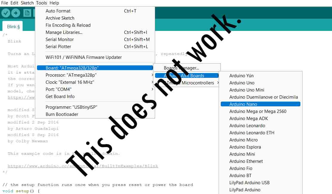
I realized this after so many failed trials. Even my instructor is not here, so it is quite difficult to interact with him. After suggestions from him, I looked in the google for solutions. As a test programming, my test LED should blink, before I put any output devices. As discussed earlier, my output device is a servo motors.
I saw a tutorial on how to get Atmega328p board here in github. I followed this tutorial.
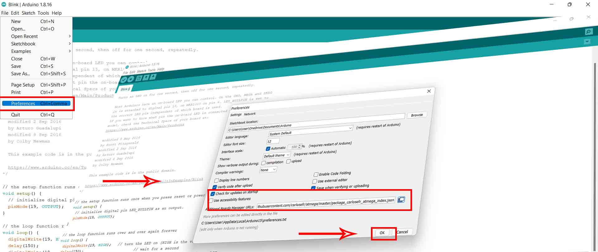
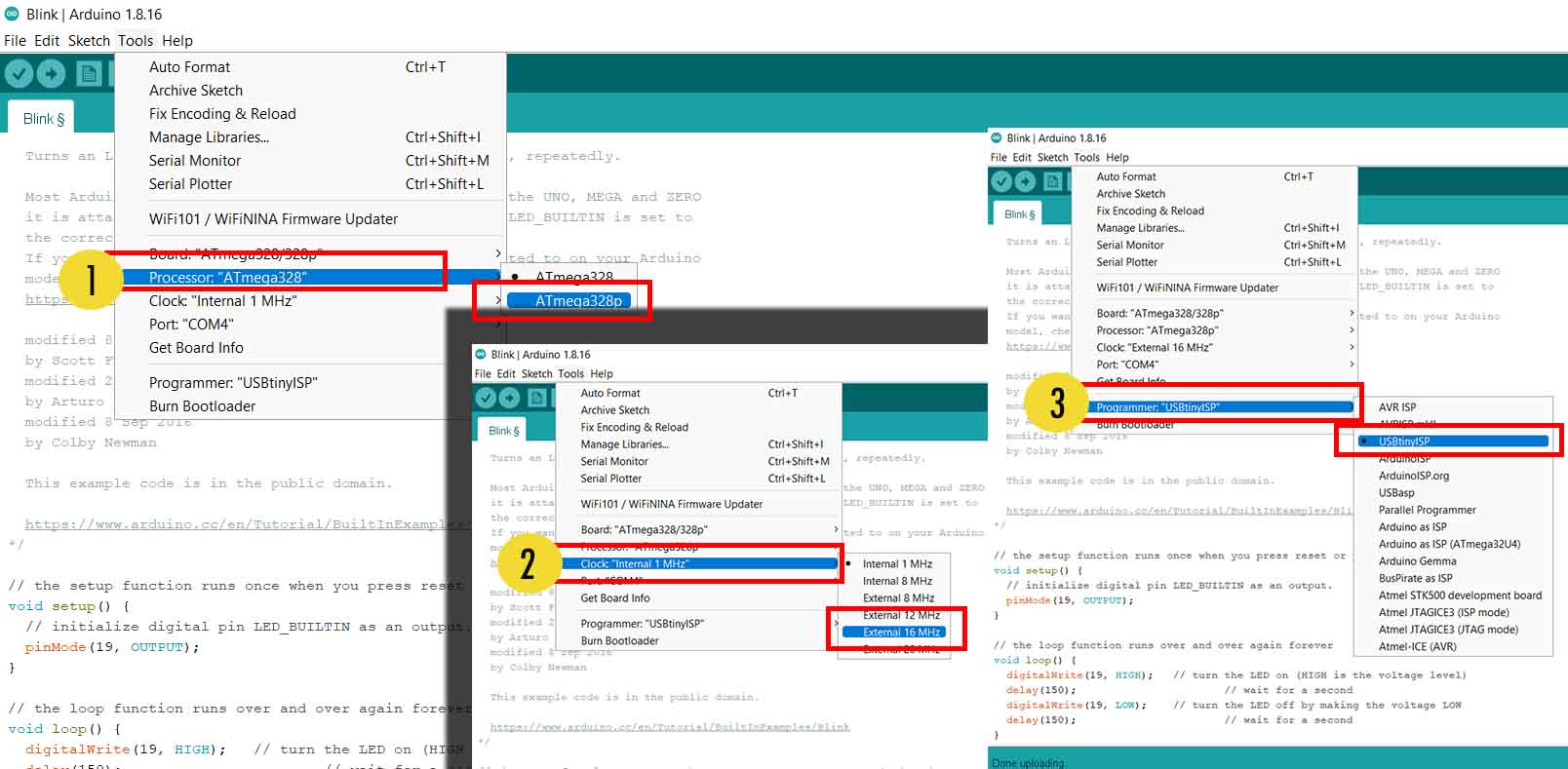
First Open Arduino IDE. ---> Got to Files ---> Preferences. Paste this url: https://raw.githubusercontent.com/carlosefr/atmega/master/package_carlosefr_atmega_index.json
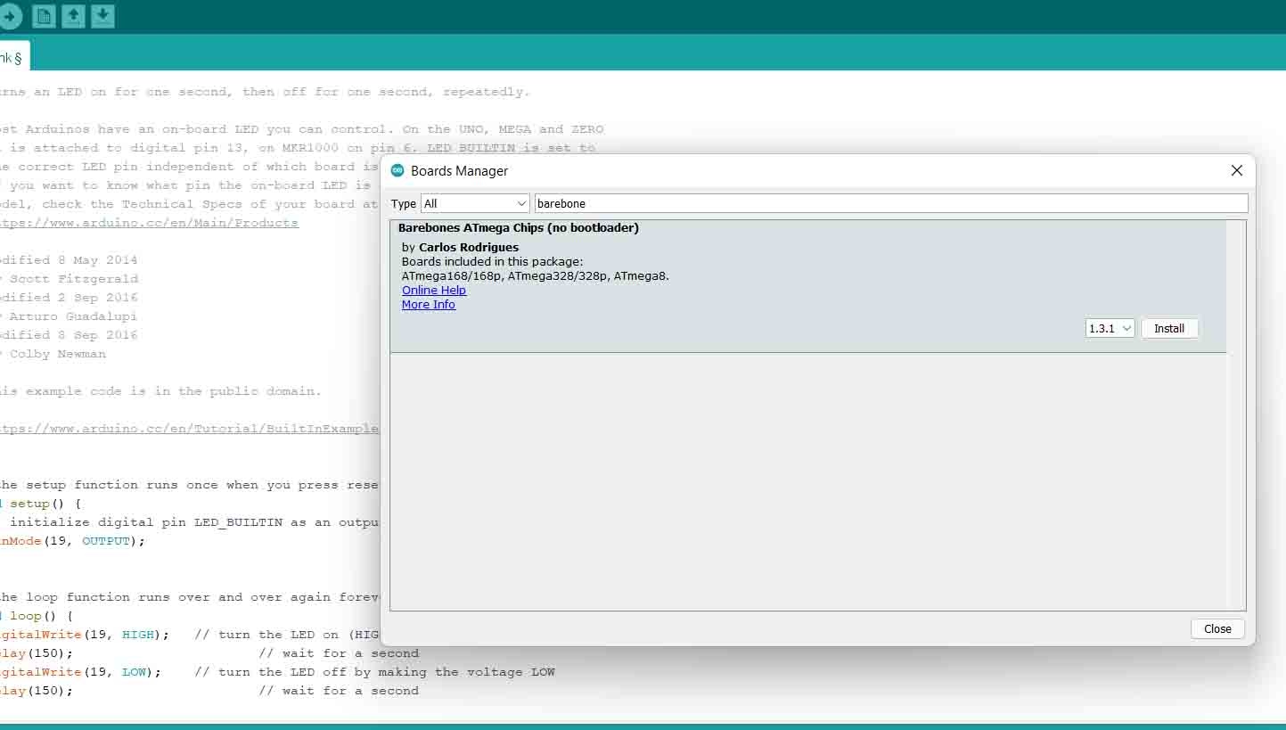
After that, Go to Tools ---> Board Manager ---> and search for Barebones ATmega Chips and install it.
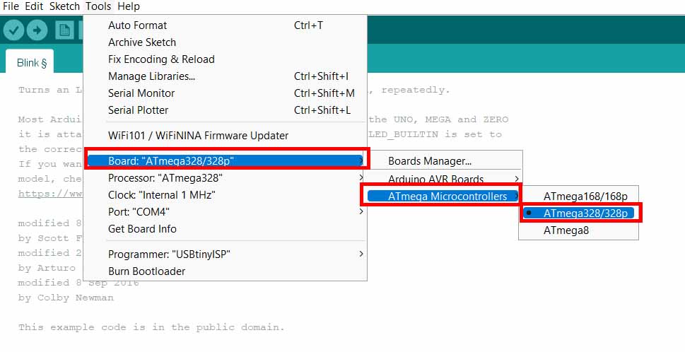
Now you can see anew section called ATmega Microcontrollers immediately appeared in the Tools > Board menu. Before starting the programming, few steps
are left as discussed in Embedded programming week. First, we need to set up the board.
Go to Tools --->Board ---> ATmega Microcontrollers -->
ATmega328/ATmega328p.
Select the processor as ATmega328p. --->Tools ---> Processor ---> ATmega328p
After that, Select the Clock as External 16 MHz. --->Tools ---> Clock ---> External 16MHz.
Select the Programmer as USBtinyISP. Tools ---> Programmer ---> USBtinyISP.
Finally, Burn Bootloader. Tools ---> Bootloader.
As a test for my board design, I programmed my Test LED I have soldered. Before that, I need to check out the ATmega328p Arduino Pinout diagram. I referred this website here. You can also refer the following diagram:
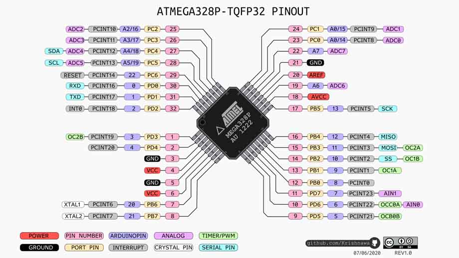
My LED is connected to Pin number 28 of the ATmega328p and corresponding pin in the arduio is A5/19. I programmed my LED using the following codes from the examples.
                                void setup() {
                                    // initialize digital pin LED_BUILTIN as an output.
                                    pinMode(19, OUTPUT);
                                  }

                                  // the loop function runs over and over again forever
                                  void loop() {
                                    digitalWrite(19, HIGH);   // turn the LED on (HIGH is the voltage level)
                                    delay(150);                       // wait for a second
                                    digitalWrite(19, LOW);    // turn the LED off by making the voltage LOW
                                    delay(150);                       // wait for a second
                                  }
You can see the result as seen below, it also means that my board and programming steps are correct for now.
Servo Motor as an Output Device
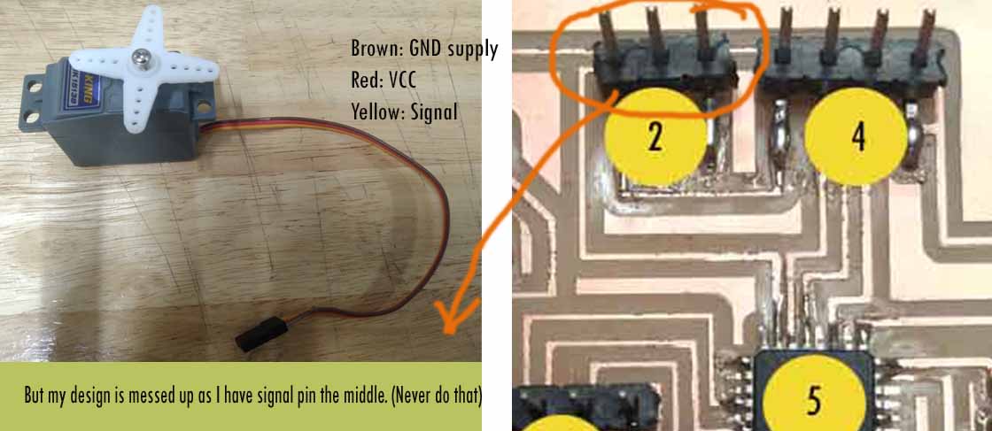
I have HobbyKing™ HK15138 Standard Analog Servo 4.3kg / 0.17sec / 38g as my output device for my final project. It has requriements of 3 pins i.e., GND, VCC and one signal pin. However, I overlooked during my design and I have mistaken the orders of the pins during my design of the board. I need to be careful next time and check the connections before I finish my design.
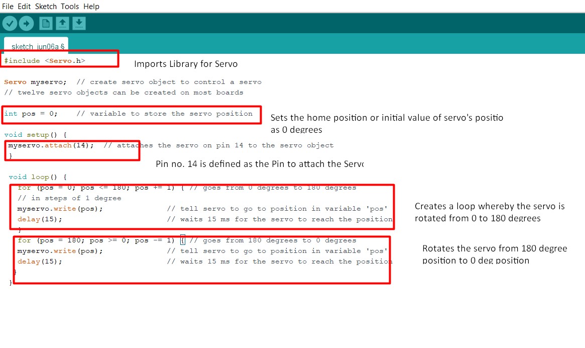
I used the example files from the Arduino IDE, however, the pin I used for the servo pin is 23 which is pin no. 14 in arduino IDE, therefore, I used pin 14 in my porgramming.
                                #include

                                    Servo myservo;  // create servo object to control a servo
                                    // twelve servo objects can be created on most boards

                                    int pos = 0;    // variable to store the servo position

                                    void setup() {
                                      myservo.attach(14);  // attaches the servo on pin 14 to the servo object
                                    }

                                    void loop() {
                                      for (pos = 0; pos <= 180; pos += 1) { // goes from 0 degrees to 180 degrees
                                        // in steps of 1 degree
                                        myservo.write(pos);              // tell servo to go to position in variable 'pos'
                                        delay(15);                       // waits 15 ms for the servo to reach the position
                                      }
                                      for (pos = 180; pos >= 0; pos -= 1) { // goes from 180 degrees to 0 degrees
                                        myservo.write(pos);              // tell servo to go to position in variable 'pos'
                                        delay(15);                       // waits 15 ms for the servo to reach the position
                                      }
                                    }
The codes are explained as below:
The result is as seen below:
Design Files
Download Eagle board file here
Download Eagle Schematic file here
DC Motor as an Output Device
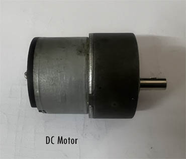
In order to familiarize myself with the DC Motor, I referred DC Motors. A direct current (DC) motor is a type of machine that converts electrical energy into mechanical energy. DC motors take electrical power through direct current, and convert this energy into mechanical rotation. Controlling DC motor is with Arduino or any microcontroller board is quite complicated due to several reasons:
Therefore, DC Motors require a bridge between a Microcontroller Board and and the DC Motor called L298N H-Bridge or simply called Motor Driver.
Working Principle of DC Motor
The working Principle of DC is motor is based on the principle that when a current carrying conductor is placed in a magnetic field, it experiences a machanical force. For the detail of working principle, please refer the aforementioned link.
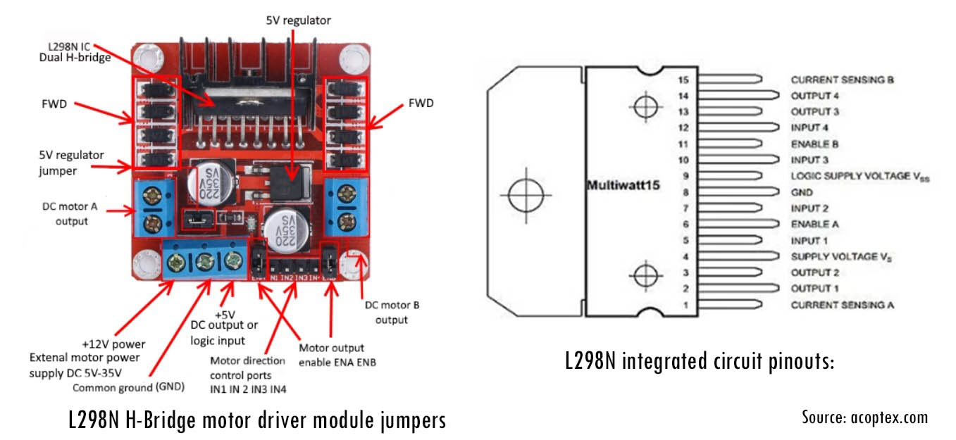
L298N DC Motor Driver Module
According to LastMinuteEngineers, In order to have a complete control over DC motor, we have to control its speed and rotation direction. This can be achieved by combining these two techniques.
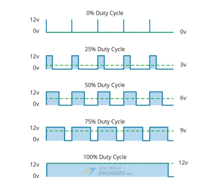
PWM or Pulse Width Modulation is the method of controlling the speed of a DC motor by varying its input voltage. PWM is a technique where average value of the input voltage is adjusted by sending a series of ON-OFF pulses.
The average voltage is proportional to the width of the pulses known as Duty Cycle. The higher the duty cycle, the greater the average voltage being applied to the dc motor(High Speed) and the lower the duty cycle, the less the average voltage being applied to the dc motor(Low Speed). The image from the website attached best describes it:
H-Bridge is a common technique used to control the DC motor’s spinning direction by changing polarity of its input voltage. An H-Bridge circuit contains four switches with the motor at the center forming an H-like arrangement. The details of pins and pinout can be seen in the image attached below:
Wiring H-Bridge with a Board
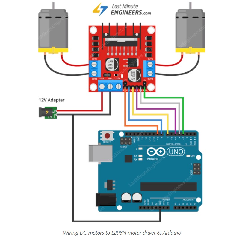
Keeping Arduino Uno as an example board, the tutorials to connections can be seen here.
First, I am going start by giving a power supply. The DC motor I am using are rated for 12V, therefore, we will connect external 12V power supply to the VCC terminal.
Considering internal voltage drop of L298N IC, the motors will receive 10V and will spin at slightly lower RPM.
Next, I need to supply 5 Volts for the L298N’s logic circuitry. I am going to supply 5V from my board.
Now, the input and enable pins(ENA, IN1, IN2, IN3, IN4 and ENB) of the L298N module are connected to six Arduino digital output pins(9, 8, 7, 5, 4 and 3). Note that the Arduino output pins 9 and 3 are both PWM-enabled.
Finally, connect one motor to terminal A(OUT1 & OUT2) and the other motor to terminal B(OUT3 & OUT4). You can interchange your motor’s connections, technically, there is no right or wrong way.
For my Custom Design Board whereby, I am using the Atmega328p board which I have designed for my final project, I am using my output pins to supply 5V and to provide signal pins to program DC Motor. For my signal pin, I am giving pin number 2 in Atmega328p board which is Pin no. 4 in Arduino IDE.
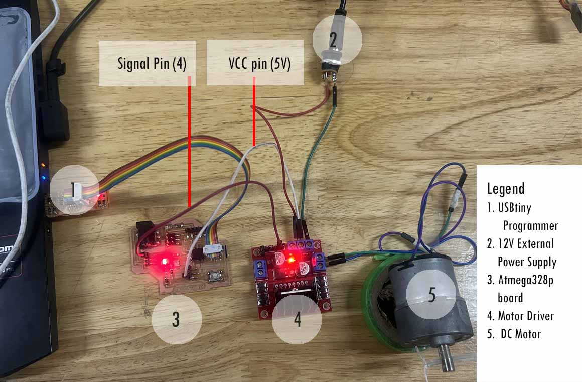
Programming DC Motor
In order to program DC Motor with Motor Driver, I need to use one signal pin which I am giving Pin no 2 which is pin no 4 in Arduino IDE. The code is explained as shown below:
Codes for referrence is shown below:
/*
* Created by ArduinoGetStarted.com
*
* This example code is in the public domain
*
* Tutorial page: https://arduinogetstarted.com/tutorials/arduino-dc-motor
*/
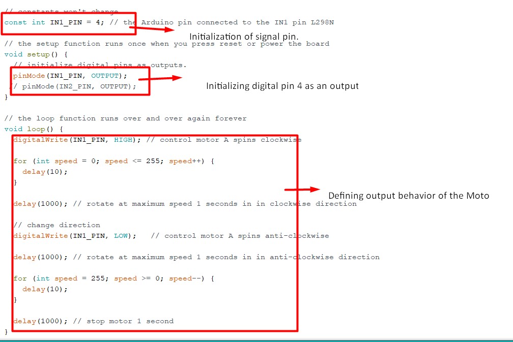
// constants won't change
const int IN1_PIN = 4; // the Arduino pin connected to the IN1 pin L298N
// the setup function runs once when you press reset or power the board
void setup() {
// initialize digital pins as outputs.
pinMode(IN1_PIN, OUTPUT);
// pinMode(IN2_PIN, OUTPUT);
}
// the loop function runs over and over again forever
void loop() {
digitalWrite(IN1_PIN, HIGH); // control motor A spins clockwise
for (int speed = 0; speed <= 255; speed++) {
delay(10);
}
delay(1000); // rotate at maximum speed 1 seconds in in clockwise direction
// change direction
digitalWrite(IN1_PIN, LOW); // control motor A spins anti-clockwise
delay(1000); // rotate at maximum speed 1 seconds in in anti-clockwise direction
for (int speed = 255; speed >= 0; speed--) {
delay(10);
}
delay(1000); // stop motor 1 second
}
The following video demonstrates the above experiment with the Arduino codes:
Download the Arduino codes here here