Embedded programming is a specific type of programming that supports the creation of consumer facing
or business facing devices that don't operate on traditional operating systems the way that
full-scale laptop computers and mobile devices do.
CHECK LIST
Group assignment
Compare the performance and development workflows for other architectures
Individual assignments
Read a microcontroller data sheet
Program your board to do something, with as many different programming languages
and programming environments as possible
Link to the group assignment page
Document what you learned from reading a microcontroller datasheet.
Program your board
Describe the programming process/es you used
Include your source code
Include a short ‘hero video’ of your board
GROUP ASSIGNMENT
Find out the details of our common work al ZOI
Here.
BASIC CONCEPTS
There are some basic concepts I had to look for further infomation in order to understand this
week assignment. It is pretty challenging to get all of this as I am completely new in this field.
Microprocessor (Raspberry pi): is the central unit of a computer system that performs arithmetic and logic operations,
which generally include adding, subtracting, transferring numbers from one area to another, and comparing two
numbers. It's often known simply as a processor, a central processing unit, or as a logic chip.
It's essentially the engine or the brain of the computer that goes into motion when the computer is switched on.
It's a programmable, multipurpose device that incorporates the functions of a CPU (central processing unit)
on a single IC (integrated circuit).
A microprocessor accepts binary data as input, processes that data, and then provides output based on the
instructions stored in the memory. The data is processed using the microprocessor's ALU (arithmetical and
logical unit), control unit, and a register array. The register array processes the data via a number of
registers that act as temporary fast access memory locations. The flow of instructions and data through the
system is managed by the control unit. Here, more information about microcontrollers and microprocessors..
Microcontrollers (Arduino): are tiny computers, and if used in conjunction with analog circuitry, can give that
circuitry a more advanced behavior. They can also be reprogrammed to perform different functions as needed.
The microcontroller is the brains of a system, but it needs data to either sense things about or affect things
in its environment. It uses inputs and outputs to do so. Inputs: They tell it what is going on in the world. At its most basic, an input could be a switch,
such as a light switch in your home. At the other end of the spectrum, it could be a gyroscope. Outputs: allow your Arduino to affect the real world in some way. An output could be very subtle and
discreet, such as in the same way that a mobile phone vibrates, or it could be a huge visual display on the
side of a building that can be seen for miles around.
Microcontrollers are designed to interpret and process data and instructions
in binary form. Patterns of 1's and 0's make up the machine language of microcontrollers, and it is the
only thing they are capable of understanding. These 1's and 0's represent the minimum unit of information,
known as a bit, since it can only adopt one of two possible values: 0 or 1.
Programming is commonly carried out in a high-level language, that is, a language that uses phrases or words
similar to or typical of human language. High-level language sentences greatly facilitate programming since
they are familiar to the way we communicate. Languages like C or BASIC are commonly used in microcontroller
programming.
All programs written in a high-level language must be transformed into machine code. The programs we write
are understood by us, not by the microcontroller.
Computer software, called a compiler, translates and transforms our program into machine code,
which is what the microcontroller can actually read and interpret. Once the program is compiled, it is
time to transfer our machine code to the internal memory of the microcontroller, usually to the ROM.
For this task a physical programmer is used, which is a piece of hardware that has the purpose of writing
the program in the internal memory of the micro. Further information..
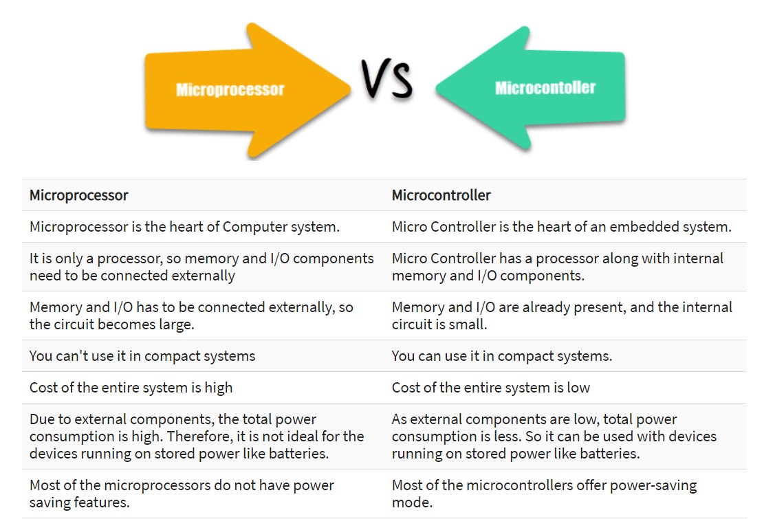
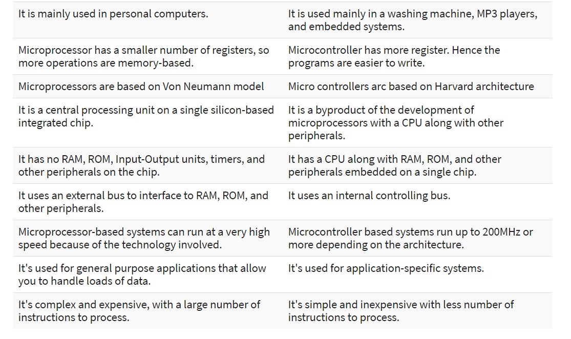
The following table shows some important differences between a microprocessor and microcontroller:
I got this information from Guru99 you can check it for more details,
it helped me a lot to understand this concepts.
Common Terms Used
Word length: refers to the number of bits in the processor's internal data bus--or the number
of bits that a processor can process at any given time. For example, an 8-bit processor will have
8-bit registers, an 8-bit data bus, and will perform 8-bit processing at a time.
Instruction set: is the series of commands that a microprocessor can understand. Essentially,
it's the interface between the hardware and the software.
Cache memory: is used to store data or instructions that the software or program
frequently references during operation. Basically, it helps to increase the operation's overall
speed by allowing the processor to access data more quickly than from a regular RAM.
Clock speed: is the speed at which a microprocessor is able to execute instructions.
It's typically measured in Hertz and expressed in measurements like MHz (megahertz) and GHz (gigahertz).
Bus: is the term used to describe the set of conductors that transmit data or that address or
control information to the microprocessor's different elements. Most microprocessors consist of three
different buses, which include the data bus, the address bus, and the control bus.
AVR: is a family of microcontrollers developed since 1996 by Atmel, acquired by Microchip Technology
in 2016. These are modified Harvard architecture 8-bit RISC single-chip microcontrollers.
AVR was one of the first microcontroller families to use on-chip flash memory for program storage,
as opposed to one-time programmable ROM, EPROM, or EEPROM used by other microcontrollers at the time.
Memory: A microcontroller typically has 3 types of memory: Flash, RAM, and EEPROM.
Flash is a type of nonvolatile memory; that is, it's a memory that keeps the information
transferred to it even when the power to the microcontroller is shut off. RAM is the memory
for temporary storage, such as when the program is being actively executed. EEPROM,
like Flash, is nonvolatile. However, it is slower and there is less of it, so more often than not,
the Flash memory is the more used and important of the 2 nonvolatile memories.
Static Random Access Memory (SRAM): is a type of volatile semiconductor memory to store binary
logic '1' and '0' bits. SRAM uses bistable latching circuitry made of Transistors/MOSFETS to store each
bit. Compared to Dynamic RAM (DRAM), SRAM does't have a capacitor to store the data, hence SRAM works
without refreshing. In SRAM the data is lost when the memory is not electrically powered.
Analog circuit: is a circuit with a continuous, variable signal (that is, an analog signal),
as opposed to a digital circuit where a signal must be one of two discrete levels. Analog circuits
within electrical equipment can convey information through changes in the current, voltage, or frequency.
Most electronics today use digital circuits because they are easier to design and less susceptible to
noise, among other benefits. However, a device that interfaces with the environment requires at least
some analog component to take in this information before converting the signal to digital
(using what is known as an analog-to-digital converter). Here, an interesting explanation about analog circuits..
This information was taken from BRAINSPIRE.
I leave it here for quick consult.
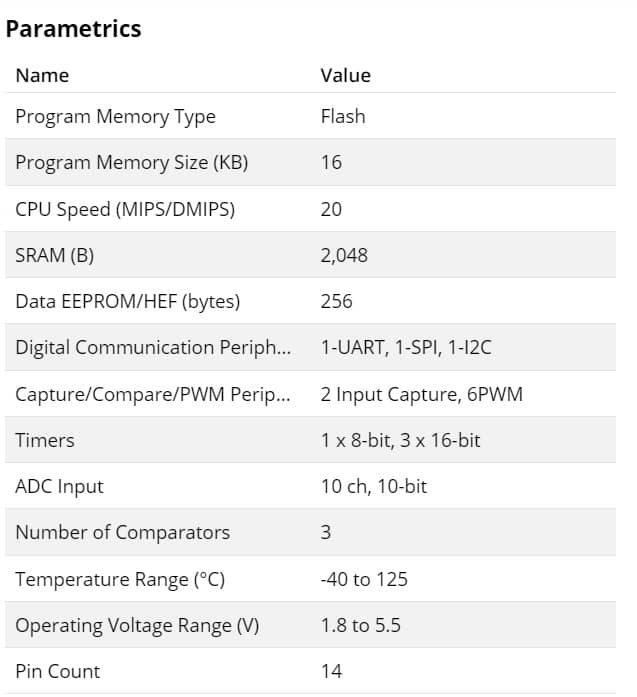
The ATtiny1614 is a microcontroller featuring the 8-bit AVR® processor with hardware multiplier,
running at up to 20 MHz and with 16 KB Flash, 2 KB SRAM and 128B of EEPROM in a 14-pin package.
The series uses the latest Core Independent Peripherals with low-power features, including Event System,
intelligent analog and advanced peripherals. The integrated QTouch® peripheral touch controller supports
capacitive touch interfaces with proximity sensing and a driven shield.
Features
tinyAVR microcontrollers are equipped with high-speed integrated analog, hardwarebased Core Independent Peripherals
(CIPs) and low-power performance for efficient, real-time control and sensor node applications in a small
physical footprint to help optimize board layout. This family offers a broad range of memory and
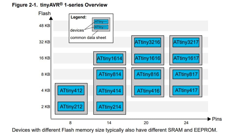
pin-andpackage configurations, from 2 KB to 32 KB Flash memory and 8- to 24-pin packages.
The tinyAVR microcontrollers are well-suited for a wide range of applications including
industrial, consumer, appliances, automotive and Internet of Things (IoT) sensor nodes.
microcontroller. More info about tiny microcontrollers.
The following diagram shows flash memory size of different components from this family:
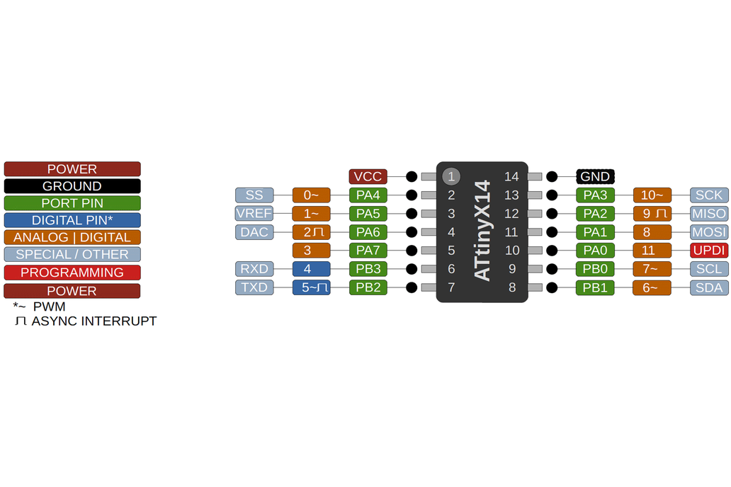
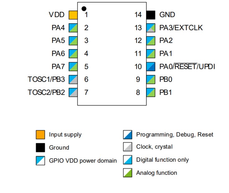
It is important to be aware of the function of each pin.
VDD: Supply voltage.
GND: Ground.
Digital pins: Port A: PA0, PA1, PA2, PA3, PA4, PA5, PA6, PA7. Port B: PB0, PB1, PB2, PB3, PB4, PB5. Port C: PC0, PC1, PC2, PC3.
Analog pins: Port A: PA0, PA1, PA2, PA3, PA4, PA5, PA6, PA7. Port B: PB0, PB1, PB4, PB5.
UPDI Programming pin: PA0 (physical pin number 16).
What I learned from reading the microcontroller data sheet
Now I realize how important is to read the data sheet, not only of the microcontrollers but pretty much of everything we use. It gives a lot of information
on how to use the components, its characteristics, capabilities, and others. Dependign of our needs of design it helps us to choose the best component and
take out the best of it, also to know its limitations.
It is important yo keep in mind which kind of input component you are using, digital or analog:
for example, for an analog component like a temperature sensor (analog component) you have to connect
it to an analog to digital converter (ACD) port, otherwise the microcontroller isn't able to transform
the information that is receiving from the sensor to a digital data.
According to the web site there are two ways to install the megaTinyCore on the Arduino IDE:
Installation via the Arduino Board Manager
Manual Installation
I chose the first option, and followed these steps:
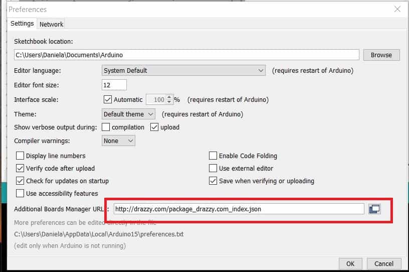
Open the preferences window from the Arduino IDE. Go to File > Preferences or Arduino > Preferences
On the preferences window, locate the “Additional Board Manager URLs” text box and enter http://drazzy.com/package_drazzy.com_index.json into the field as shown below and click the OK button
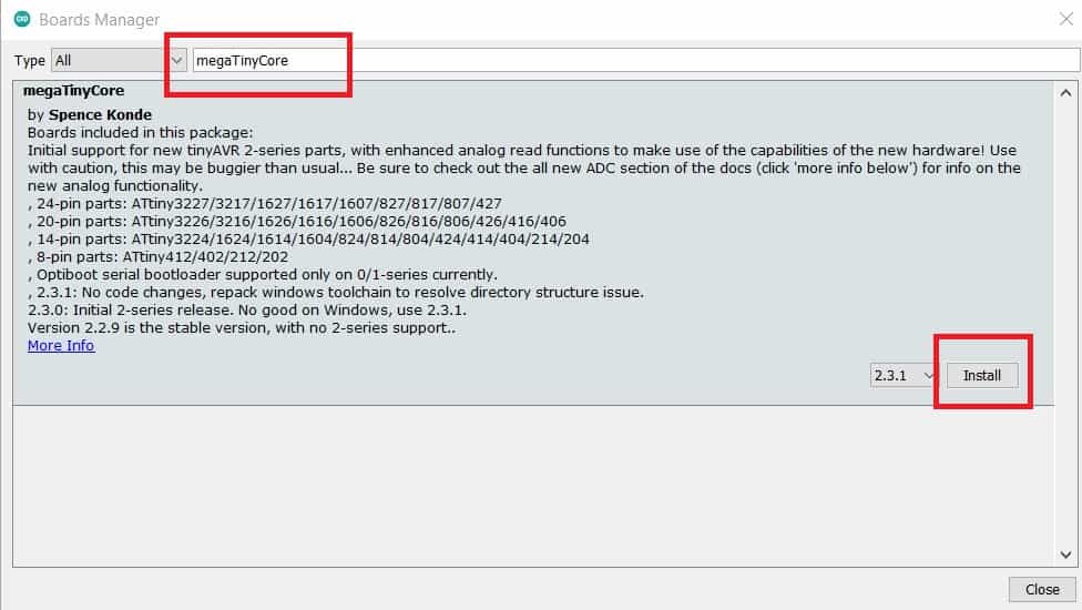
Open the Arduino board manager. Go to tools>Boards>Boards manager
When the board manager opens up, enter megaTinyCore into the search bar and scroll, you will see “megaTinyCore by Spence Konde”, click on install as shown below.
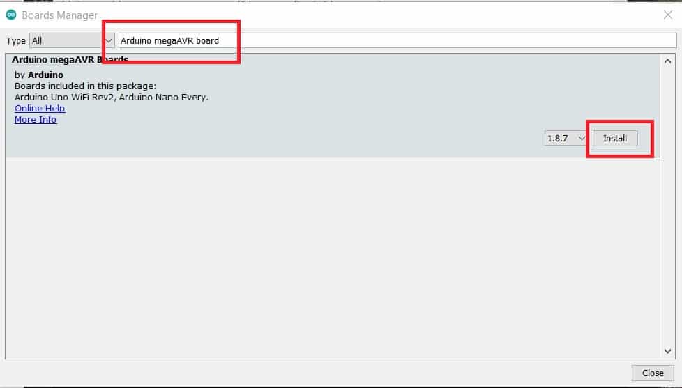
Also, search for the “Official Arduino megaAVR boards” package by Arduino and install the most recent version of that too
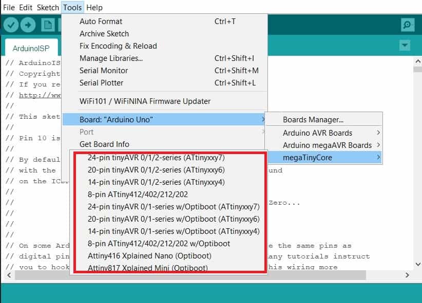
Now the Attiny boards are avaliable under the Boards section Tools>Boards of the Arduino IDE, this means the board installation was successful.
MAKE THE UPDI PROGRAMMER
In order to upload a code to the attiny, is needed to make a UPDI programmer and for this I am going to use an Arduino board and arduino IDE.
First, I have to transform the Arduino board to work as a UPD programmer. Then, I have to connect the attiny to the programmer to upload the code.
1. Transform the arduino to a UPDI programmer
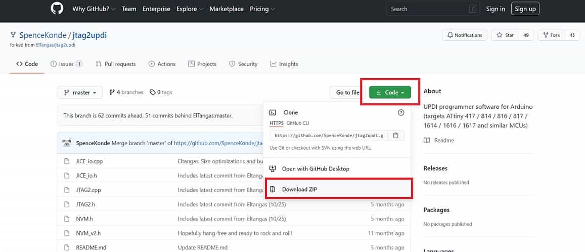
For this is necessary to use the UPDI Arduino sketch created by
ElTangas
The sketch converts ATmega328(p)-based Arduino’s, like the Arduino UNO, Nano, and Pro mini, into a UPDI programmer.
These are the steps to make the UPDI programmer:
Close all instances of the Arduino IDE to avoid errors.
Open the jtag2updi folder after extracting the download
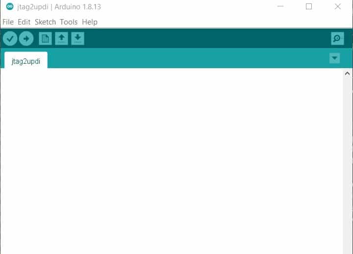
Open the sketch jtag2updi.ino and upload it to the Arduino board you will like to use which for this case is an Arduino UNO.
When you open the code, the .ino file will appear empty and that is fine as all the code is contained in the other files in the same folder as the .ino, but the empty .ino is needed so they can be compiled by the IDE.
With the upload successful, now the UPDI programmer is ready to use.
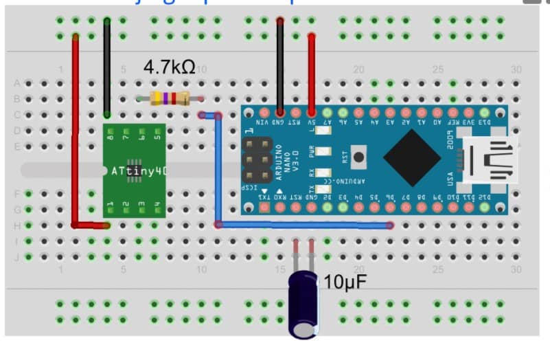
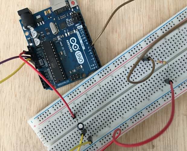
2. Connecting th Attiny and uploading
Connect the ATiny to the Arduino as shown in the schematics below;
To prevent mistakes the following chart shows the pin to pin connection between the Arduino and the Attiny:
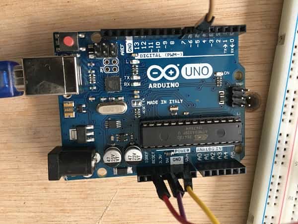
Arduino
Attiny
GND
GND
5V
VCC
D6
UPDI
Also add:
4.7Ω resistance
10uf capacitor
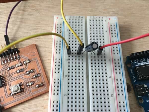
3.Upload the code
Follow the next steps:
Connect the board to the Arduino
Paste the code. For this a used Adrian's example, avaliable here:
//Adrián Torres - Fab Academy 2020 - Fab Lab León
//tiny1614 hello_train
//
//Original code:Neil Gershenfeld 12/8/19
// This work may be reproduced, modified, distributed,
// performed, and displayed for any purpose, but must
// acknowledge this project. Copyright is retained and
// must be preserved. The work is provided as is; no
// warranty is provided, and users accept all liability.
//
const int ledPin1 = 3;//first light
const int ledPin2 = 6;//white light
const int ledPin3 = 7;//white light
const int ledPin4 = 1;//red light
const int ledPin5 = 2;//red light
const int buttonPin = 0;// button pin
int buttonState = 0;//initial state of the button
int i = 0; //variable intensity led

void setup() { //declaration of inputs and outputs
pinMode(ledPin1, OUTPUT);
pinMode(ledPin2, OUTPUT);
pinMode(ledPin3, OUTPUT);
pinMode(ledPin4, OUTPUT);
pinMode(ledPin5, OUTPUT);
pinMode(buttonPin, INPUT);
}
void loop() {
buttonState = digitalRead(buttonPin);// we read the state of the button
if (buttonState == HIGH) { //if we press the button
digitalWrite(ledPin2, HIGH);
digitalWrite(ledPin3, HIGH);
delay(2000);
digitalWrite(ledPin4, HIGH);
digitalWrite(ledPin5, HIGH);
delay(2000);
digitalWrite(ledPin1, HIGH);
delay(5000);

}
else {  //if we don't press the button
digitalWrite(ledPin1, LOW);
digitalWrite(ledPin2, LOW);
digitalWrite(ledPin3, LOW);
digitalWrite(ledPin4, LOW);
digitalWrite(ledPin5, LOW);
}
}
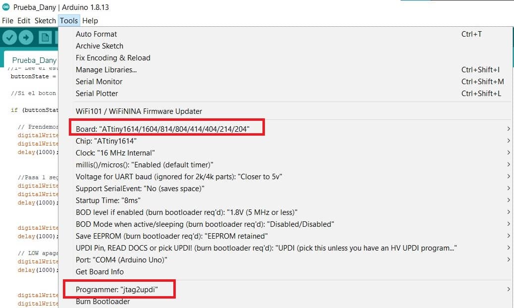
To verify that there is no error, you can go to Tools>Board>and scroll down to see the ATtiny you are working with
on the list and select it.In this case the ATtiny1614
Tell the Arduino to use our programmer. Go to Tools>Programmers>jtag2updi
Click on upload on the IDE and the board should work as programmed.
Based on Adrian's work I made some changes on the code, this is the result:
//Daniela Felix - Fab Academy 2021 - Fab Lab ZOI
//tiny1614
//
//Original code:Neil Gershenfeld 12/8/19
// This work may be reproduced, modified, distributed,
// performed, and displayed for any purpose, but must
// acknowledge this project. Copyright is retained and
// must be preserved. The work is provided as is; no
// warranty is provided, and users accept all liability.
//
const int ledPin1 = 3;//blue led
const int ledPin2 = 6;//red led
const int ledPin3 = 7;//red led
const int ledPin4 = 1;//blue led
const int ledPin5 = 2;//blue led
const int buttonPin = 0;// reset button
int buttonState = 0;//initial state of the button
int i = 0; //variable intensity led

void setup() { //declaration of inputs and outputs
pinMode(ledPin1, OUTPUT);
pinMode(ledPin2, OUTPUT);
pinMode(ledPin3, OUTPUT);
pinMode(ledPin4, OUTPUT);
pinMode(ledPin5, OUTPUT);
pinMode(buttonPin, INPUT);
}
void loop() {
buttonState = digitalRead(buttonPin);// we read the state of the button
if (buttonState == HIGH) { //if we press the button
digitalWrite(ledPin2, HIGH);
digitalWrite(ledPin3, HIGH);
delay(1000);
digitalWrite(ledPin4, HIGH);
digitalWrite(ledPin5, HIGH);
delay(1000);
digitalWrite(ledPin1, HIGH);
delay(1000);
digitalWrite(ledPin1, LOW);
delay(1000);
digitalWrite(ledPin4, LOW);
digitalWrite(ledPin5, LOW);
delay(1000);
digitalWrite(ledPin2, LOW);
digitalWrite(ledPin3, LOW);
delay(1000);

}
else {  //if we don't press the button
digitalWrite(ledPin1, LOW);
digitalWrite(ledPin2, LOW);
digitalWrite(ledPin3, LOW);
digitalWrite(ledPin4, LOW);
digitalWrite(ledPin5, LOW);
}
}
Why I chose Arduine IDE to program
Arduino has been a useful tool to help me understand basic concepts and applications. So far is the only program I know and understand how to use, upload the code,
and so on. It is intuiutive and there is a lot of seto by step information online which has been really helpful.
SOME THOUGHTS ABOUT THIS WEEK
This was a challenging week, for me, it takes a lot of time to understand the basic concepts and how they work
together. It is a new way of learning and undersanding, first trying and exploring, then searching and apllying,
then comming back again and again. Last week when we worked with Diego there were many things I didn't understand
but a couple of days after reading and analizing things became clearer. It is still a long way to go since I have
to try and find ou many things by myself, I'll keep trying.