NETWORKING AND COMMUNICATIONS
The field of networking and communication includes the analysis, design, implementation, and use of local, wide-area, and mobile networks that link computers together. The Internet itself is a network that makes it feasible for nearly all computers in the world to communicate.
GROUP ASSIGNMENT
Find out the details of our common work al ZOI
Here.
PREVIOUS CONCEPTS
In embedded systems, the communication means the exchange of data between two microcontrollers in the form of bits.
This exchange of data bits in microcontroller is done by some set of defined rules know as communication protocols.
If the data is sent in series (one after the other) then the communication protocol is known as serial communication protocol.
This means the data bits are transmitted one at the time in sequetial manner over the data bus or communication channel in Serial Communication.
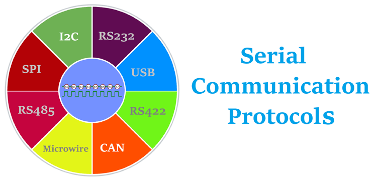
Types of communication protocols
There are different types of data transfer avaliable, such as serial and parallel communication. Same way, protocols are
divided in two types, serial and parallel communication protocols.
- Parallel communication protocols: ISA, ATA, SCSI, PCI, IEEE-488
- Serial communication protocols: CAN, ETHERNET, I2C, SPI, RS232, USB, 1-Wire, SATA
Transmission modes in serial communication
Serial communication data is sent in the form of bits (binary pulses), and binary one represents the logic HIGH and zero
represents the logic LOW. Depending on the type of transmission mode and data transfer there are several types of serial communication.
Transmission modes are classified as:
- Simplex method: either medium sender or receiver can be active at a time. Is one way communication, the sender transmit the data and
the receiver can only accept, and vice versa. (ex: tv and radio)
- Half duplex method:both sender and receiver can be active but not at the same time. If the sender is transmitting then the receiver can
accept but cannot send and vice versa (ex: internet)
- Full duplex method:both receiver and receiver can send data to each other at the same time. (ex:mobile phone)
Terms related to serial communication
- Baud rate:is a rate at which the data is transfered between the transmitter and receiver in the form of bits per second (bps). The most commonly used baud rate is 9600,
but there are others such as 1200, 2400, 4800, 57600, 115200. The more the baud rate the faster the data will be transfered ata a time.
It has to be the same for the trnasmitter and receiver.
- Framming: is reffered to the number of data bits to be sent from the transmitter to receiver. Most of the application uses 8 bits as the standard data bits but 5, 6 or 7 bit can also be selected.
- Synchronization:synchronization bits are important to select a chunk of data. It tells the start and end of the data bits.
- Error control: plays and important role while serial communication as there are many factors which affects and adds the noise in serial communication.
To get tid of this error the parity bits are used where parity will check for even and odd parity.
SYNCHRONOUS SERIAL PROTOCOLS
Serial communication protocols
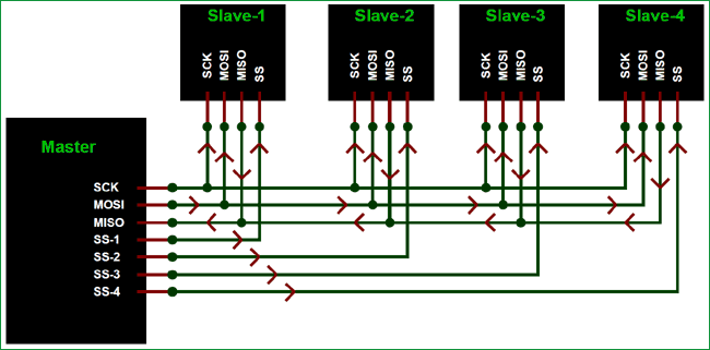
- SPI protocol: serial peripheral interface is a Synchronous interface which allows several SPI microcontrollers to be interconnected.
In SPI, separate wires are required for data and clock line. It can be configured either as master or as a slave.
The four basic SPI signals (MISO, MOSI, SCK and SS), VCC and GND are the part of data communication and needs 6 wires to send and receive data from slave to master.
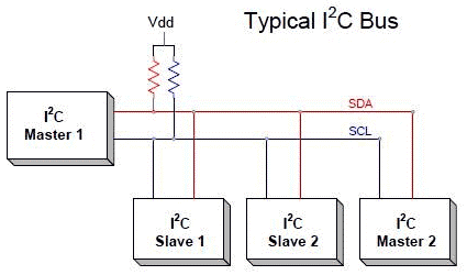
- I2C serial communication: inter integrated circuit is two-line communication between ICs or modules where two lines are SDA (serial data line) and SCL (serial clock line).
Both lines must be connected to a positive supply using a pull up resistor. I2C can deliver speed uo to 400kbps and it uses 10 bit or 7 bit addressing system to target a especific device on the i2c bus
so it can coonect up to 1024 devices. It is easy to set up since it uses only two wires.
- USB: universal serial bus is a protocol with different versions and speeds. It acts as "plug and play" and are used in many devices such as keyboards, printers, cameras, etc.
It uses two wires for data transfer and are faster than the serial and parallel interface.
*This information and diagrams were taken from Circuit digest
PROGRAMMING
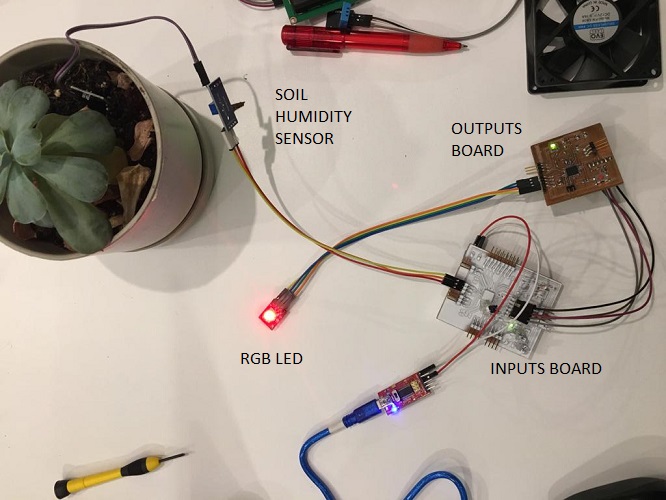
Fort his networking assignment, I want to connect my inputs (the white one) and outputs boards. The first one will receive information from the soil moisture sensor and the second one will turn red of the soil
needs water and green if it is ok.
Here you can find my inputs and outputs boards:
To program both boards I used the programmer developed in the electronics produccion week, the FabATinyISP.
This programmer is an AVR programmer which can be programmed via their SPI ports in conjunction with the RESET pin, using a SPI protocolIt uses 6 pins:
MISO, SCK, RST, VCC, MOSI, GND. Data is sent in series, this means there is a serial communication protocol.
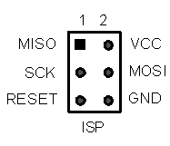
*This diagram was taken from Washington courses
CODING
It is neccesary to develop two codes and to programm each board individually: one for the sensors board (white one) and another one for the led board and upload them individually.
I based this code on our group assignment and my final project programming.
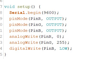
For the inputs board there is neccesary a "Send Only Software Serial" library for Arduino, which is used for situations where you need to do something sending but don't need to receive anything.
This lets you avoid tying up the pin-change interrupts for the receiving code. You can also download it Here.
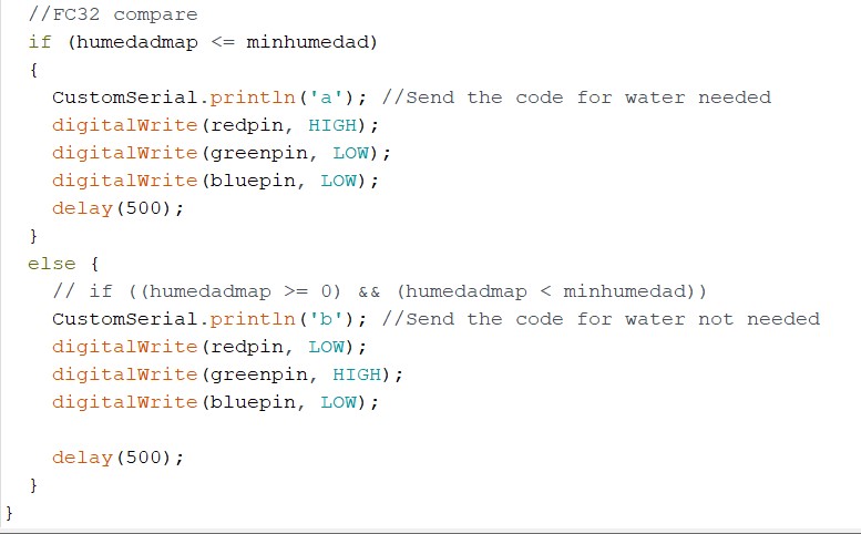
One important varible used here is CustomSerial.println('a') and CustomSerial.println('a') because this characters will be interpreted by the outputs board later. The vood loop conditions are set to determine
if the soil is dry or wet and depending on this condition the led will turn on red or green according to the soil conditions.
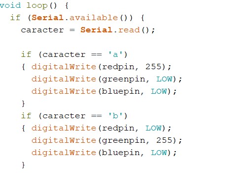
For the outputs board the code reads the caracter = Serial.read and interpret the values, if it is 'a' the led will turn red, since it didn't reach the parameters of humidity set before, or
green if the soil is wet, also according to the parameters set on the inputs code.
Here you can download both files:
Connecting my boards
The outputs board is connected to the white board (inputs) through the FTDI adapter, using 4 pins: VCC, GND, TX and RX (remember that Tx and Rx must be swapped).
The white board is connected through the terminal block to the programmer using VCC and GND. The programmer is connected through the USB to the computer to power the entire system.
This is the result of both of them working together:
troubleshooting
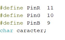
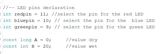
At first, the led only showed red, I realized that there was an inconsistency in the input variables vs. the outputs. In inputs I had the rgb determined as
"pinMode 'PinR, OUTPUT' and in outputs as 'int redpin = 11' (same for the other pins). So the first thing to do is to unify the name of the variables, leaving in both Codes like
'redpin', 'greenpin' and 'bluepin'.
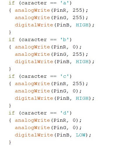
Then, the led only shoed blue, I realized that in the void setup I had analogWrite for red and green, and digital for blue, but all of my pins are digital, changed them all to digital.
After another test, I realized in the outputs I had foor characters with its own conditions while in the inputs I had just set two. So I changed it and just left it to be defined by 'a' and 'b'.
It is finaly working properlly.
Connecting my board through I2C
For this assignment Im going to use I2C Serial Bus to send and receive data between two micros just using two cables SCL for the clock signal and SDA (to send data).
The following image taken from Luis Llamas shows how this works
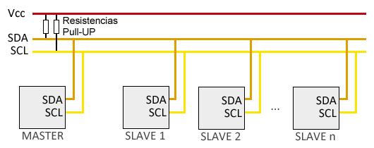
Each "secondary" has an address which is used to access the devices individually. The I2C bus has a master-slave architecture or as Neil recomends to call them a master-secondary architecture.
The master device initiates communication with the secondaries and can send or receive data from them. Secondaries can not initiate communication or talk to each other directly, the master has to ask them.
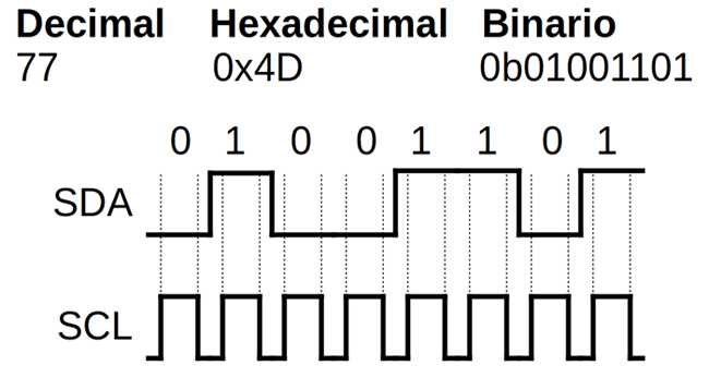
The I2C bus is synchronous which means that the master provides a clock signal that keeps all devices on the bus in sync.
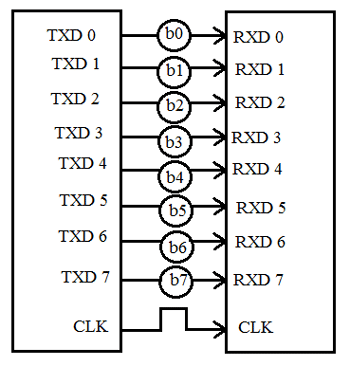
Each pulse on the SCL pin tells the receiving device to read the value from the SDA pin . In this way the bits are put into SDA one by one. The following image shows a transfer of the value 77, where the message is made
up of several frames or sections. A message is made up of an address frame which indicates to with secondary the information is sent.
connections
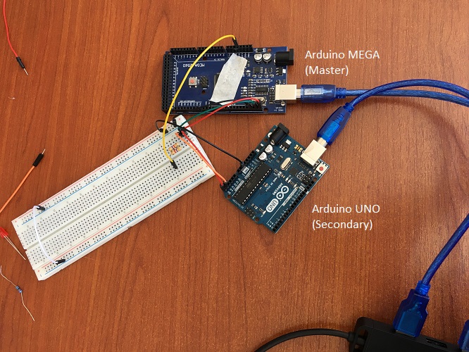
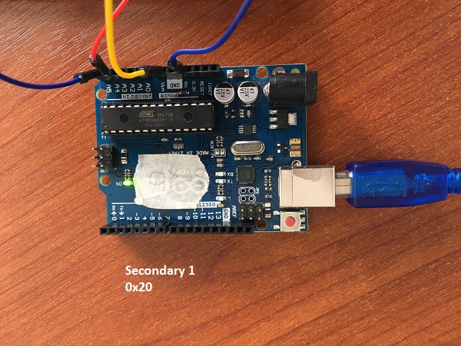
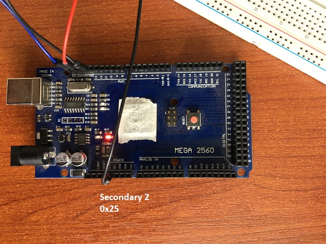
The board I designed and produced for my final project will act as master and I will use an Arduino UNO and Arduino MEGA as secondaries, since my outputs board does not have SDA and SCL pins avaliable and my inputs
board has a loose trace which causes unstable functioning.
- Danielas Board - pin27 (SDA) - pin28 (SCL)
- Arduino UNO - A4 (SDA) - A5 (SCL)
- Arduino MEGA 2560 - A4 (SDA) - A5 (SCL)
- It is also neccesary to place two pull-up 4.7kΩ resistors between each line and the supply
- Cables for connections
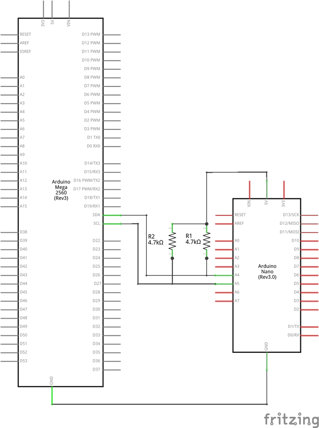
*Images taken from Programar fácilArduino - I2C Communication
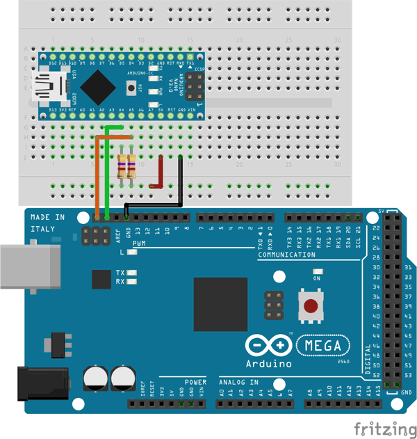
To try the example we found we started using just an Arduino MEGA (as master) and an Arduino UNO (as secondary) to try the communication between them.
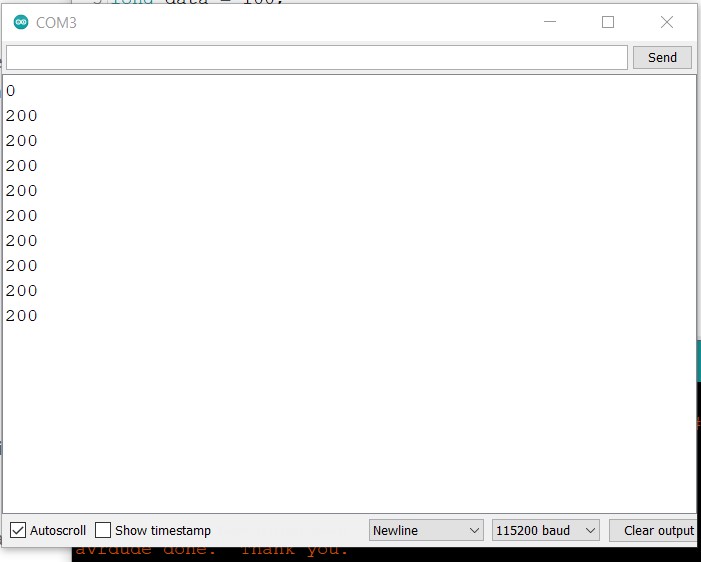
Programming is pretty simple with Arduino IDE, and once both are connected they send data that can be read trough th serial monitor.
To generate the code it is neccesary the wire library to interact with the I2C bus with Arduino, it does not need to be installed since it comes b default with the Arduino IDE software.
Master
#include "Wire.h"
const byte I2C_SLAVE_ADDR = 0x20;
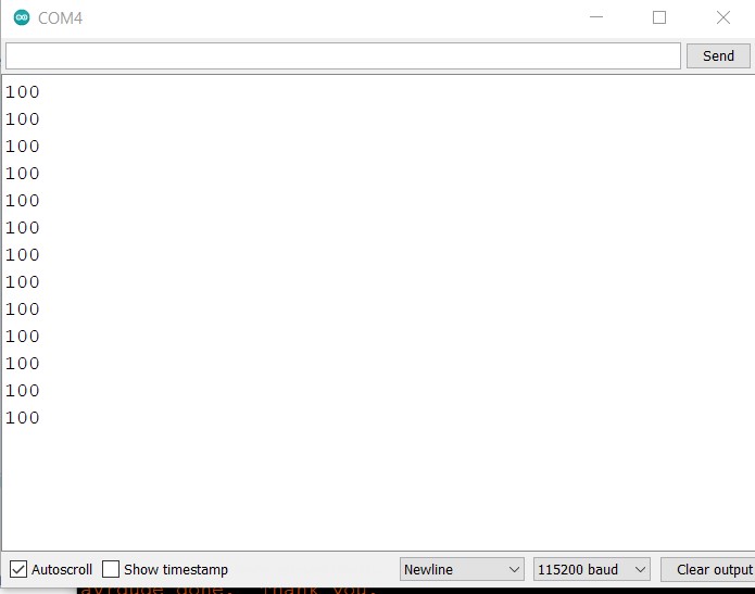
long data = 100;
long response = 0;
void setup()
{
Serial.begin(115200);
Wire.begin();
}
void loop()
{
sendToSlave();
requestToSlave();
delay(2000);
}
void sendToSlave()
{
Wire.beginTransmission(I2C_SLAVE_ADDR);
Wire.write((byte*)&data, sizeof(data));
Wire.endTransmission();
}
void requestToSlave()
{
response = 0;
Wire.requestFrom(I2C_SLAVE_ADDR, sizeof(response));
uint8_t index = 0;
byte* pointer = (byte*)&response;
while (Wire.available())
{
*(pointer + index) = (byte)Wire.read();
index++;
}
Serial.println(response);
}
Secondary
#include "Wire.h"

const byte I2C_SLAVE_ADDR = 0x20;

void setup()
{
    Serial.begin(115200);

    Wire.begin(I2C_SLAVE_ADDR);
    Wire.onReceive(receiveEvent);
    Wire.onRequest(requestEvent);
}

long data = 0;
long response = 200;

void receiveEvent(int bytes)
{
    data = 0;
    uint8_t index = 0;
    while (Wire.available())
    {
        byte* pointer = (byte*)&data;
        *(pointer + index) = (byte)Wire.read();
        index++;
    }
}

void requestEvent()
{
    Wire.write((byte*)&response, sizeof(response));
}


void loop() {

    if (data != 0)
    {
        Serial.println(data);
        data = 0;
    }
}
You can find this ino files here:
What I understand/learned from this outcome:
- We are using 115200bauds, this specifies how fast data is sent over a serial line. It is important to remember that both devices operate at the same rate.
- The higher a baud rate goes, the faster data is sent - received
From master's code:
- Wire.begin starts the I2C communication
- sendToSlave initiates communication to the secondary, transmitting bytes in the long variable
- requestToSlave, asks the secondary a number of bytes
From secondary's code:
- The secondary starts the Is2C bus with begin(ADDRESS), in this case I2C_SLAVE_ADDR
- onReceive collects data sent from the master and save them in the data variable, shown in the serial monitor
- onRequest sends the variable "response"
Adding Daniela's board
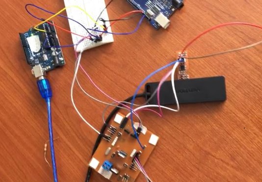
Next thing we tryed was setting my board as master and both Arduinos as secondaries. To upload the code to my board I used the ISP programmer developed in previous weeks
which uses MISO, SCK, RST, VCC, MOSI and GND.
Powered the Arduino UNO with an USB cable, powered the Arduino MEGA through a proto board and powered my board through FTDI with a programmer connected to the USB Port (I just have two ports on my computer).
Also, added the resistors following the previous diagram.
Using the previous code we made some modifications to set a second seconday in this case the Arduino Mega.
For the secondary's code we added the void luces taken from Arduino blink examples in order the turn on the leds when receiving data. We set the Arduino UNO
as the secondary 1 and the Arduino MEGA as secondary 2.
This is the result:
In Arduino IDE it is important to remember:
When programming with IPS in tools you must select:
For Daniela's board
- Board:Arduino Nano
- Processor: ATmega328P (old bootloader)
- Programmer: USBTinyISP
- There wont be a Port
- And to program> Sketch > Upload Using programmer
This is different when programming the Arduinos:
For the Arduino UNO:
- Board:Arduino UNO
- Port: select one
- Programmer: AVRISP mkll
For the Arduino MEGA:
- Board:Arduino MEGA or MEGA2560
- Processor: ATmega2560
- Port: select one
- Programmer: AVRISP mkll
This is the code we used:
Usefull sites
These sites have been really usefull troughout this process:
AranaCorpMultiple Arduinos with I2C Bus
Luis Llamas How to connect two Arduinos with I2C Bus
Programar fácilArduino - I2C Communication
troubleshooting
Some times it turns so hard to discover where the problem is.
- During the initial tests between Arduinos and my board we had a communication problem since the data was sent only once and we had to reprogram in each attempt,
or there was only communication between master and secondary but not biseverse. We tried several things to solve this: disconnect and reconnect, change cables,
change resistors, measure continuity, check pins, and we could not identify the problem. After several attempts we realized that the problem was with the usb hub.
My computer has only two USB ports and through the hub we connected 2 components and this was causing a conflict. To solve this we decided to provide the power of
the third component through the proto board.
- During the continuity check of all the components, we checked the programmer that was connected to the master board and it had a short circuit,
we replaced it with another one.
some thoughts about this week
This task was very challenging for me, since code generation is a language that I have not mastered yet. For this reason I have left it to the end.
After developing my final project, Diego's support, constant consultations about the concepts, a lot of time connecting and disconnecting my boards, correct answers,
mistakes, tests and more tests, I have finally achieved it. It is still a long way to go but I am glad I made it.