PROJECT DEVELOPMENT
Here is where I will document the entire progress on my final project.
For an insight on the planning process check out Week 17: Applications & Implications. To see my presentation video and slide, jump to the Final Project Results page.
Ideas
In the beginning of FabAcademy I had a few ideas of what I wanted to do for my final project. See Week 01: Principles & Practices for my early ideas. Around Week 08 my final project ideas really started to formulate. I partnered up with Amanda to build a sort of pavilion-like structure out of plywood on the CNC router. We went through a brainstorming process with a lot of visual research to help us decide how we wanted the structure to look. We took inspiration from large scale modular projects such as these and more.
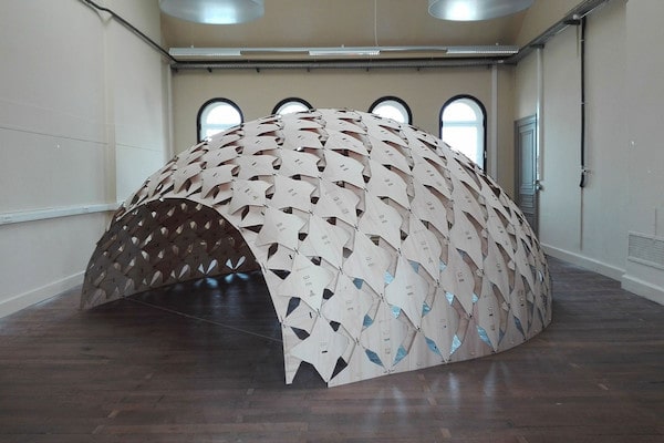
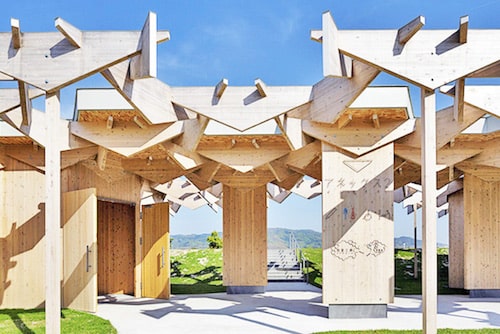
Sources: Left Van Dousselaere & Van Geeteruyen and Right Kengo Kuma
Ultimately, our structure's shape was driven by what we could make on our CNC machine. The 3-axis Axiom has a 2' by 4' bed, so we can only make individual shapes smaller than that. However, through modular design we can make larger constructions. Also, we decided we wanted our "pavilion" structure to be semi enclosed via a dome-like shape, and we wanted it to be sit-able. This next image of an outdoor seating pod by David Kelly is what we modeled the top half of our design on.
See Week 17: Applications & Implications for an explanation of how we differentiated our design.
In this early brainstorming stage, we also came up with additional ideas for the design and functional aspects of the structure, but I'll go into those as they become more relevant in our construction process.
CNC Structure
Dome
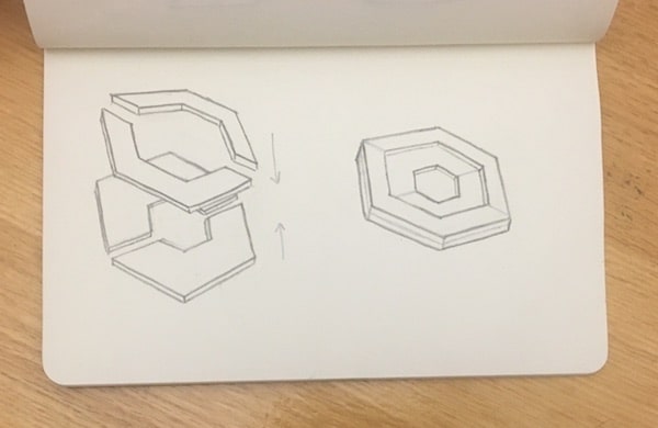
In Week 08: Computer Controlled Machining I worked on creating the main dome part of the "pavilion". Here are some sketches I drew of the dome with various possible designs for the individual hexagon panel shapes.
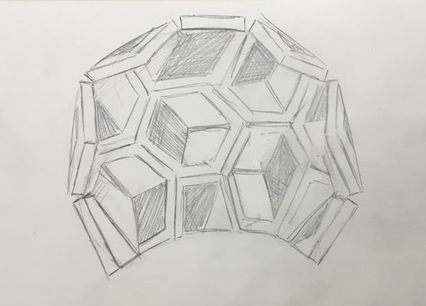
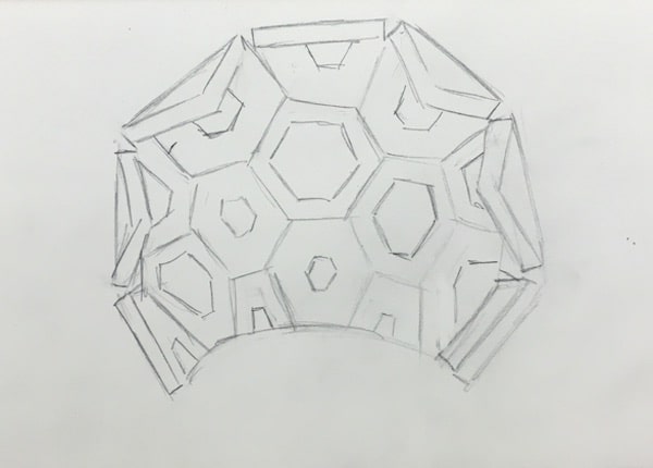
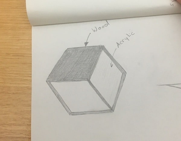
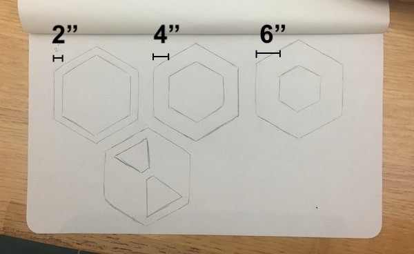
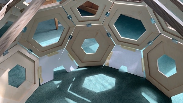
We went with a design like the ones on the right where each unit is made up of a hollow hexagon with borders ranging from 2", 4", and 6". Once we knew how the overall skeletal sort of frame would look, we broke it down into parts that would be manufacturable on the CNC and easy to assemble together. Our structure is made up of multiple hexagon and pentagon shapes and those modular units could be cut on a CNC individually, but we divided them up further so that each hexagon or pentagon was cut in half. This allowed us to nest them better in Fusion and it let us make the units slightly larger. We also gave each hexagon unit a second layer, with a 2" border, so that we could glue together the parts with an offset seam. See the illustration below. One of the reasons for the different widths for the hexagon parts was that we planned to install acrylic windows in some of the openings and the different sizes would make that easier.
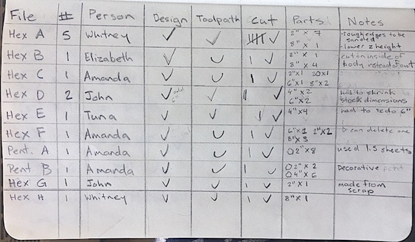
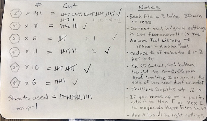
Take a look at Week 08 which shows how I created designs and manufacturing toolpaths for the cutout shapes in Fusion360. Because this structure was so large, Amanda and I worked with a group of three other students to do prepare and run the cutting files. However, because there were multiple design files to cut, we each got a chance to work on building 2D parametric designs, setting up toolpaths in Fusion's Manufacturing mode, and running jobs on the CNC individually. Here's a couple pages from my notebook showing how we divided up the work and tracked the progress of our cuts.
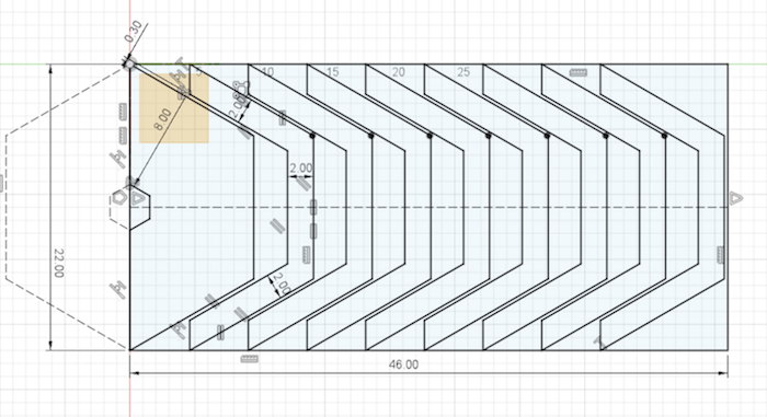
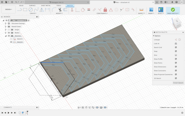
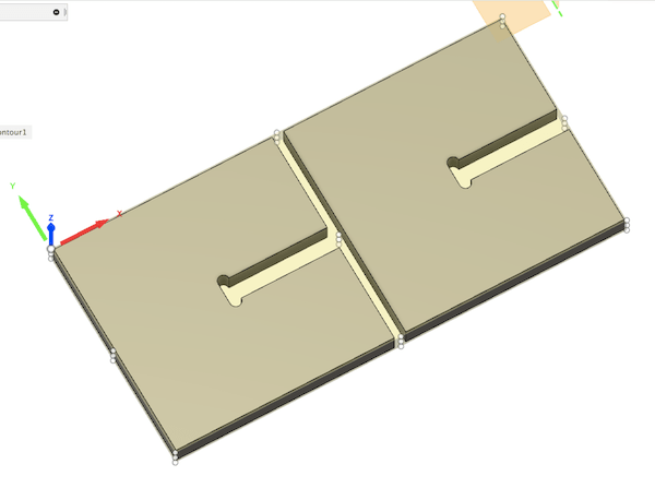
This is one of the files that I prepared in Fusion and cut on the CNC. It shows how I nested the hexagon parts, and used parametric design.
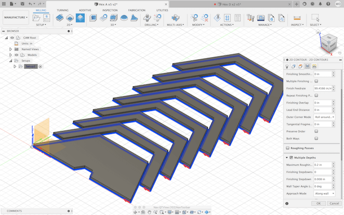
After that, I set up a 2D Contour toolpath in the Manufacturing mode. Again, check out Week 08 to see the details about how I did this.
I saved the generated NC code to a flashdrive to run on the Axiom. This whole Fusion set up was done multiple times, to create about 10 different files. We had 20 sheets of 1/2" x 2' x 4' plywood alotted to us and we managed to use up 15 sheets for this section of our project (some files were cut multiple times since we needed many of those parts).
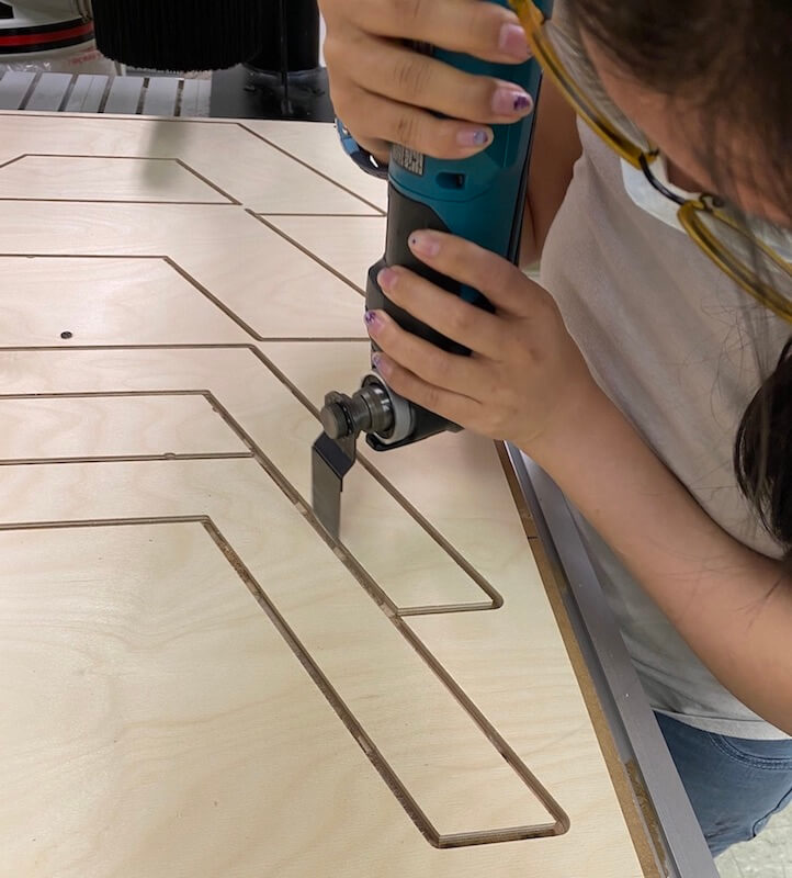
At the Axiom, I prepared the machine by securing the stock, inserting the 1/4" endmill, and setting the origin and Z height. We ran into various problems, such as bits breaking, and feed rate running too slow. Some issues had to do with our tool settings or general set up, others are mysteries of the machine, but we managed to work around those too by editing the NC code. You can read all about these conundrums in Week 08.
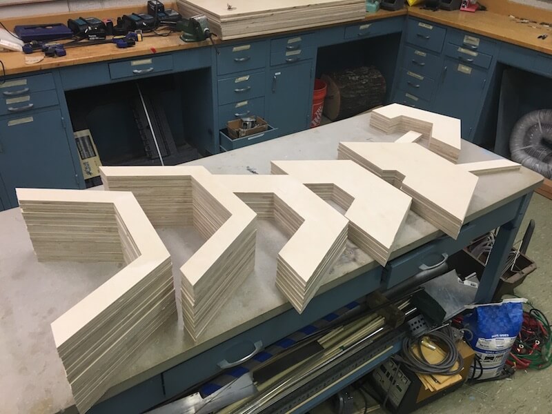
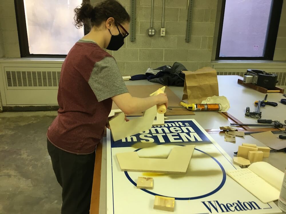
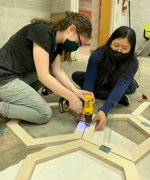
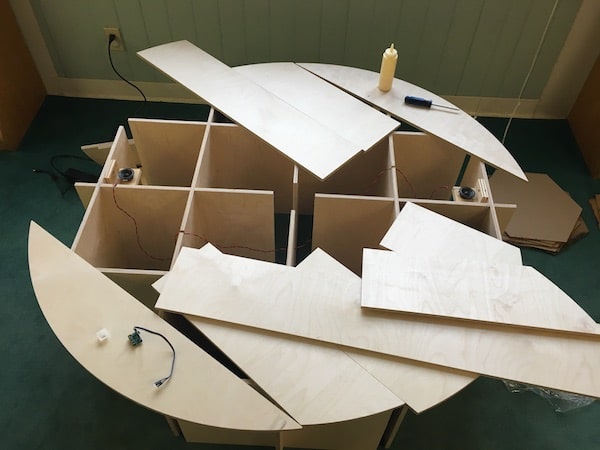
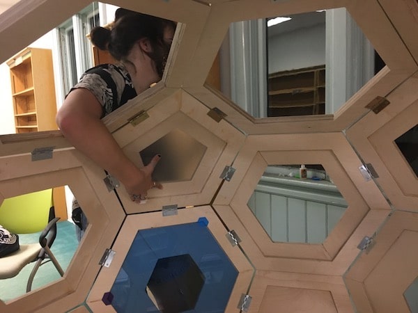
We spent some time cleaning up the tabs and glueing the shapes together. After that we attached the units to each other with screws and hinges.
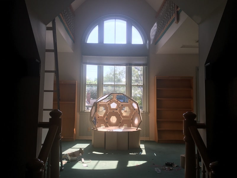
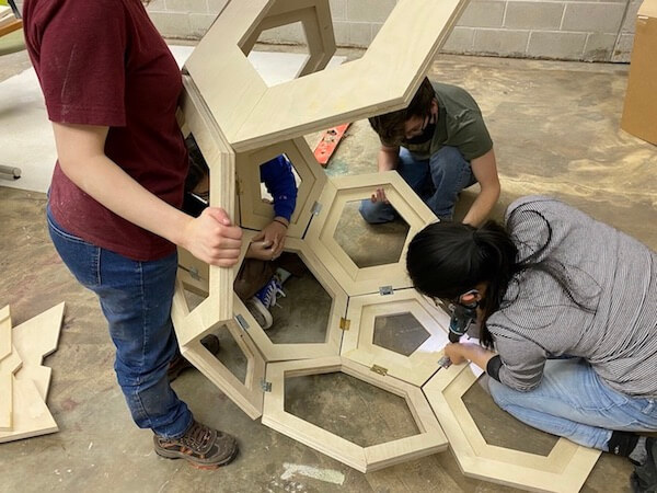
Wrangling the dome was definitely a five person job! It was helpful having a bunch of people support the dome while we flippped it upside down to attach the sides.
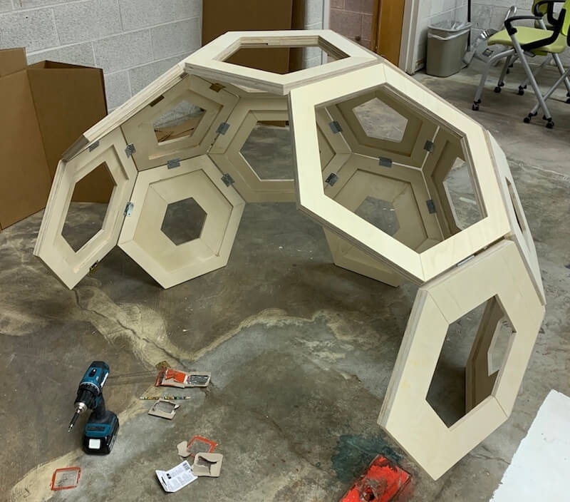
And for scale!
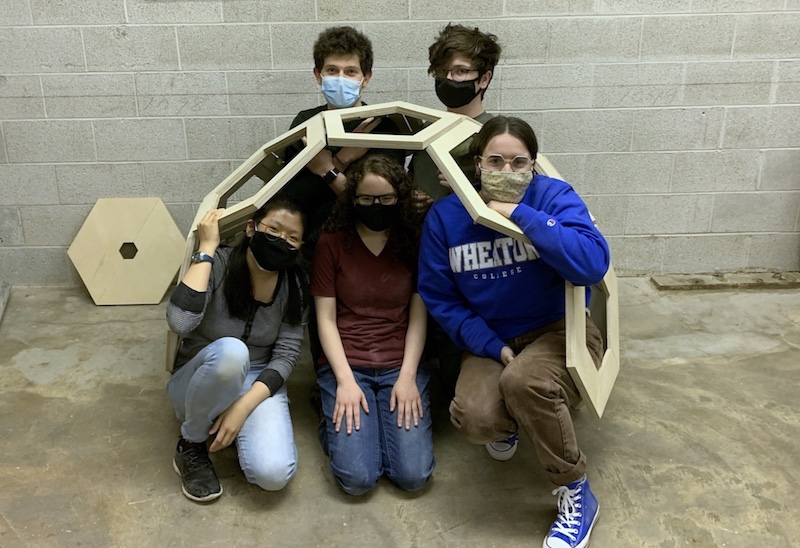
We learned a few things from building the dome that would help us with the rest of our project. For instance, once the dome was physically constructed, we got a better sense of its scale. As you can see, 5 people can fit inside it! But more comfortably 2 or 3. We also learned something interesting about geometry as we had tried to fit half hexagon shapes into the gaps on the bottom of our dome, but those where meant to be pentagons, so Amanda re-created those and we added them in later.
In addition, we had a few different ideas early on of how this structure would be used and where it would go (inside, outside?), but once we saw it in person, my partner and I figured it made sense to develop this as an indoor seating area. Also, the whole structure felt pretty low to the ground, so we decided to build a base to raise it up.
Base and 3D model
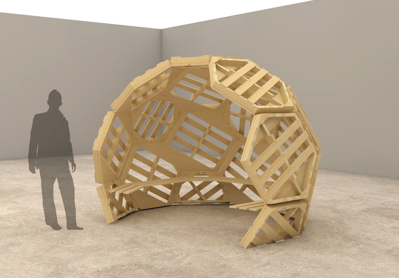
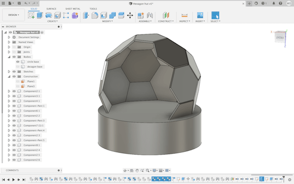
During the Computer Controlled Machining week, I had started to build a 3D model of the dome structure. I revisited this when it was time to design the base structure. For the most part, I created the dome in Fusion by extruding hexagons and pentagons, aligning them on their edges, and using the "Joint" feature (under "Assemble") to tilt them to the correct angle. The cylindrical base here is just a placeholder.
I designed a press fit base using the same 1/2" plywood as the rest of the dome. These are some sketches that show my ideas for the base structure from an arial view. The first image is the press fit base and the second is the floor board arrangement.
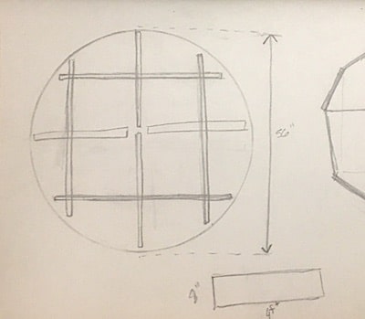
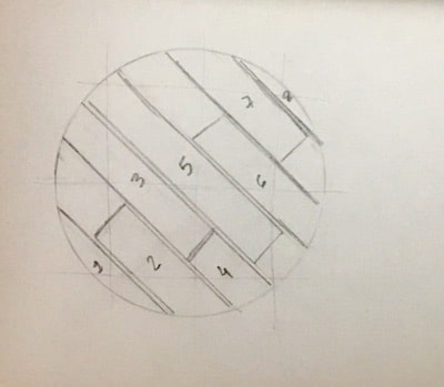
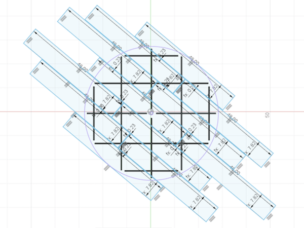
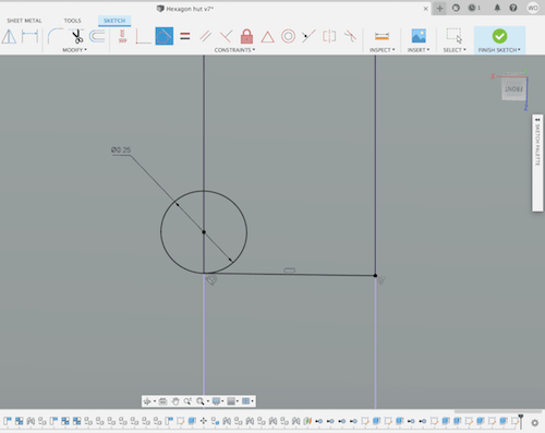
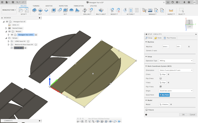
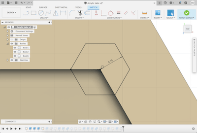
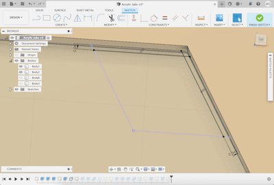
Here it is the sketch in Fusion. I made a circle with a diameter larger than the dome's, with thin rectangles (1/2" since that's the thickness of the plywood) which I duplicated in a circular pattern. I was consious of the fact that I was using plywood sheets that were only 48" long. That's why the cross doesn't meet in the middle, it wouldn't extend that far. Also, I added floor board planks.
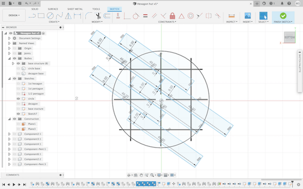
However, after sketching this out, I was unsure if the base would be strong enough with 1/2" plywood spread out in this way, so I added more press fit supports. This was really easy to revise with parametric design.
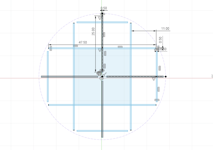
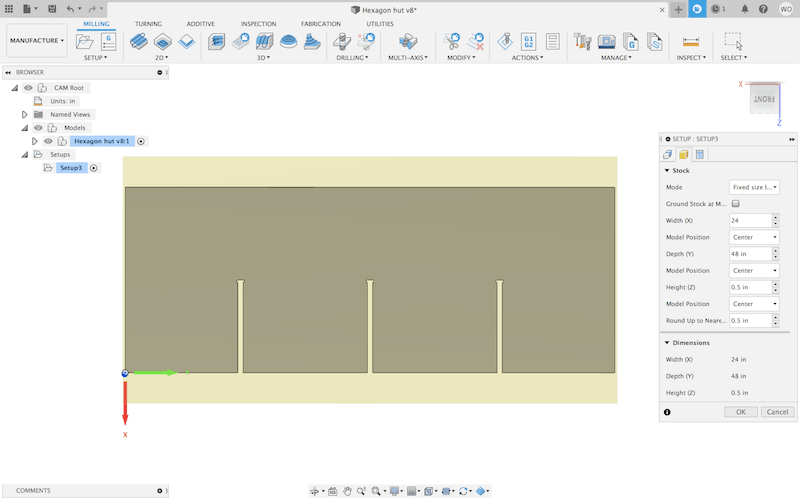
Notice the floor boards are just less than 8" wide. This was so I could fit 3 planks on a 24" wide plywood sheet and still have room for the 1/4" endmill. Also, I arranged the floor boards so that their ends would be supported on the wood below. I used the circle, projected from a previous sketch, as the rounded sides of the floor.
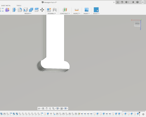
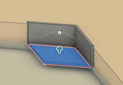
Once I had the sketches of the floor and supports, I extruded the press fit grid to be a good height for a chair, 18", and extruded the floor boards in the opposite direction to a 1/2".
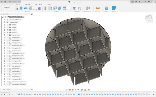
By then, I had rough 3D model of our entire design.
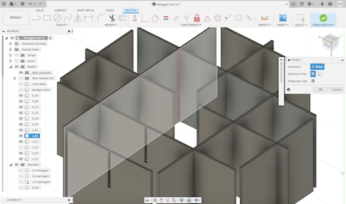
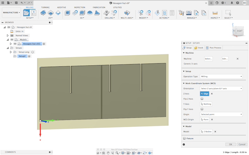
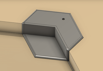
The next step was to turn the grid supports into press fit construction parts by adding slots. I selected one of the faces of the rectangle supports and used the "Project" tool to draw lines at all of the places where grid intersects this face. Then, I found the half way point at each of these lines and created a rectangles from the edge of the shape to this halfway point, with a 1/2" width for the thickness of the wood.
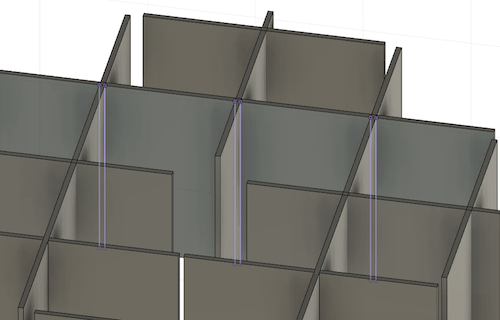
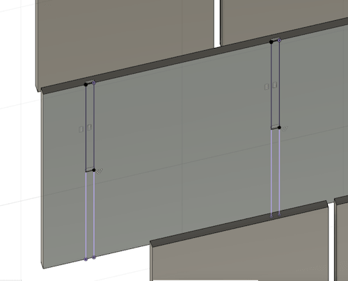
To make the assembly go more smoothly, I added dogbones to account for the round shape of the endmill at these tight corners.
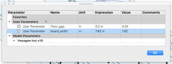
Since the base is made up of multiples, I only needed to make the press fit slots once on each of the differently sized rectangles. (Unfortunatly it took me a while to realize this). Before making these cuts on large sheets of wood, I made a test of the press fit joints using the same type of wood. I found that the slots, when drawn to exactly to the thickness of the wood (.5 in), was too loose, so I adjusted the gap to be .48 in. This worked, so I applied it to my design.
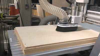
Next up was making the toolpaths. I used all of the same settings and processes to use the Axiom as I did in the Computer Controlled Machining week, which you can read about here. We used up 8 sheets of 2' x 4' plywood for the base and 4 sheets for the floor boards. Also, Amanda made some files to cut out the rest of the half pentagons and those took up 2 sheets.
We ran into some issues at the Axiom where machine said we were out of bounds in either the X or Y directions. This happened because some of the designs were just barely too long, so it was out of range of the axes. Sometimes we could fix this just by shifing our origin point, but other times I had to edit the design to be sightly smaller.
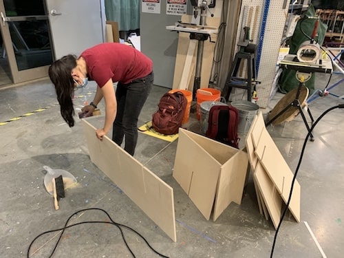
After making the cuts on the CNC router, we lightly sanded down the edges and then the parts were ready to assemble. This was a fun part, literaly piecing things together and seeing our project take a physical form. The press fit joints were not too difficult, especially with the dog bone cuts, but they were definitly snug and we needed a hammer. The floor boards were simply attached with wood glue.
Electronics: PCB Fabrication
Between Amanda and I, we divided our project so that she would develop the lighting system with the Neopixels and I would do the electronics production for the audio system. We had several initial ideas for how users would interact with our project's functional aspect, but we decided on having two sets of Neopixels, a string of fairy lights hung around the inside of the dome and a regular strip along the edge of the base. These would be controlled by two buttons, one for the top and another for the bottom. The buttons allow the user to toggle between different types of light patterns. The sound would be activated by a passive IR sensor.
Circuit Board Design & CAM
For the sound system I had hoped to build off of the work I had done in Outputs Week by storing WAV file songs on an SD card and playing them via a remote control. This would have allowed for us to play any song or background music in our sound system. I'll explain later how this did not work out, but I designed a circuit board with the pin connections to enable both an SD card reader and an IR receiver for a remote control. Here is the PCB schematics layout. Also, check out Week 07: Electronics Design to see details on how I learned to design boards in KiCad.
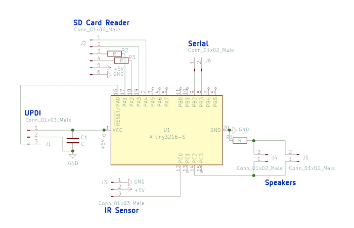
As you can see, I have a UPDI connection with a capacitor between GND and VCC, an IR sensor/receiver, two speakers connected in parallel with a resistor to protect the speakers and microcontroller. The RX and TX, serial connections did not end up being used in the final version of our project, but I added them in case I needed them for programming. Back in Week 13, I learned how to connect an SD card reader to a microcontroller with MISO and MOSI. Note that R2 and R3 are just 0Ω resistors that I needed for routing. Below is a snapshop of routing the traces and the finished footprint diagram.
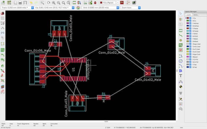

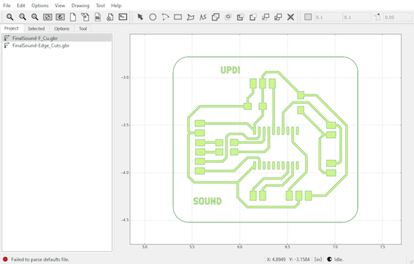
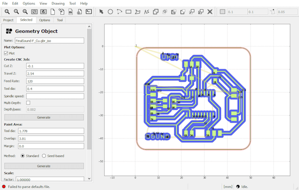
I exported this design as a gerber file and completed the CAM in FlatCAM. I used the same process to generate the NC code for the Roland as I did during Week 07.
PCB Milling & Soldering
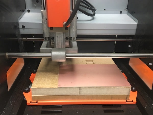
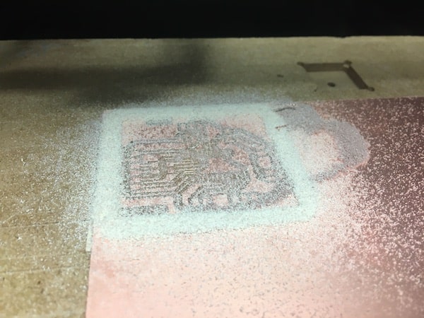
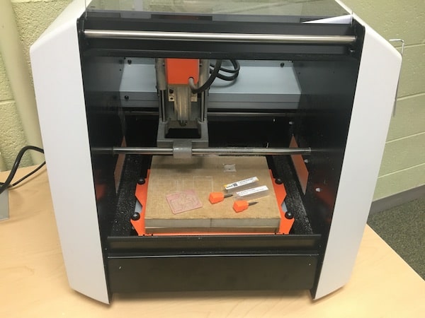
At the Roland mill I set up my workspace by securing the copper board and setting the origin and Z height. I used a 1/32" carbide ball nose endmill for the traces.
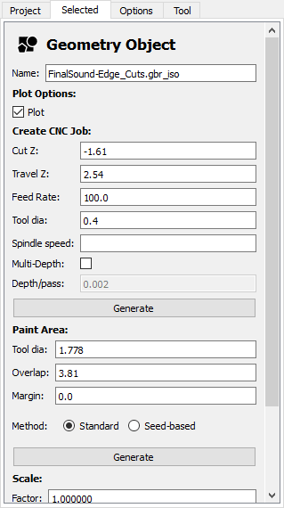
The first time I tried running the file, I found that the endmill was hardly scratching the copper. So, I lowered the Z height in FlatCAM until the traces cut through. Below, are the settings I used for the traces and edge cuts.
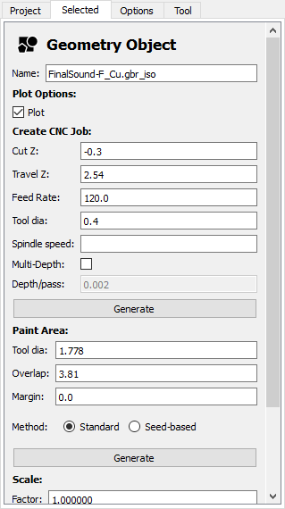
So, with those modifications the traces cut well.
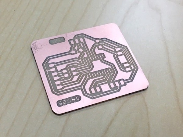
After the traces I switched out the bit for a flat endmill to do the edge cutout with. These were the tools I used.
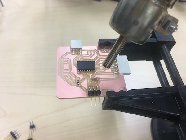
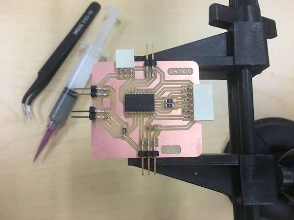
My milled board. Next, I soldered the components onto the board. I used an ATtiny3216 as my microcontroller, a 100Ω resistor attached to the speaker connections on the left, a 0.1uF capacitor, some 0Ω resistors, and a bunch of male and female header pins.
Electronics: Programming
Now with a fully soldered board, I tested it using a piezo buzzer and the ToneMelody sketch from Arduino. Using the Arduino IDE, I compiled and uploaded the sample code. I learned how to program my board in this way during Week 07, also I used piezo speakers and the tone() function during Machine Building week
This worked well, so I tried to use the the SD card reader on my board. Back in Outputs week, I had successfully connected an SD card reader to an Arduino board and I could play WAV files off of that. When I tried to do the same thing on my board I got error messages that the library I was using to play WAV files, TMRpcm, was incompatible with my board's architecture. I had this same issue in Week 13 which you can read about here, and at the time I thought I might be able to fix it by using a different library. However, after doing some research I found out other people have had this problem too, including past FabAcademy students, and there wasn't a great solution other than building a whole new library that works for my type of microcontroller. So, with that knowlege I shifted into making an audio system that uses the tone() feature in Arduino.
At this point I thought I could maybe still use a remote control with beep tone songs, but I ran into a similar issue with libraries. Uhg. Eventhough I didn't get to use this in my final project, I learned how remote controls operate and I programmed this on an Arduino. (I know this has nothing to do with my final project, but I'm showing it here cus I think it's cool).
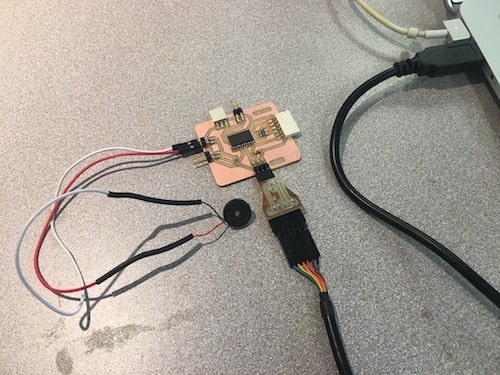
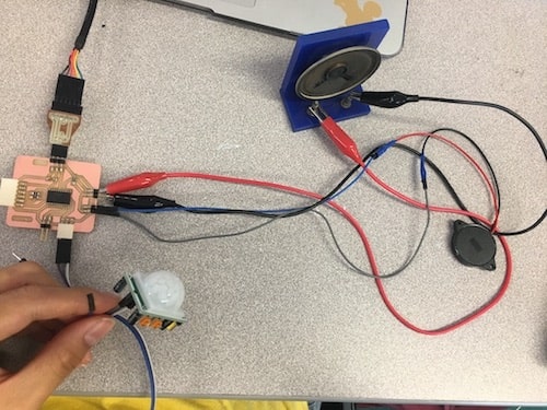
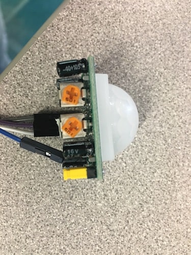
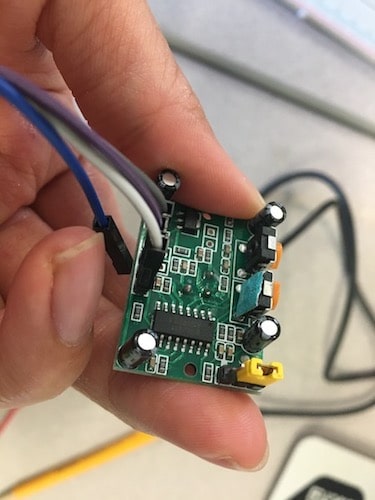
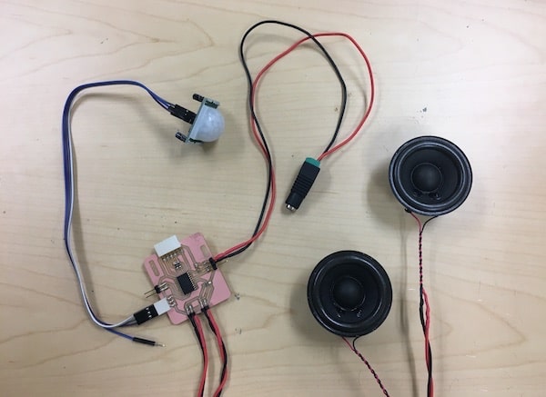
Eventually, I decided to operate the sound effects via a passive IR sensor. On my board, I had a 1x3 female pin header (connected to VCC, GND, and data). I had used this to try out the IR receiver for the remote control, but now I am using it for the passive IR sensor. Here, I am connecting the sensor to my board, and I'm using the RX and TX pins to make a serial connection so that I can print things to the serial monitor in the test code below.
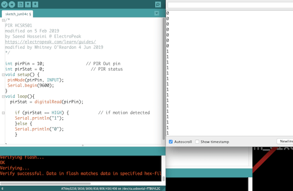
When I held my hand in front of the sensor, a string of "1"s were printed to the serial monitor to signify that the IR sensor's digital read status had gone from LOW to HIGH.
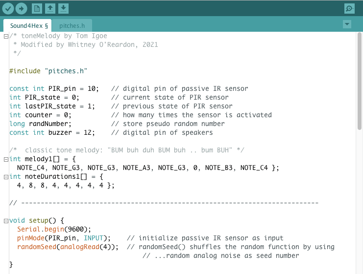
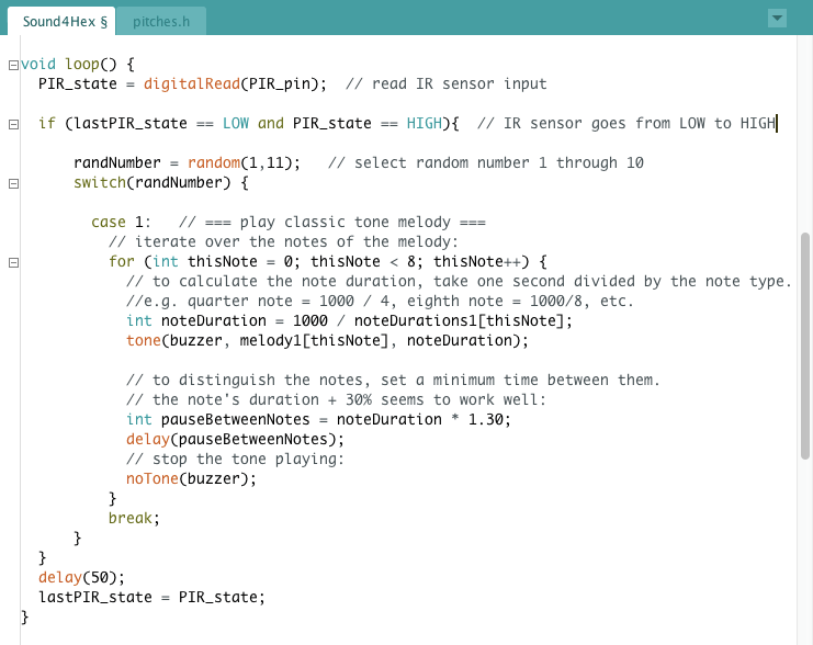
Next, I wanted to make it so that someone could trigger the IR sensor to play a random tune. Below, I used the random() function and a switch statement to create the basic structure of my code. In each loop, I'm generating a semi-random number and depending on what that number is, the code will do something different.
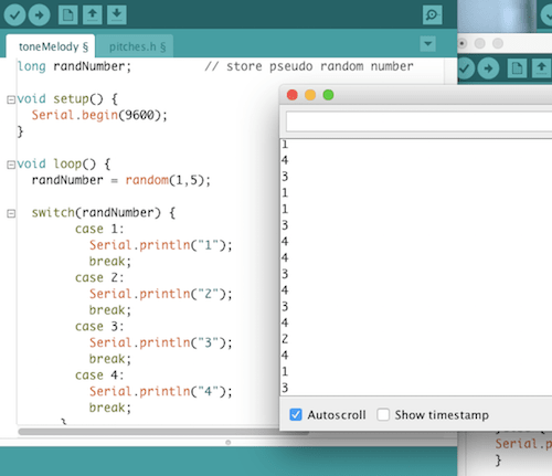
I combined this with the code for the ToneMelody sketch and the IR sensor. In the program below I show one switch statement case for brevity, but I can add as many statements as I wish. My later code (attached under Design Files) has ten cases, with a Tone() song attached to each.
A really cool resource I found was Robson Couto's collection of songs transcribed into Arduino code. I used many of these in my final program, along with some songs I coded myself (see Week 13).
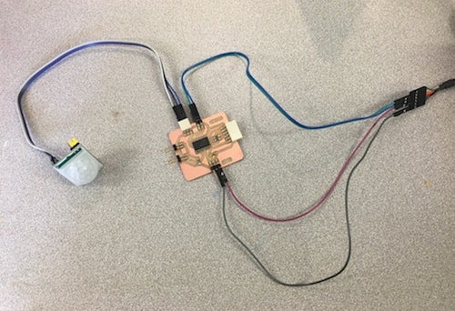
So, with my board programmed with the speakers, IR sensor, and random song generator, I tested it by walking in front of the sensor.
By doing this a bunch of times I got a a better sense of how wide and far the sensor's range is. Sometimes, people would walk aross the room 20 ft away and the speaker would start singing. In addition, the sensor has two potentiometers where you can adjust the sensitivity and time delay of the sensor. I played around with these knobs to get the sensor the activate quickly when someone comes into close proximity (these settings are shown below). Also, I couldn't find the datasheet for this particular brand of PIR sensors, but I discovered through trial and error that the bottom knob, marked with tape, is the time delay one and the other is sensitivity adjust.
As a note, when I was doing the electronics for the sound and IR sensor, my partner, Amanda, was working on the board to control the Neopixels.
System Integration Pt I
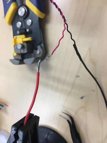
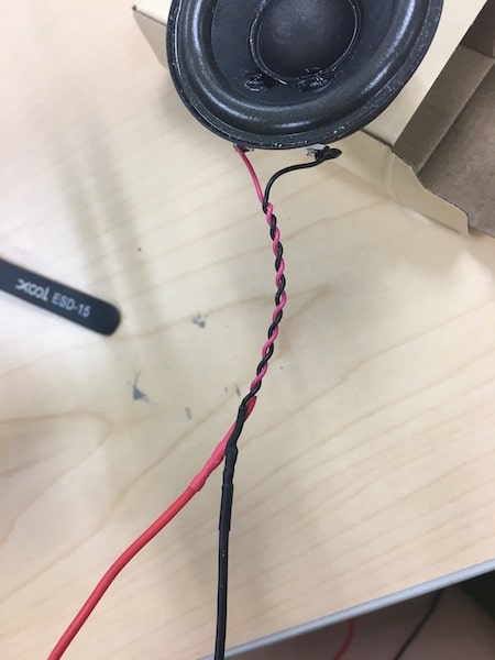
Yay! My code was working! Next, I worked on installing my sound system into my group's physical design. One of the things I needed to do was extend the wires connecting the speakers and the circuit board. Amanda and I discussed having a user control panel on the lower left, inside part of the dome. This would house our buttons for the lights and the passive IR sensor. It would also be the point where the two speakers were connected, in parallel, to my board. I had intended for the speakers to play in sinc on opposite ends of the dome, so I attached power and ground wires to each speaker, long enough to reach across.
Then for power, I attached another pair of wires to GND and VCC on my board. This leads to a screw terminal to barrel jack connector that plugs into a power supply that I will share with the Neopixels. The Neopixels require a lot of power, so to be on the safe side we bought a 15A 5V power supply adapter.
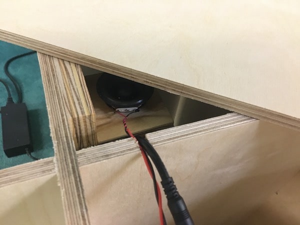
I made some little shelves with holes for the speakers to fit inside. Then, I attached these to the interior of the base. Since some wires needed to cross over the grid lines, I drilled away part of the wood so the cords wouldn't get crushed by the floor boards.
When I laid down the floor boards, I left two panels unglued so that we would have better access to the electronic systems in the future. You can see one of the speakers through the gap in the floor boards. Also, the black box to the left is the power supply.
Laser Cutting
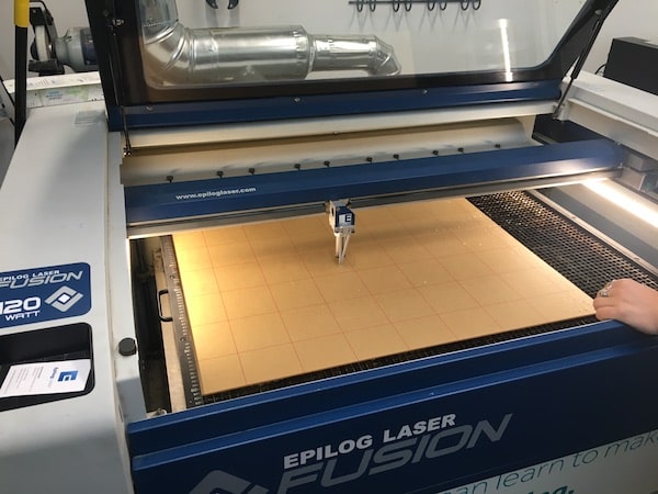
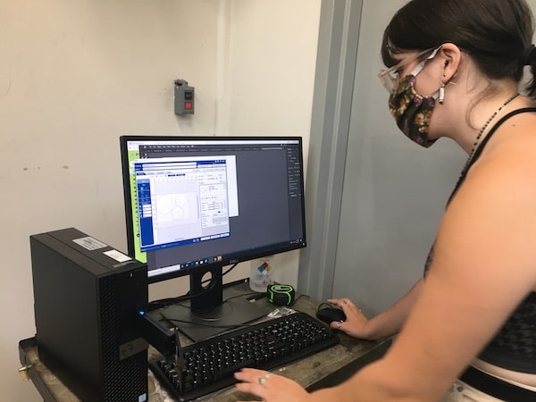
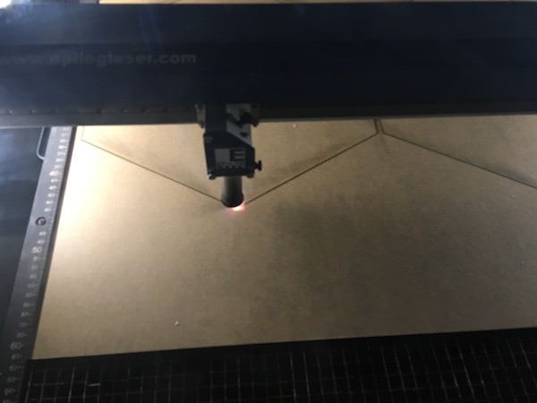
Another part of Amanda's and my design plan was to place colored acylic panels in the windows of the dome. Amanda created the 2D design files for cutting out the hexagon and pentagon shapes pieces, but I helped to run the files on the Epilog Laser. Check out my Week 04 on computer controlled cutting to see how we set up and use the laser cutter.
Here, we're focusing the laser and choosing the speed, power, and frequency for the vector cuts (10S, 90P, 100F).
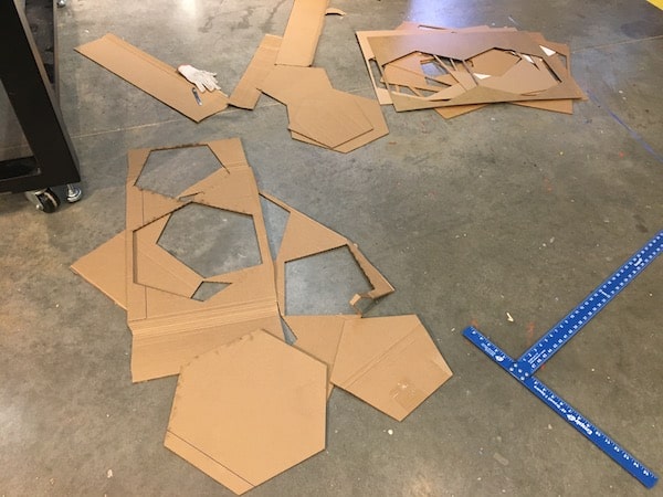
These are some of the cuts.
3D Printing
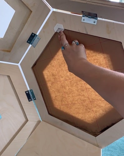
With all of these acrylic panels, we needed some way to secure them. Given our clear acrylic, it would have been ugly to glue the entire face of ofthe acrylic to the wod behind it. Also, some of the window gaps don't have any border to secure things to. Our solution to this was these 3D printed "picture frame" hooks. They go on three corners of a hexagon and get hot glued to the acrylic and wood just under those areas.
This is something that I modeled for the 3D printer. I checked the dimensions of our actual hexagon units to design a little corner piece that would fit tightly against the wood and acrylic below.
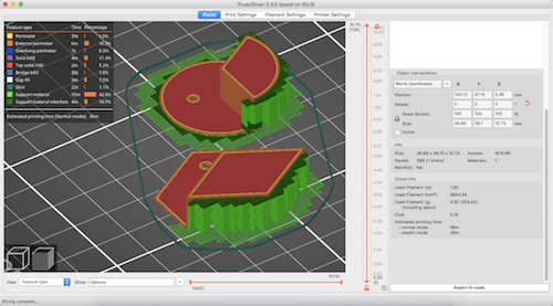
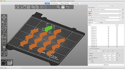
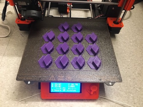
I saved this model as an STL and used PrusaSlicer to prepare it for printing. Since the model has an overhang, I used supports. Also, to make the print go faster, I made it at 0.3mm layer height. The circular model below was another test for the hooks, but we didn't end up using it.
After this printed, we tried it out on the wood and it fit great with the acrylic, so Amanda and I printed a bunch more.
I printed a plate of 14 hooks, and Amanda ran two more jobs like this. I did this on Prusa MK3 MMU2 with PLA filament. To see how I prepare a print on the MMU2, check out Week 06.
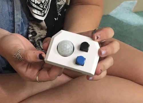
Another 3D printed component was the user control panel to house the IR sensor and buttons for the lights (top button changes the fairy lights, bottom one changes the base lights). This panel was something that Amanda made the design for and printed.
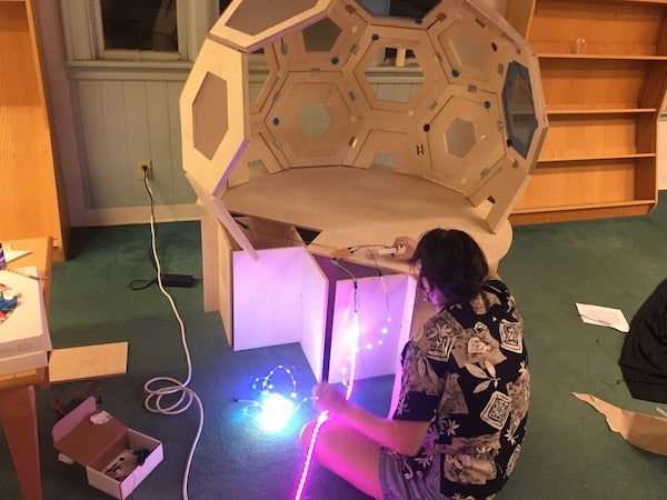
System Integration Part II
Here we are, attaching the acrylic panels with the hooks. Also, Amanda is testing the lights with our shared power supply.
We worked together on assembling the various parts. Check out this time lapse video of us.
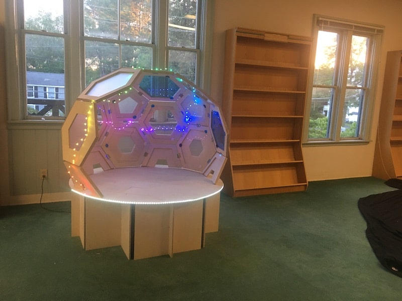
The final product turned out awesome! I'm really happy with our design and the effects of the lights and sound. The sound is audible in the second video, but I realize we entombed the speakers so it's a bit soft. For more info on the Neopixels and their operation, check out Amanda's page.
For more reflections, go over to my Final Project Results page.
Resources
- Principles & Practices
- Computer Controlled Cutting
- 3D Printing
- Electronics Design
- Computer Controlled Machining
- Mechanical and Machine Design
- Outputs
- Applications & Implications
Design Files
Main structure
2D design and toolpath for some modular hexagon units
Hexagon_hut.f3d
3D model of the whole structure. It includes 2D design and toolpaths for the base and floorboards
Schematics and footprint diagram for the "Sound" board
Gerber_Sound.zip
Gerber files for the traces and outline
Arduino_SoundCode.zip
Arduino code for "Sound" board, along with "pitches.h" code
Updated: June 17, 2021