3D SCANNING AND PRINTING
This week I demonstrated additive manufacturing using a 3D printer, and I laser scanned an object.
3D printing is an additive manufacturing process which means that a material is built up to create a form, instead of being carved away. This week, I used the FDM printers (fused deposition modeling), and they work by melting a continuous piece of filament and extruding it out of a nozzle, layer by layer, to create a 3D object. In order to print something, you need a 3D model, which is where CAD, computer-aided design, comes in again. Another possibility is to use a scanner to make a digital replica of an existing object and print that.
Once again, our assignment came in a few parts:
- Test the design rules for your printer. Explain what your printer's limits are (in groups).
- Design and 3D print a small object that could not be easily made subtractively.
- 3D scan an object.
Design Rules
FDM printing has certain capabilities, strengths, and weaknesses like any other medium. When designing objects to be 3D printed, it's good to keep in mind what the printers can and cannot do. For instance, many designs are impossible or very difficult to print given the real-world constraints, like gravity, that come with 3D printing. This is a chart I found showing some of the many design rules for different types of 3D printing.
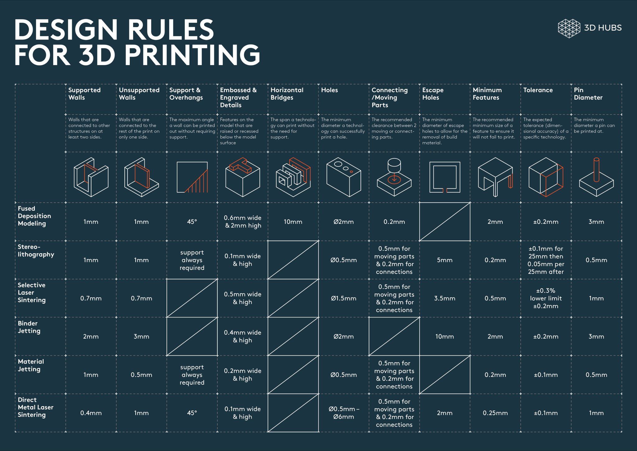
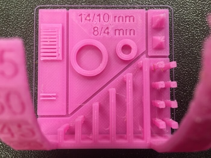
By the way, the measurements given in this chart are just general tips for when designing, they are not specifically identifying the limits of any one printer or printer brand. In my group, we tested design rules on one of the Prusa i3 MK3, using this test print from Thingyverse, by Marián Trpkoš. This print tests wall thickness/tolerance, angles, overhangs, bridging, dimensions, sharp corners, and stringing.
Our Results
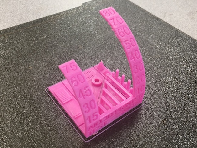
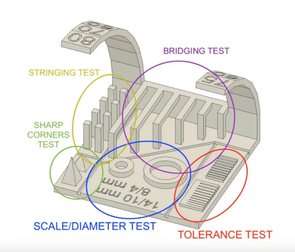
We found that our printer was capable of doing all of the overhangs and bridging, but the quality deteriorated around the 50º angle, for the overhang, and 20 mm stretches for the bridging.
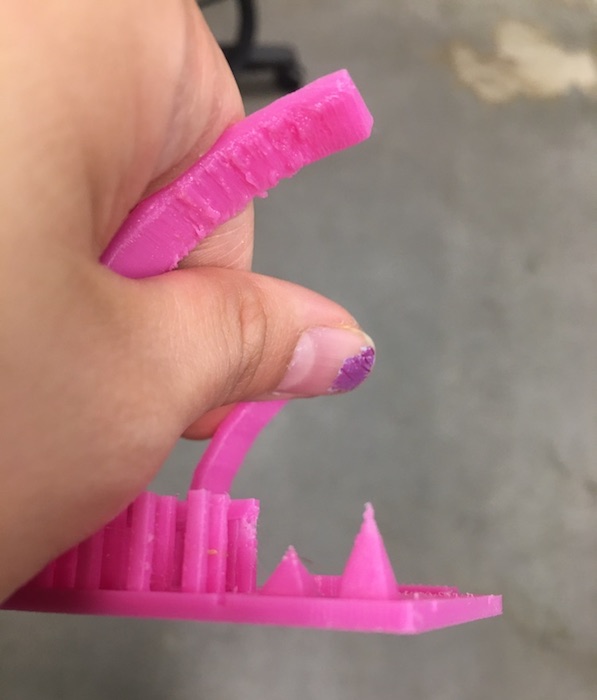
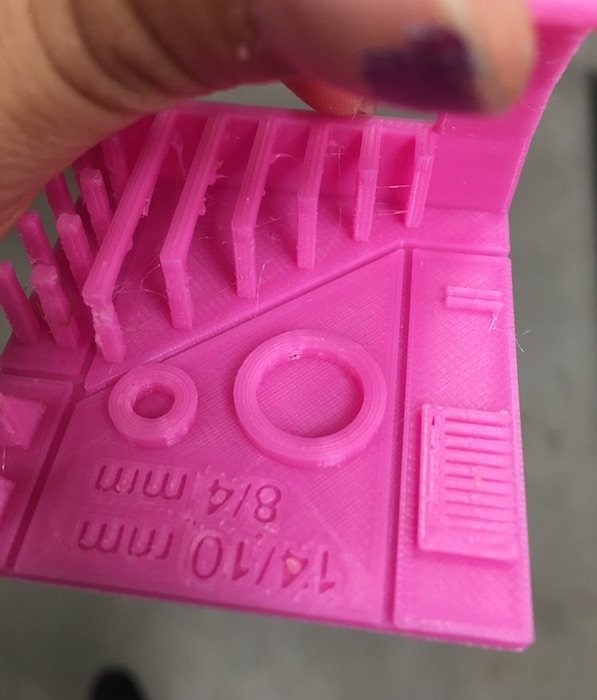
The stringing was there, but it wasn't too bad. Also, the printer wasn't able to do extremely very fine detail, as seen with the sharp pyramid test and tolerance line tests. In the line tests, the walls were able to get up to .1 mm close together, but it couldn’t print any lines .4 mm or smaller (which makes sense since we were using a .4 mm nozzle). The circles were part of a measurements test to see how close the designed dimensions were to the actual printed ones. It turns out this was pretty close: the large circle was actually 13.89/9.94 mm (outside/inside diameter) and the small circle was 7.85/3.95 mm.
Overall, this test print came out very well, and more importantly it can give us a good reference point as to what this Prusa printer's capabilities and limitations are for the design rules. Generally, as long as you're not printing in mid-air or have extremely thin walls, a design will usually work. These things are easy to work around by simply drawing the model a certain way.
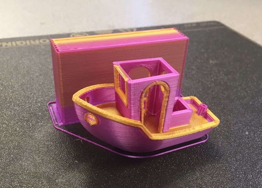
In addition, we tried making a 3D Benchy model on a multi-color printer. We got almost all the way through before there was an error in a filament change. This is a common issue we've been having, but given that this is probably the most complicated print we've attempted with this machine so far, I consider it a success! Up until then, the print quality was very good, with just a tiny bit of clumpiness around the yellow part of the archways.
3D Design and Print
The next part of this assignment was to design and print something that cannot be easily made using a subtractive method. This brings up the question, why choose 3D printing in the first place? What are the advantages and disadvantages of additive manufacturing with 3D printers?
What makes additive manufacturing special?
In terms of design, 3D printers are very good at creating many complex forms cheaply and relatively fast. This makes it a popular method of rapid prototyping. Printers can make complicated forms with interior spaces, because it builds the object from the bottom up. Also, printers are less wasteful since you aren't discarding lots of subtracted material. However, as mentioned before, 3D printers are not great at making objects with overhangs, and the detail of designs are limited by nozzle size and layer height. Plus, large, flat forms tend to warp given the plastic material and the heat, so it's better at doing three dimensional forms.
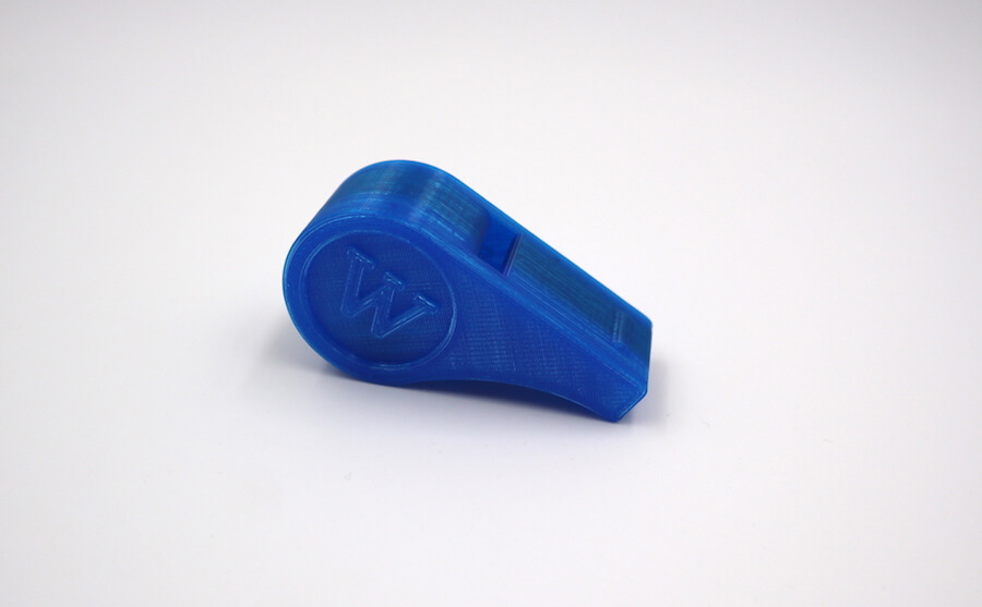
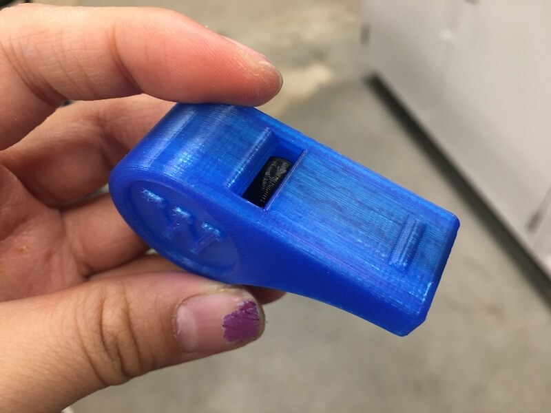
To take advantage of the properties of 3D printing, I made an object that could not be made in a subtractive method (like CNC routing or milling). I made a whistle, and this qualifies because the hollow space, and the ball inside of a whistle, cannot be carved or milled from one solid material. There are angles inside the whistle that an end mill, even a small one, could not reach given the size and placement of the two openings. Not to mention how it would carve a whole sphere inside of that hollow space.
CAD Modeling
Here I am designing the whistle in Fusion 360.
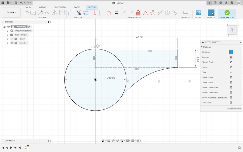
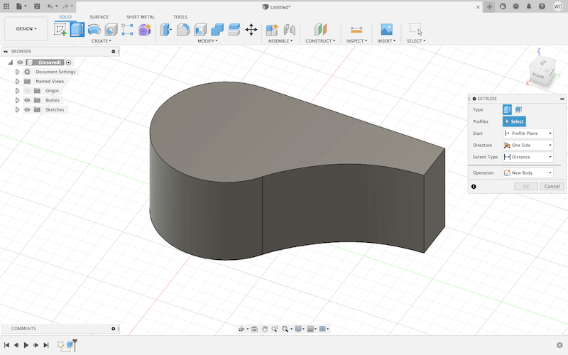
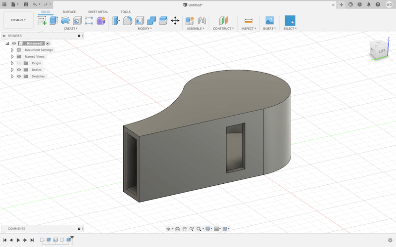
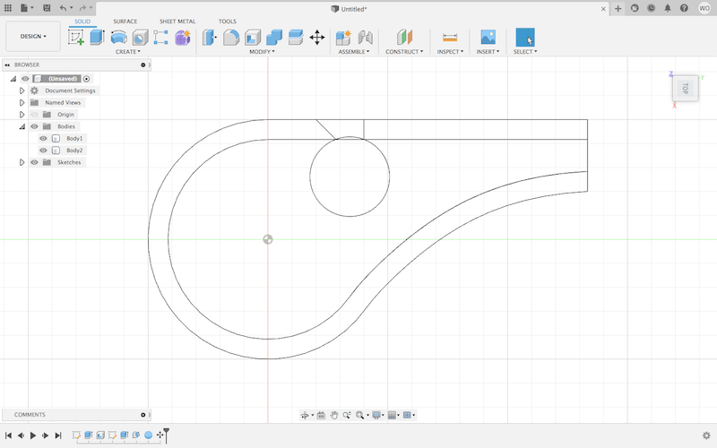
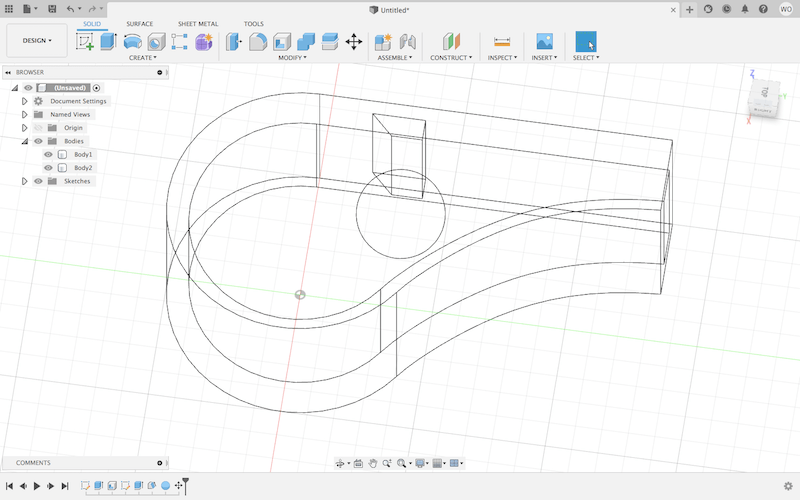
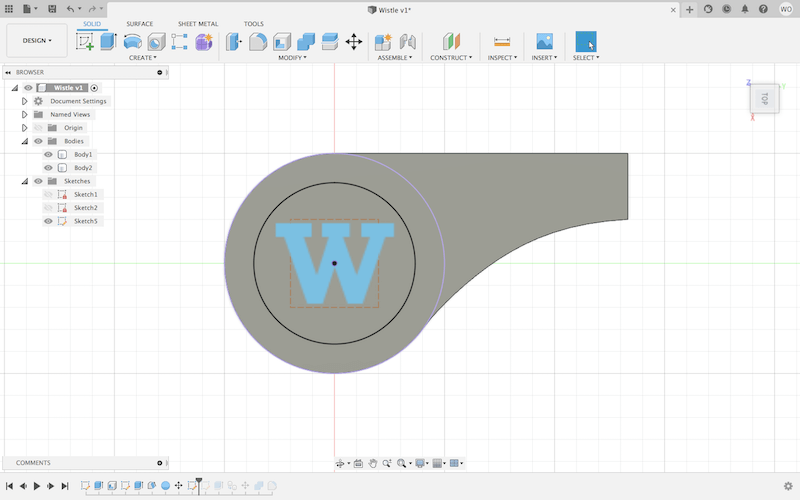
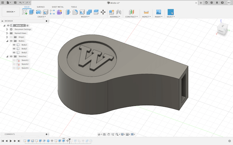
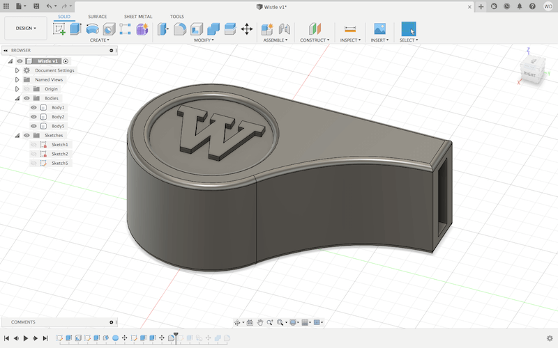
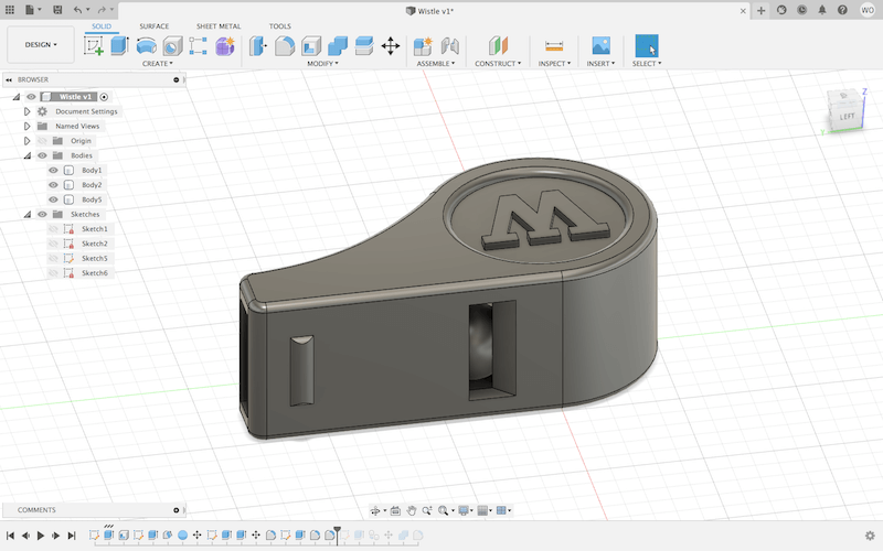
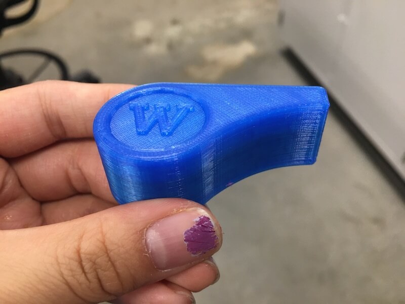
I sketched the general outline and extruded that. Then, I used the shell feature to hollow out the inside, and I added an additional hole for the air to escape from. Under "Create", I made a sphere which I positioned near one of the openings inside of the whistle. This sphere was just barely touching the sides and bottom to make it securely attached to something while printing, but able to be poked loose when it was done. I also added my initial for fun.
STL to G-code
Once I had exported my design as an STL file, I used a program called PrusaSlicer to prepare the model for 3D printing. PrusaSlicer is an open-source CAM software that "slices" a 3D model into layers which are then converted into g-code, which ultimately directs the printer.
To set up my print, I chose the layer height, infill, and PLA filament. It didn't have overhangs or significant bridging, so I didn't need any supports. Also, I used a Prusa i3 MK3 MMU2 printer, which is able to use up to five different filaments. My idea was to use a translucent filament for the main body, and another color for the ball so that I could see inside.
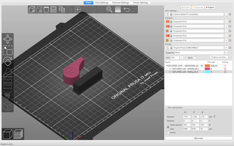
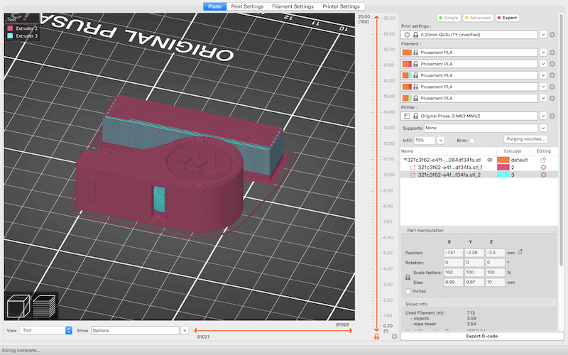
I used the "split to parts' function to separate the model and assigned an extruder to each part, in the menu on the left. Once I fixed my settings, I clicked "Slice now" and that brought me to the layer mode where I could inspect my print at every stage.
Finally, I exported the g-code to an SD card which I inserted into the printer.
3D Printing
With the multi-color printing, you have to pre-load both filament colors to the MMU2 unit. After that, I could go to "Print from SD".
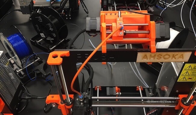
Then, the machine heats up the bed and nozzle to the temperature needed for PLA. Sometimes at this point I apply glue to help with bed adhesion. After that, the machine self-calibrates and starts the print.
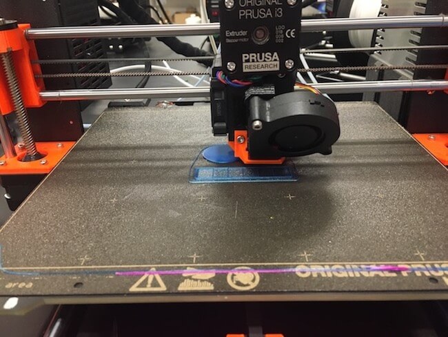
When it finished, I took the magnetic build plate off the bed to remove my print. Notice the block printed next to the whistle, that's the wipe tower that multi-color prints make to clean the nozzle in between filament changes.
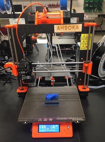
Here is my finished print!
3D Scanning
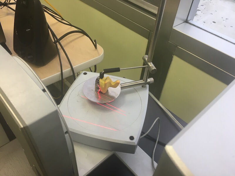
This week, I also scanned an object with a NextEngine 3D Scanner. This desktop scanner uses laser triangulation technology, where a camera and an array of lasers are paired together to measure depth and record color.
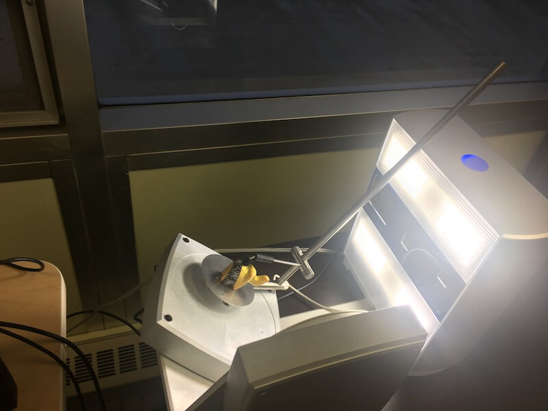
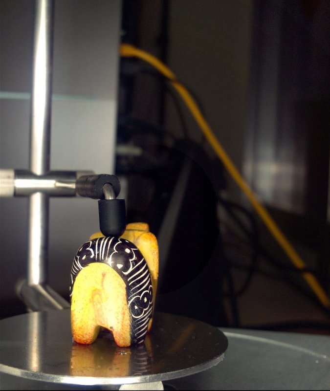
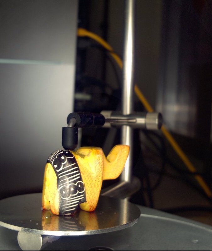
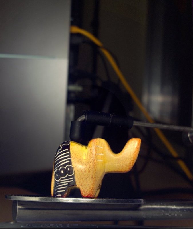
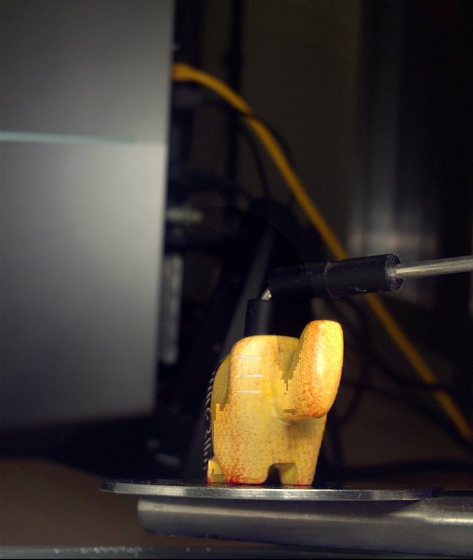
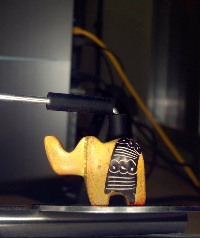
To set up the scanner, I secured my object using the metal gripping arm.
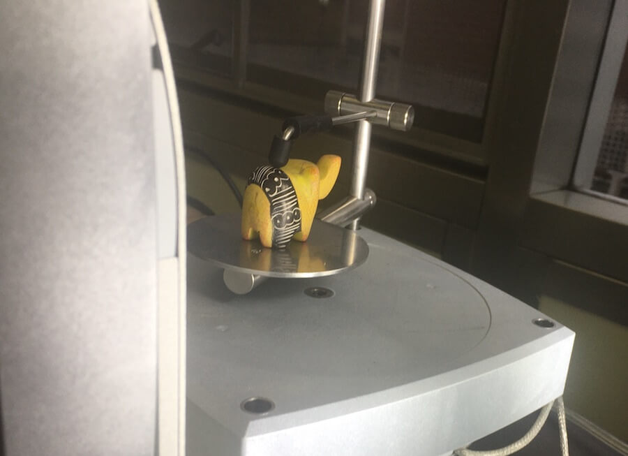
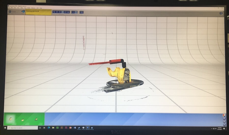
Then, I used NextEngine's ScanStudio software to operate the scanner, and later to convert the data into a 3D model. This scanner captures all of the sides of an object by rotating and tilting the mount. In the settings, I can create a "scan family" which are groups of photos/laser scans that are taken at the same vertical angle. I set up three of these; one with a high angle, low angle, and straight on.
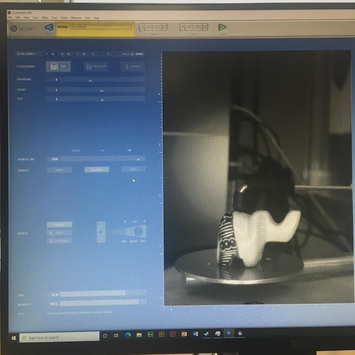
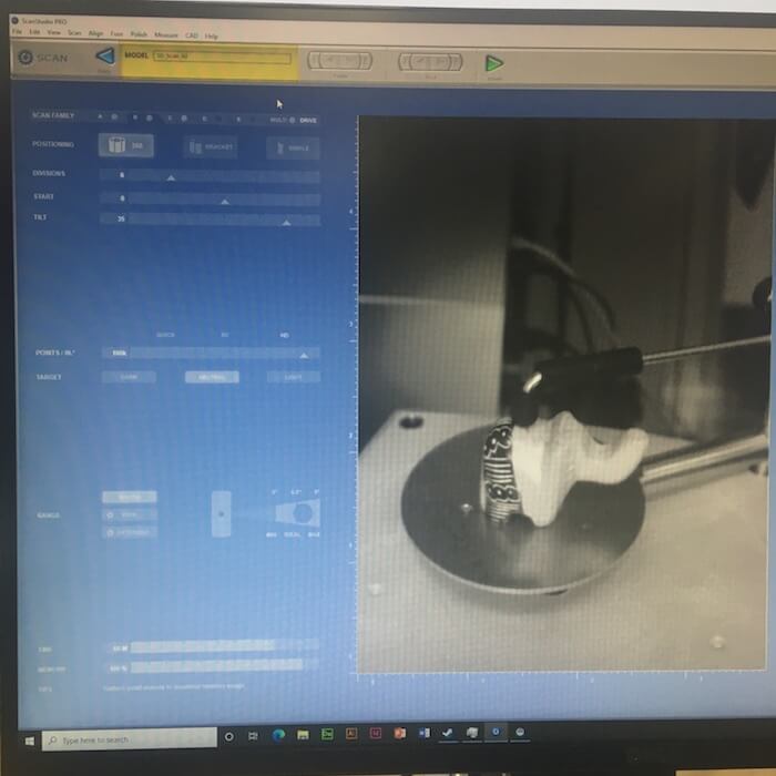
I set the positioning to be 360º, with 6 divisions, so it would fully rotate, while stopping to make scans 6 times. So, basically the machine begins scanning straight on, and the plate rotates to 6 different angles to make additional scans. Then, it repeats this at a high angle, which I've set to 35º, and a low angle, -15º.
The software estimates how long the scan will take, 68 minutes. I pressed the green scan button to begin.
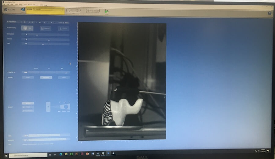
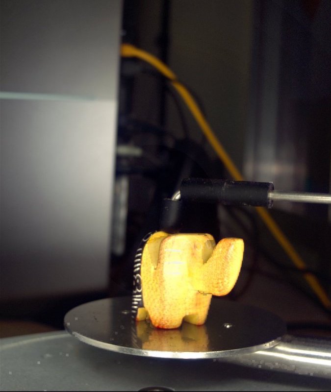
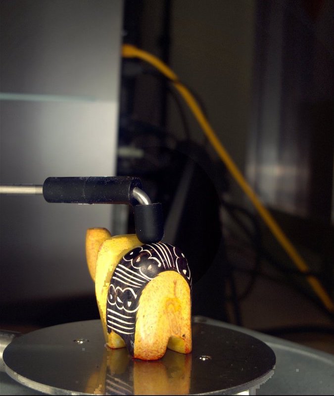
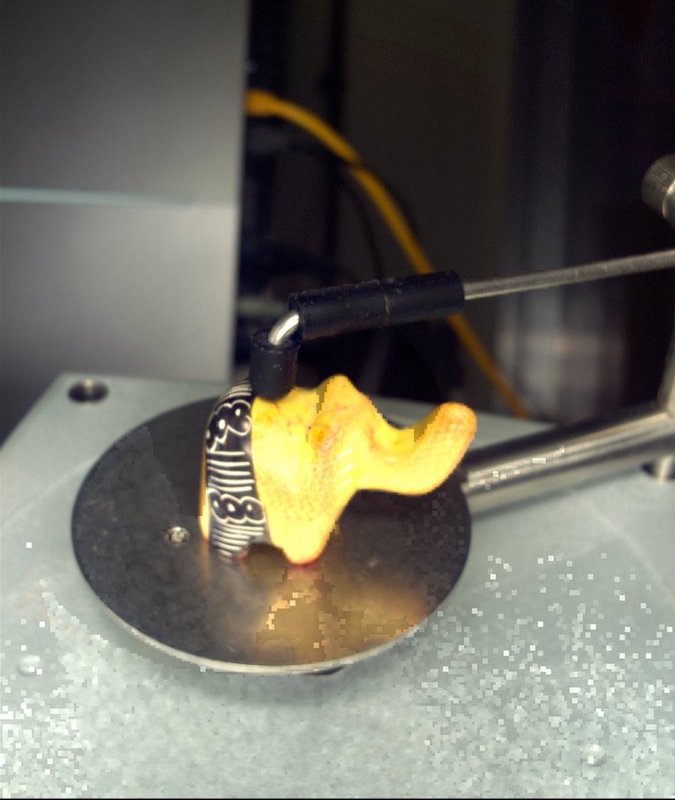
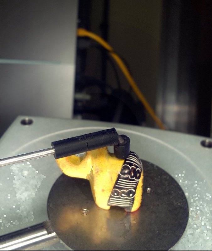
These are some photos taken by the scanner itself.
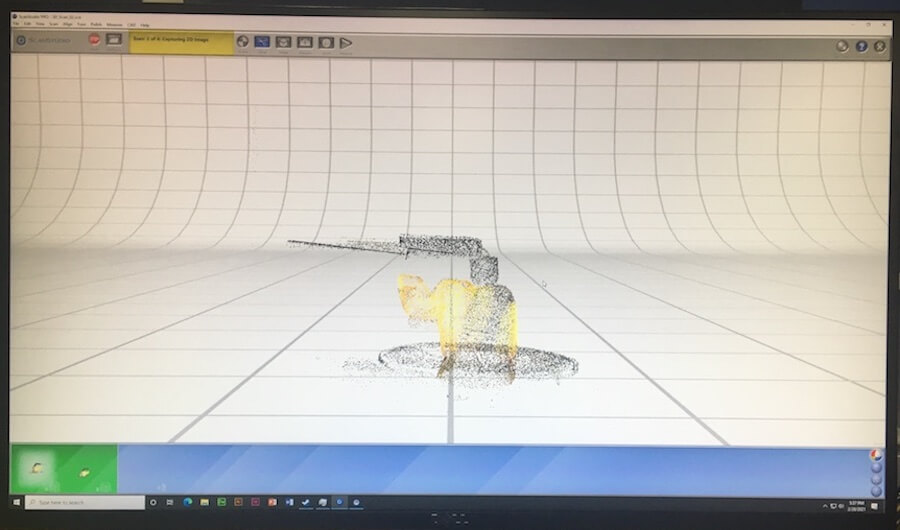
While this was going on, a point cloud was being generated in real time on the software.
When the scanning finished, I trimmed the data points to remove the parts of the scan I didn't want. This to whole process took a very long time because the software had to make a backup file, and re-align, every time I made a cut.
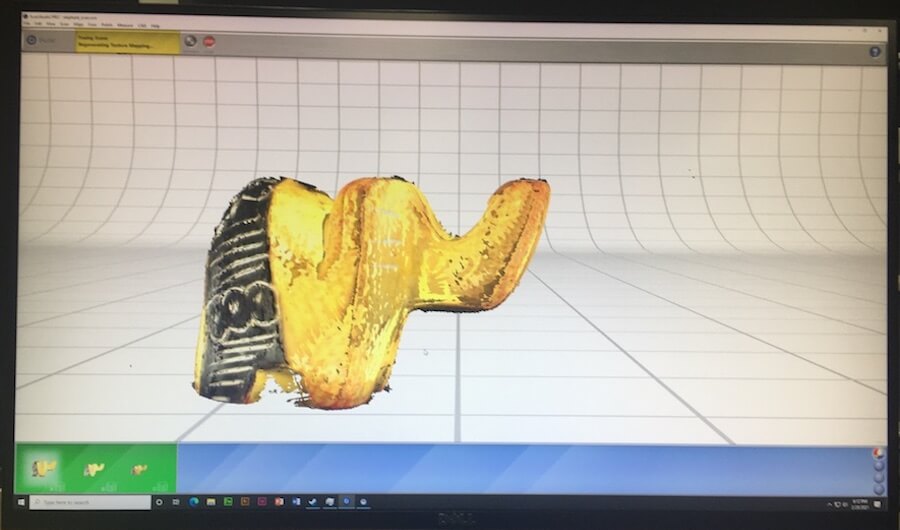
After trimming the point cloud, I fused the data from the three scan families together, making a mesh. Then, I exported this scan as an STL file.
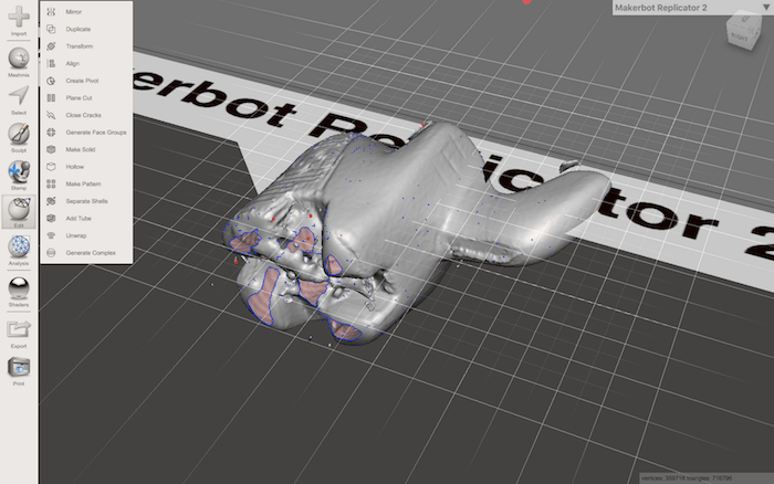
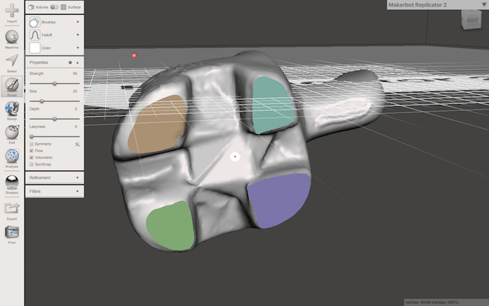
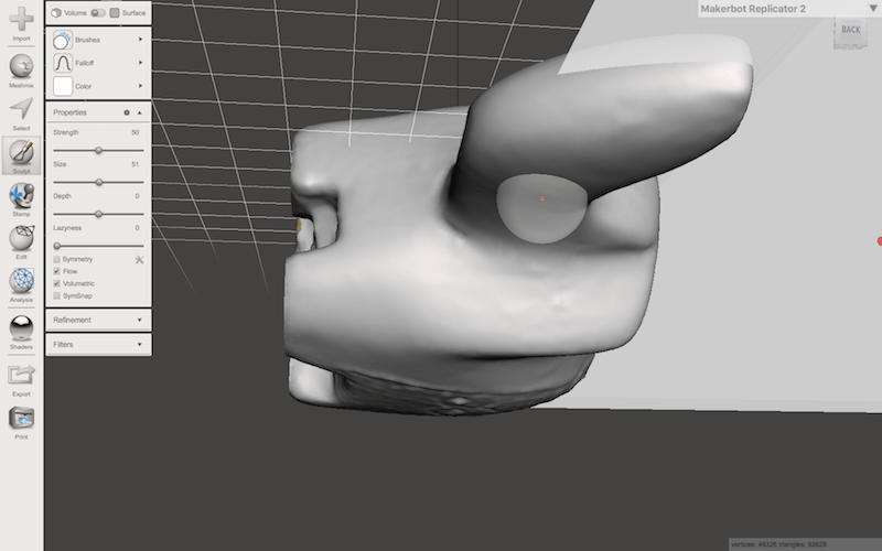
Meshmixer
The exported model still was a little messy, especially around the bottom, so I brought it into a AudoDesk's Meshmixer to tweak the model, by removing excess scan bits, and closing and smoothing the mesh.
Resources
- Test Prints from Thingyverse: *MICRO* All In One 3D printer test 3D Benchy
- Key design considerations for 3D printing | How to print better – How to design better
- Prusa 3D Printers
- NextEngine 3D Scanner Ultra HD & ScanStudio software
- About Laser Triangulation
Design Files
Updated: March 3, 2021