Week7; Computer controlled Machining
This week is a fun week, 'make something big'. Henk got us all plywood boards and we are supposed to make a design that will be human-sized and fit on one board. The design has to be prepared and milled on the Shop-bot-machine
Wednesday Global Class
CNC-Milling, workflow, Safety, possibilities materials and tools.
Weekly Assignment
Group assignment:
- Do a Lab-safety training and Test the workflow and specifications of the machine Individual assignments:
- design, mill and assemble something big
Planning this week
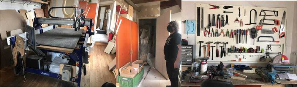
Due to Corona, we have to split up the group in halves to work in the Waag, I am scheduled to be there on thursday (instruction and group assignment) and because only one person can work on the shopbor machine at one time we made a schedule were everyone gets half a day to mill. My time was on saturday-afternoon. This week it is a very tight schedule. I made my planning around this schedule.
| Day | Lesson | subject/activity | activities |
|---|---|---|---|
| Wednesday | global class | make this plan | |
| Thursday | local class explanation of the Shopbot | group assignment safety | group assignment workflow |
| Friday | All day design and build the model in 3D | keep going | get it finished and exported as DFX |
| Saturday | prepare for milling | work the shopbot | Opentime I had to skip...(although I showed my just finished work) |
| Sunday | pick up the model in Amsterdam | sanding | family-time |
| Monday | work | varnish the wood | |
| Tuesday | work | assemble/make hero shot | Documentation |
| Wednesday | presentations | ready to present | fix last things |
Shopbot safety instruction
The CNC machine is the most dangerous machine at the Waag. This machine can really hurt people. Turning parts, chips of material can fly of, and the machine itself has strong motors that won't stop moving
Clean and organized working
One person can operate the machine, it is not allowed to do it together. If there is a second person in the room he/she has to stay away from the machine.
- Take care of an organized workspace. there is noting on the machine-bed except the wood that is to be milled.
- Also check around the machine are there not any pieces of wood in the way.
- Don’t touch the machine when it is on. Not on the board, not on the rails or any other place
Be Zen
- in order to operate the machine, take your time and stay calm. most mistakes are made when people are in a hurry and forget crucial steps in the workflow.
- don't start a job when you are in ar hurry (end of the afternoon)
Fire hazard
Next to moving parts there is also a fire-hazard. there are two dangerous situations:
- When the mill hits a screw and hot metal chips are sucked into the dust collector.
- The spindle keeps moving when you pause the machine. This will result in heated wood at the turningpoint and that is a perfect way to make a fire. So when you stop the machine, lift the Z-axis.
When hot chips are sucked towards the dust-collector:
- turn off everything (machine/dustcollector)
- loosen the dust-collector-bag and close it at the top, so no extra oxygen can get into it. Move the closed bag as quickly as possible out of the building.
- In case of flames, through it out of the window.
- In case of smouldering bits and pieces walk with the bag through the main entrance outside.
- If needed There is a fire extinguisher in the direct surrounding of the dust-collector.
Emergency exit
Take note of the emergency exit. Where is it, how does it open, where does it lead.
Personal safety
Take care of yourself
- No loose ends on your clothes (cords, scarfs, shoelaces)
- No loose hair
- Use safety glasses to protect your eyes (or your own glasses)
- Use earplugs/headphones to protect your ears
Group assignment workflow
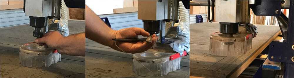
For the group assignment we used the design of last years group. that way we milled a pocket, and some finger-connections in a square and we can see if all the settings on the machine are okay.
Workflow for the CNC-machine
Design
for the milling you need a design, V-carve can import several different filetypes. The ones we checked were:
- .EPS (language2) (from illustrator to V-carve)
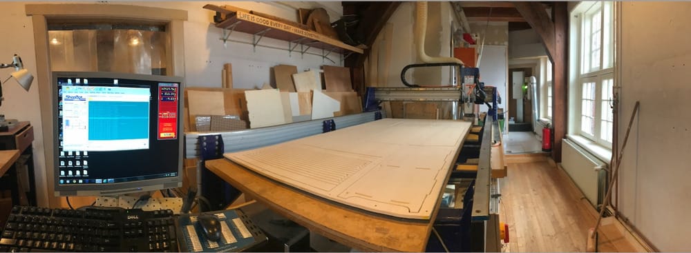
- .DXF (from Fusion360 to v-carve) It is good to know that the shopbot works 'landscape' the x-axis (alongside the window) is 244cm long and the Y-axis is 122cm long
Machinepreparation
- Find the right millingbit, (1 flat-end 2 flute, 2 ball-end, 3 flat-end-one-flute 4 the big boy to mill the sacrificial board) in our case we use a two-flute-flat-end 5mm millbit.
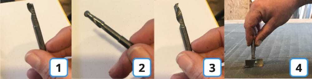
- Fit it into the matching collit and place it in the nut.
- See that it fits in the right way it should at least be 2 cm in the collit and stick out at least a few mm more than the materialthickness.
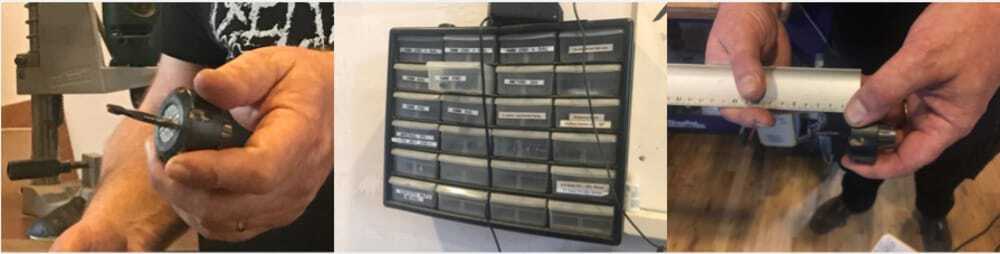
- Lower the dustskirt, with the wingnut at the back, so the spindle is reachable.
- Turn the nut-collit-millingbit combination on the spindle. Measure with the digital calliper if the millingbit is aligned at the right height.
- Use the two wrenges to fixate the nut. It should be with quite some force, but you have to be able to loosen it at the end of the job.
- adjust the dust-skirt to the right height and fix well with the wingnut. (if not, it will lower during the job and break, or ruin your work)
Materialpreparation
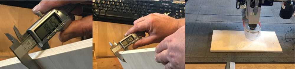
- Measure the thickness of the material.
- If it is a big plate, move the spindle back a bit and a little higher (see shopbot-part)
- Vacuum the sacrificial layer and check if there are no screws sticking up.
- Put the material in the desired position on the bed. (make sure the x and Y direction are equal to the design.)
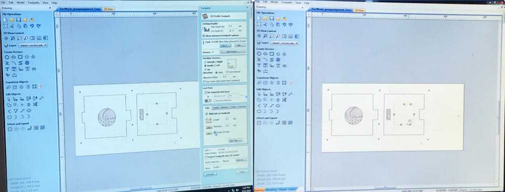
V-carve (dogbones, toolpaths, millsettings)
In V-carve all the vectors are imported in one layer.
- When importing a file V-carve wants to know the job-size.
- In the X and Y direction that comes form your design. (handy to put a rectangle around your design of which you'll know the exact size)
- In the Z-direction you have to measure the plate at several points and take the average of that to set the thickness.
- it wants to know the Datum-position (origin) marked as a red dot. Which is and should be at the bottom-left corner.
- The units are in mm, even though the size of an object can be quite big, it is still measured in mm.

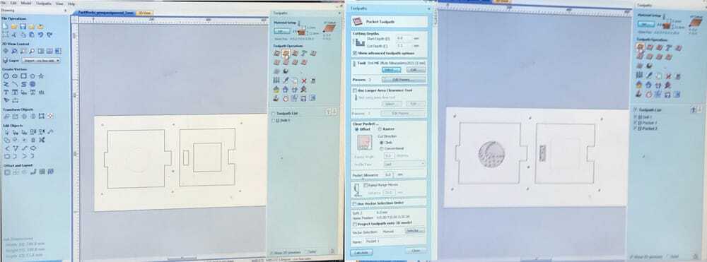
- Check the design and add dogbones or t-bones on the inside-corners, that way the connecting parts will fit.
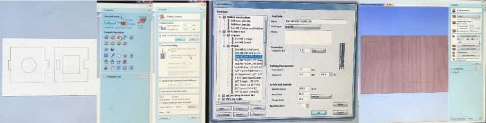
- While making the first toolpath you can also do the settings of the milling bit.
- (in our case 5mm two flute)
- the stepover is 60% and
- the pathdepth is conservative and half the milling bit size. (look at the amount of passes and depth to adjust this a little to the desired depth)
- the turningspeed of the spindle is 18.000
- Set the drillholes to fix the board to the sacrificial plate.
- start depth is 0.00, depth is (materialthickness- 6 mm). The drillholes are not all the way through. leave 1/3 of the board (or max 6 mmm.)
- The drillholes can be done with the same millingbit as the rest.
- There should be drillholes on the side of the board at around 30cm
- and in the middle of the board in places that it will fit.
- The drillhole-topolpath is the first to run, and since it only drills vertically the board won't move.
- pocket toolpaths.
- These are milled on the inside and go to a certain designed depth.
- If you have pockets at different depths you'll need seperate toolpaths.
- if there are pieces that have to be pressfit, the machine needs an offset of -0,3mm. Then the pieces will fit nicely. if you want it tight, then it should probably be -0.28.
- Profile toolpaths.
-
These are milled all the way through
-
For the outlines of the design choose mill on the outside,
-
For holes or windows choose mill on the inside.
-
Add tabs,
- the standard tabs are too small. especially if the thickness of the material is not quite even. It should be at least 5X5mm 3D.
- Add the tabs in convenient places. in the middle of a straight bit is nice, because it is easier to sand them off afterwards.
- V-curve puts them at dogboneholes and that is also a good idea, because then on one side of the board it is possible to only sand away the straight corner and have a nicer finish
-
Set the outine toolpath as very last, then the wood is still connected firmly to the board while doing all the different toolpaths.
At output toolpaths: 7. Save the drillingholetoolpath as a seperate file 8. Save the other toolpaths as a combined file (but check if the drillingholepath is not part of that.)
Running Shopbot
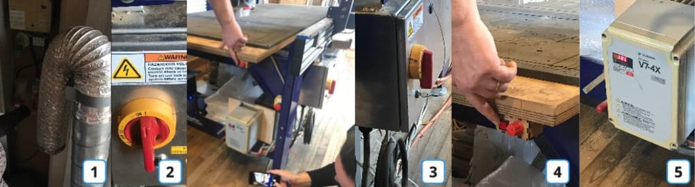
- First turn on the dustcollector in the far end of the room. |1| (don't turn on the vacuumpump yet)
- Turn on the shopbot with the big red knob. |2| (don't turn on the spindle yet) Now the machine is turned on and ready for calibration and preparation.
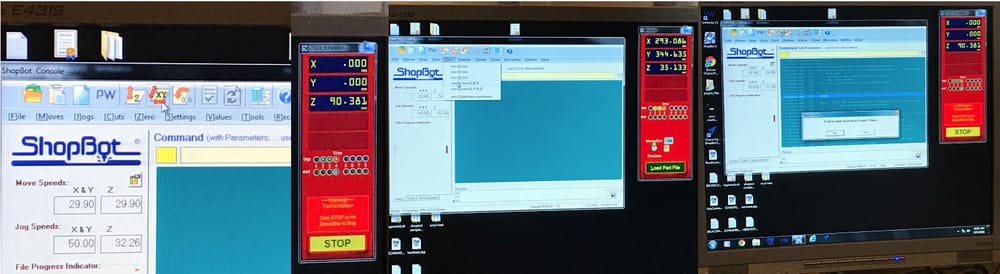
- Turn on the shopbot program on the computer.
- if you press |K| on the keypath the move-option is activated and it is possible to move the spindle around.
- the arrow-keys for X and Y
- |page-up| and |page-down| for the Z-axis.
- If the millingbit is connected correctly 'Zero the X-axis and Y-axis to machine'. The machine will take over and move to the real Zero.
- move the spindle to the lefthandcorner of the material with the keypath.
- Make a picture of the X and Y position. (so if you have to turn of everything you can move back to that spot)
- in the menu 'Zero' push Zero 2 axis X&Y. (the numbers in the machinesettings change to 0.000)
- Move the spindle a bit away from the corner (The corners are never in the right heigth)
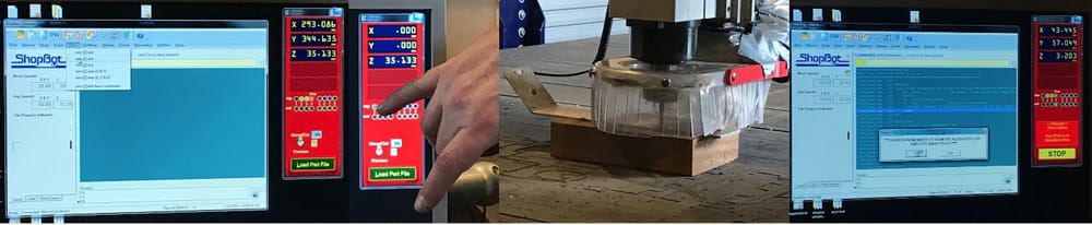
- Put the Z-leveler-tool nicely under the millingbit. (first chack if it is making a connection if you touch it.)
- push the z-leveling button. The machine takes over and will level in the Z-direction. (+3.203mm, because that is the thickness of the Z-leverler-tool)
- move the spindle up a bit with |page-up| and replace the Z-levelertool in its pocket on the side of the spindle.
running the job in the air
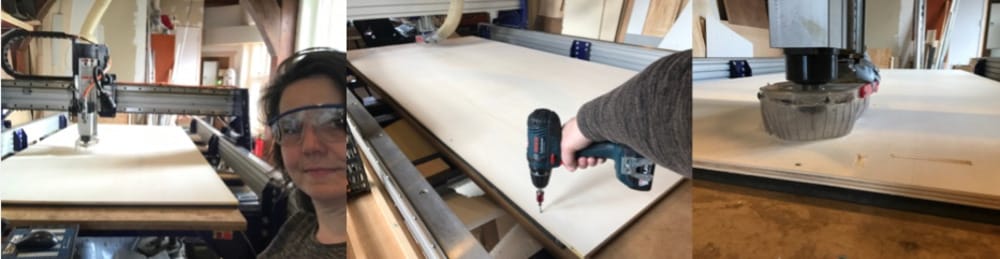
First put on the safety-gear (glasses, earprotection) and check if the millbed and the surroundings are clear.
- First measure the Z level a bit above the material on the bed, so you can check if the toolpath is okay.
- Load the file (file-partfile-load) A notepad with the file on it will appear on the screen.
- Turn on the dust-collector-vacuum-pump |4|
- Turn on the spindle (optional) |3|
- Set the spindlespeed to 18.000 |5|
- press start.
- keep your fingers at the spacebar, that way you can pause the machine
- if the job seems to do fine press space and exit the job.
running the job
First put on the safety-gear (glasses, earprotection) and check if the millbed and the surroundings are clear. This is a good moment to have some coffee or a toiletbreak. Because you are due to sit in the control-position during the whole job.
- level the z-axis at the material height.
- Turn on the dust-collector-vacuum-pump
- Turn on the spindle
- Set the spindlespeed to 18.000
- press start.
- Keep your fingers at the spacebar, that way you can pause the machine if something is wrong.
fixate material with woodies
The first job is always the drillholes. After that turn of the spindle and the vacuum. Screw the woodies into the board and sacrificial board to fixate the material. You can move around the machine to do that and if it is out of reach, you can even climb on the machine . Push the material down while attaching, that way the board is as leveled as can be.
End of the job
At the end of the job:
- move the spindle to a desired position.
- turn off everything
- unscrew the board
- remove the whole board or the parts
- clean up all the wood and dust with the vacuumcleaner.
Individual assignments
Design, mill and assemble something that is big
Inspiration: I did not have a lot of time, but this assignment is something I really love.
- I love to think out something that will fit on the board but is about as large as can be.
- I want to try out bending wood in a way, 'curving' would be a good possibility. While researching I found out that it is in fact Kerfing (from the circlesaw-blade-kerf)
- I was thinking about a bicycle, a chair (folding), a housing for my chicken, a lounge-set for my daughters lounge-attic a little bookcase that can replace the old one in my front-yard and a little greenhouse.
- I was a bit afraid that all my ideas were too complicated, but the greenhouse is something I really like, because, in the shops, I don't seem to find something that suits my needs.
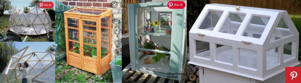
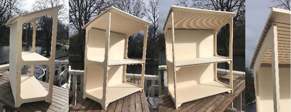
Online I found different ways of making a small greenhouse. I really got inspired, but the size of the board of course was the maximum size. The 2 middle photo's are something I would like, especially the one made of plain wood.
I looked at different projects over the last years that did a small greenhouse in the big-thing assignment and found 2 interesting ones. A german student who made a nice modular design, but with a very ugly plastic cover Tobias made a nice hous-shape with puzzelpiece-connections under 60 degree corners
Friday (a very long day)
So I started drawing and came to nice idea that I could make spirally and if it is too much milling for the time I have, I can mill it without the windows and it it can be a bookcase. (for in the front yard)
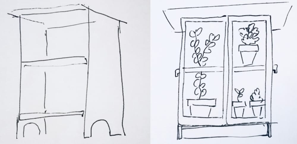
Spiral 1
I decided that my greenhouse would have 2 shelves and a plant height of 40 cm and 6 of my favorite square pot-saucers should fit, so I can put all my small growing seedlings in there. Made some sketches to find out global measurements.
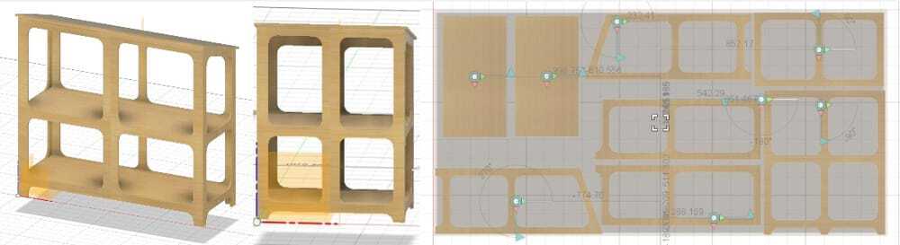
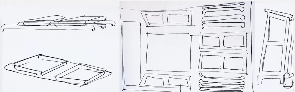 I made a first try in Fusion in order to find the right size. I found quickly that my idea was a bit ambitious for the board-size. It was way to big with the 3 square saucers in it, so I changed it to 2 saucers. That was easy because I build my parameters around the saucer-measurements. I thought of idea's where I did not make sides nut used ribs in the corner.
The model was finished enough to try and get the parts in a board.
I made a first try in Fusion in order to find the right size. I found quickly that my idea was a bit ambitious for the board-size. It was way to big with the 3 square saucers in it, so I changed it to 2 saucers. That was easy because I build my parameters around the saucer-measurements. I thought of idea's where I did not make sides nut used ribs in the corner.
The model was finished enough to try and get the parts in a board.
I found a great tutorial on how to make a bookshelve on a shopbot with fusion360 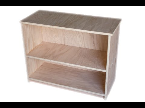
and it helped me a lot by setting up the board and the way to connect the different parts by making planar joints. that way it is possible to have some freedom doing the nesting of the parts.
It did not have the connections yet. But for measurements it was fine. When I made it this way, it would barely fit on the board and I had to lower the foot of the greenhouse a few centimeters to get the extra space.
Spiral 2
So now I had to make a redesign with something Kerfed in it. Back to drawing on a sheet of paper.
We decided here at home that the Kerfed roof would be the best option.
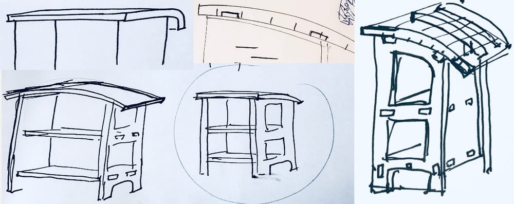 So now I had to study Kerving. I found that it is named after the sawblade of a circle-saw and that there is quite some information online. I found a Kerf-calculator and a niceI wanted my board to slightly curve and have a big radius.
Adrian Torres, from fablab Leon did a nice table with kerfed corners and he tested kerfing plywood for that.
So now I had to study Kerving. I found that it is named after the sawblade of a circle-saw and that there is quite some information online. I found a Kerf-calculator and a niceI wanted my board to slightly curve and have a big radius.
Adrian Torres, from fablab Leon did a nice table with kerfed corners and he tested kerfing plywood for that.
Testing Kerfing
The information everywhere said that I had to do my own kerf-test, for how much wood should be left over. This is because all materials are different. I thought it was impossible to go to Amsterdam, It would take too long and the other half of the group was there getting instrucions. But since Kerfing is based on the Kerf of a sawblade I decided I could do my own test at home. It was raining badly, so I did my sawing in the shed. I found 2 pieces of 12 mm plywood and tried different Kerf-depths and distances between the Kerfs.
I found that 2,5 cm as a distance was doing fine and 3,5 mm is the best thickness, a bit bendable but wont crack the wood.
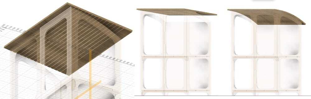
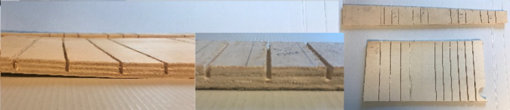 With this I had enough information to redesign my model. The maximum front height and back height would stay the same, but the roof would be kerfed.
Redesign in Fusion360
Sadly enough, in my design in fusion was not easy to change only the roof. All kind of parametric things were dependent on it. Therefore I decided to make a new model, only using the parameters and the first sketch.
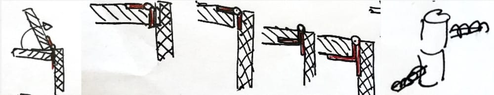
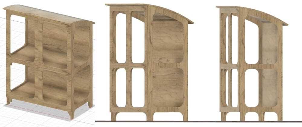 The shelves and other inside parts would have pockets to connect to the sides and back and the sides and back would connect with box-joints,
The shelves would not have enough strength to hold all my plants so I made a small vertical board under it. And by letting that slide inside a pocket of 6mm in the shelve it would be constrained for bending sideways.

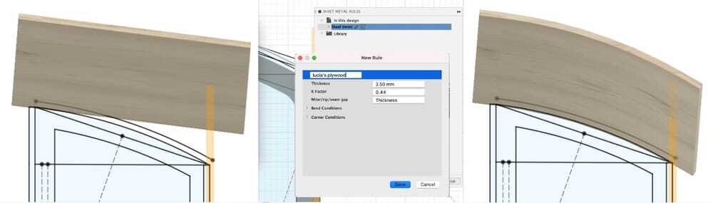
The kerfed wood was complicated to make in Fusion, but I found a tutorial using metal sheets, the guy in the tutorial is playing around a bit and not very sure of how to do it, but at least it gave me a good idea how to make my Kerfed wood.
Exporting straight to Shopbot.
Since V-carve is not available for Mac, I have to think about a way around that. And my milling time is already on saturadyafternoon and want as much time possible to actually mill. So with the thursday-group we thought we might skip v-carve altogether and export from fusion to shopbot straight. Henk sent some nice things about the manufacturing-part in fusion to us al, so I will dive into that.
With manufactiuring in fusion this would also be possible
I found a nice overview of how to do it 
and I found the explanation of last years class of Ferdi in camp lintfort on how they do it. I watched it, but my design was not finished yet and I was planning to follow that later on.

Dogbones
But first I needed to fit the dogbones/T-bones in my design or the parts would not fit. The dogbone diameter is the same as the milling-bit. So 5mm in our case There is a great dogbone-inserting tool for Fusion360,
It has some bugs, I was doing everything at 23.00 PM and that is not the best time to figure out where the libraries are. The mistake with the capital instead of the lower-case was helpful and put the dogbones on 'static' instead of parametric.
Sheet metal flat
I could not get my curved board on the main board.
The sheet metal has a different way of exporting through a flat pattern. But then it would be a different file. I solved it by redrawing a solid shape and using a project part onto sketch to construct it with the right measurements. (Probably not parametric anymore, but I need to solve this baby to be able to finish this spiral)
The real export
On fridaynight Henk told us that we have to use V-carve. That was a setback, because I did not look into the possibilities of importing into V-carve and there is no mac-version, so I cannot test it. Probably they talked about this on the fridaygroup. Philip shared that it is possible to import Illustrator-files into v-carve. But since it is an older version the .EPS-file had to be CS 2 version. I did not know what that was, but i'll find out.
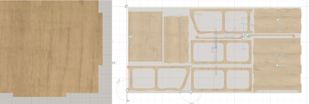
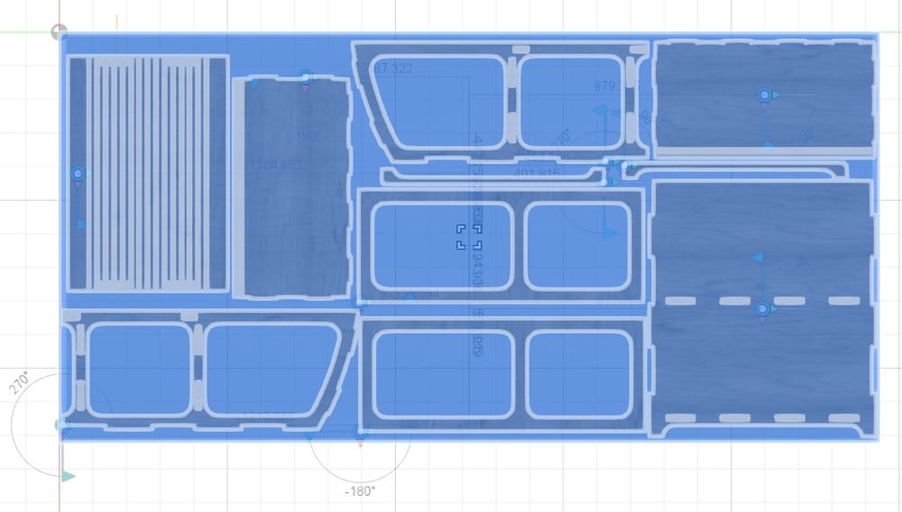
I placed all my parts of the new design on one board and made 1 sketch projecting all the parts in it. That sketch I exported as .DXF.
Saturday
I imported the .dxf into illustrator,
- all the lines are seperated and turned into particles. I decided to split the different toolpaths in different layers to get a better overview. Since there wer a lot of particles it was quite a manual job to select al the right bits to clean everything up.
- I found a few tiny mistakes, dogbones in weird places. So in order to be able to make toolpaths I connected all the little bits.
- Since I am Kerfing and therfore my lines are overlapping the roof was quite a mess in illustrator. Now I knew the measurements so I did my fourth redraw of the roof.
- I adjusted the artboard so I have the X-axis and Y-axis in the right direction
- I added drillholes (about 30 cm apart on the outside of the board and where it fits inbetween the parts And I exported the file as EPS. I could not find the setting Philip said. But in the ‘save as EPS popup’ I could find language 2 or 3 selector, so I chose 2
The boards are 1.22 meter by 2.50 meter, that is actually bigger than we thought, so it would probably have fit with the whole foot, but it is too late to change it. By the way, the sacrificial board is only 244cm so the screwholes can not be all the way at the end.
And now I am as prepared as can be and waiting for the moment that Philip's design is all milled and ready.
The Milling.
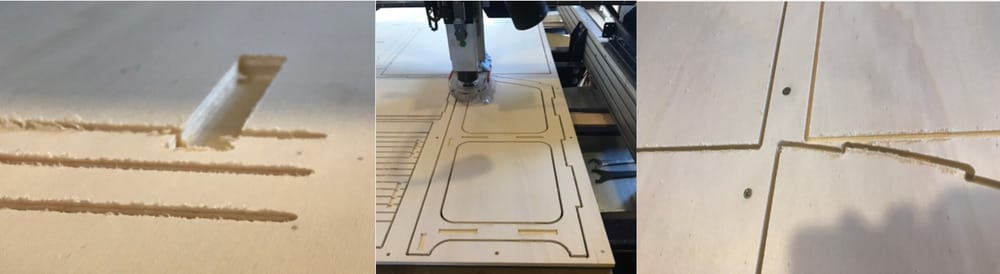
I imported the Illustratorfile in v-carve but the measurements were off. I thought I put everything to mm, but then illustrator makes it into pixels anyway. Philip said that the way around this is to change the units to mm in the main preferences of illustrator. I did that and my design was very small in illustrator, but luckily I had my board also in the drawing and knew the exact measurement ot that and could scale everything nicely. Then I exported it a second time. After that I followed the workflow that I wrote and made nice toolpaths in V-Carve. Changed the millingsettings to a depth of 3mm (that would be one pass less for every toolpath) V-carve really likes closed vectors, (no double lines) it will point them out (by refusing to calculate them). It is possible to find them in V-cave and change it there. But for next time, it might safe machine-time to do it in illustrator. After the parts that did not fit on thursday, Henk decided to test the offset that we would think that worked was -0.3mm tested that on friday and had som nicely fit parts laying around.(so the press fit-parts will actually fit) He showed me where I could change that in V-carve in the toolpath-tool to set that for the right outlines/pockets.
It was really nice and relaxing to work with only Henk around and I had a great afternoon setting it all up.
After an Air-run for the drillholes Henk said "go ahead" and I did some fine milling of the drillholes. And fixed the plate to the sacrificial board.
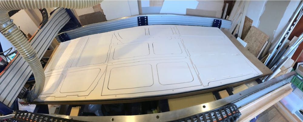
My design eventually took 1,5 hours of milling, it is amazing to look at.
 During Saturday-opentime I had my milling so I had the chance to wave at the people there and at the end show them my kerfed board.
Sunday
I drove by car to amsterdam to pick up all the pieces and showed my son Arend around at Waag.
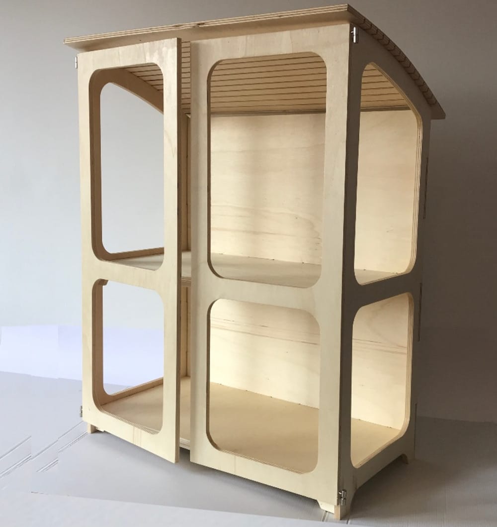
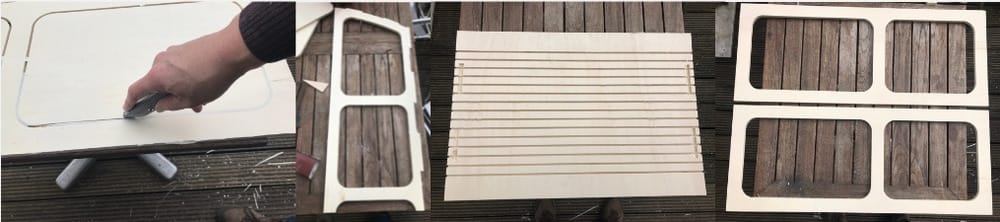 At home I cleaned up all the sides and sanded all the tabs. I could actually put everything nicely pressfit together. really nice.
 The roof is still pretty straight (it is bendable, but it wont stay in the curved shape) so I looked into steam bending to have a better fit of te roof. I build a nice round thing to bend it around and wetting the board and putting it in fornt of the heater in this bended position had to do the trick
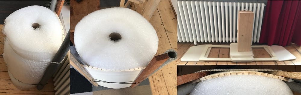 Also one of the sides and the door were a bit crouced, so I used the same method to straighten them.
Monday
Of course my greenhouse will stand outside, so I need to varnish all the parts, else it will be very ugly and loose by the end of the summer. SO I ordered some varnish. Because of the lockdown, the shops are only partly open, so I had to pre-order everything and wait 4 hours and then stand in line to get my order. It felt really eastern-european, back in the old days, hahaha
Mondaynight I varnished everything.
On tuesday I could fit it together for real. I looked into hinges and with some nice drill-in hinges it would fit nicely . Now the wood part is finished.
 for now I can cover the windows with plasitc sheet, but if I can find a way I would like to make some acrylic windows in it. (hopefully the lasercutter is repaired soon, then I can fit it perfecly in. )
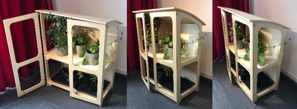
the result
Learnings this week
This week was really nice,
- It is a lot of work to get everything ready to mill. I could have made a better design if I had had more time beforehand and milled on monday.
- This week was weird, First I worked really hard, but on sunday I realy had time for my family and on monday I even found time to clean up my always crashing computer... (halfway there I hope)
- Putting the different outlines and pockets in different layers in illustrator was handy but V-carve doesn’t keep them.
- measuring the board is something I could have done before machine-time started.
- I made my tabs a bit small, (some of them broke when I wanted to lift the cut board.) 5x5 mm 3d would be better.
- I am happy with the result. More Spirals to come
- It is wonderful to see the machine make something I designed, and so very nice with perfectly curved shapes. Normally when I make somthing at home I am confined to my circlesaw and Jigsaw and that is never as perfect as this computer does the curves, I love it.
- If I have the chance I will try and do this again.
Extra Spirals I looked at
- I would lik to add (acrylic) windows in it, but then it would be nice to have a niece slot around the window that they would fit in. I thought of this, but that would again take more milling time and I only had 4 hours setiing up the machine and doing the job.
- I was planning not to use hinges in the design, but to mill them also form the wooden board. I found some nice examples of wooden hinges (with a metal pin inside) but it was too much time to make that on friday.
- the middle shelve should actually be 2 shelves so it is possible to only fit in 1 and have bigger plants grow on one side. I had to choose to make one shelve or 2 halves, I decided for now that One shelve fits on the board and would be more sturdy, but if there is a left-over piece of 12mm wood I would like to make an extra Half board and test it.
- the middel shelve does not really have to be a shelve, it could also be a raster or rims, that way sunlight couls come in everywhere where there are no plants.
Links to Design-files
here are the links to the designfiles of this week:
- kasjetotaalmm.eps or designfile-download
- Allesals1tekening1eversie.ai or designfile-download
- Allesals1tekening2.dxf or filename-download