Week 2; CAD, Computer Aided Design
Try out differnt 2D and 3D CAD-tools and find which ones work well for you. I decided to learn more about illustrator and work with different 3D-tools to learn the different workflows and basic possibilities
Weekly Assignment
In my own words
This week the assignment is simple, but therefore very broad:
Try different tools and make representations of your product for the final project with it. Raster/ Vector, 2D/3D. Image/Video.
Planning this week
| Day | Lesson | subject | activities |
|---|---|---|---|
| Wednesday | global class | make this plan | |
| Thursday | local class | Fusion 360 tutorial | opensCAD introduction |
| Friday | local open time | fusion 360 part 2 | |
| Saturday | global open time | build model in fusion 360 | look into illustrator |
| Sunday | regional course blender 3 | illustrator tutorials | work on Blender |
| Monday | local open time | Illustrator | documentation week 2 |
| Tuesday | local open time | work | render idea and screen |
| Wednesday | presentations | ready to present | fix last things |
Learning activities; Starting point and introduction to the subject
To start with I looked at the presentation and I found that I know some of the tools, I can barely use them though. I am a bit familiar with Photoshop, and way back I learned the very basics of 2d and 3D CAD tools. And although I do understand the idea behind vector-based images, I never worked with Illustrator and every time I try to make something the practice is very hard and I give up. So my main goals this week are:
- to be able to make a basic 3D-model in Fusion and in Blender
- and (very importantly) to work with Illustrator.
Blender first steps
I followed along with Ferdi (Camp Lintfort) on the Blender tutorial he is giving on sunday-evenings. This is really great. He has a very relaxed way of explaining, and we can follow along.
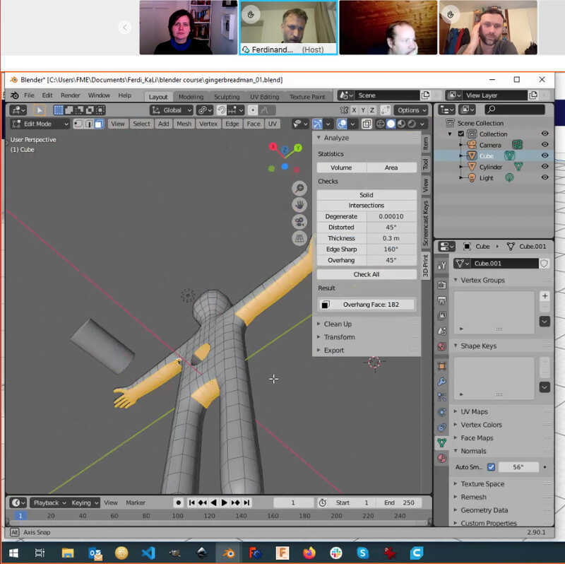 Next to this he writes down all the steps in the tutorial documentation, which is great because it is quite a hassle to listen to the instructions and explanation, doing it along and write in my notebook. I notice that sometimes when I missed a step I get completely lost and I really have to work along with the tutorial documentation.
Week 1
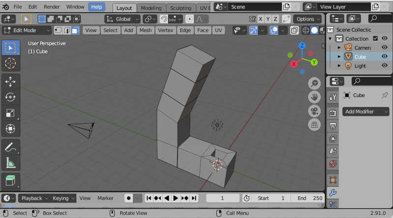
We learned the basics of setting up blender, moving around in the space and making our first constructions with different shapes and moving, rotating and scaling them. We also learned about Extruding.
 Week 2
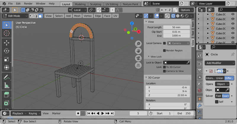
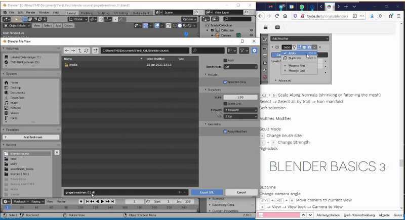
We worked on making a little gingerbreadman with boolean operations. and playing with the possibilities of the different ways of working with the shapes, sides, ribs and vertexes.
 Week 3
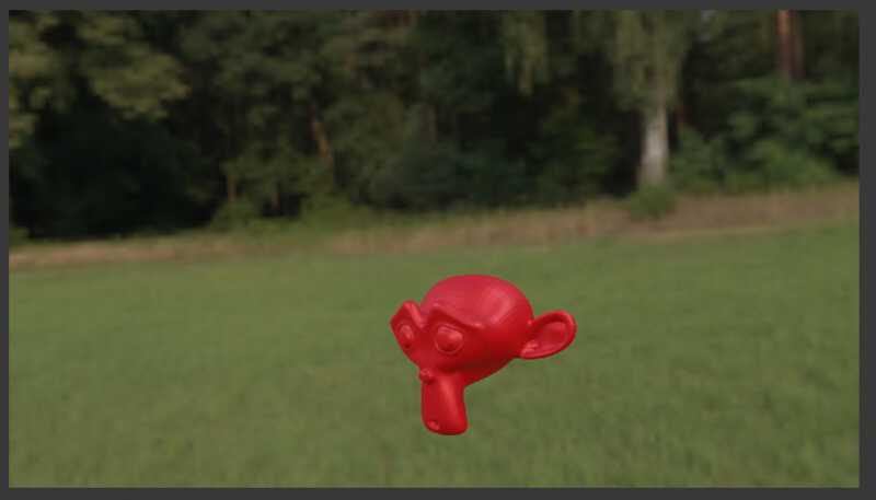
We were materializing the object, Exporting it as STL
 for 3D-printing, working with camera and light settings and Rendering. Nice to learn was to use a HDRI-file as a 3D surrounding, find them on hdrihaven
 The second half of the evening was focussed on things different people wanted to know, so we did a little with animating and particles.
Week 4
Next sunday, last lesson.
The second half of the evening was focussed on things different people wanted to know, so we did a little with animating and particles.
Week 4
Next sunday, last lesson.
Fusion360 first steps
My first problems were the installation of fusion. Because we started downloading all these tools during bootcamp-week before we had our licence with the FabAcademy. I had different licenses, a free trial account, I tried to sign up with my work, but was refused and the FabAcademy-version with a different e-mailadress) this confused me during the tutorials on thursday and friday. I was still stuck in the free trial while I should have joined the rest of the group.
- learning point: 'try and get the right version of a program while joining a tutorial'
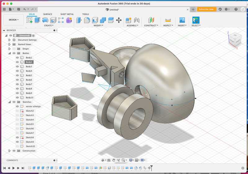
On Thursday we had a nice surprise, we could join in with the french group of Agrilab and Luc would give us an insight into fusion 360. it turned out to be a hands-on tutorial, which was great.
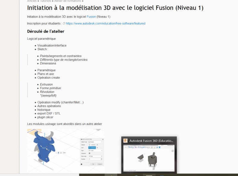
Luc showed us the basics of fusion. We worked making sketches in 2D, converting them to objects Extruding and do a lot of boolean operations with them. We ended up with a space full of shapes with ad-ons and hols in it.
Fridaymorning we had our second Fusion lesson with Michelle (Henks assistant at Waag) She prepared to make a pencil-box with us and it was a really nice follow-up, because this time we had a real model that we wanted to model in a parametric way.
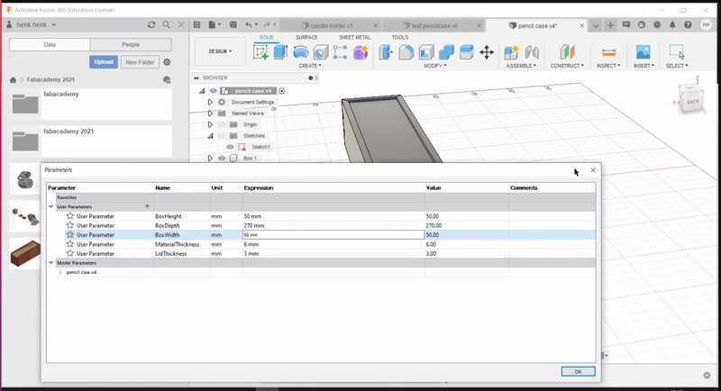
The lesson was quite fast and it was hard to keep up while looking at the explanation on the Jitsi/Zoom screen and meanwhile do the same action on my own screen. So a couple of times I stayed a bit behind but I ended up I making my own parametric box.
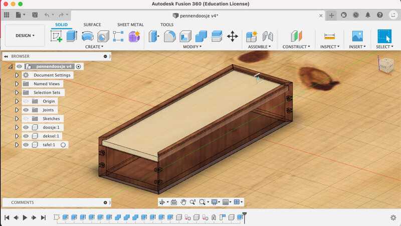 I especially had some extra work on getting the splines in the corners, they had to be evenly spaces and cut out from both sides, but meanwhile be materialized as wooden pieces. for this I eventually learned how to use the 'keep tool' tick-box in the boolean operation window.
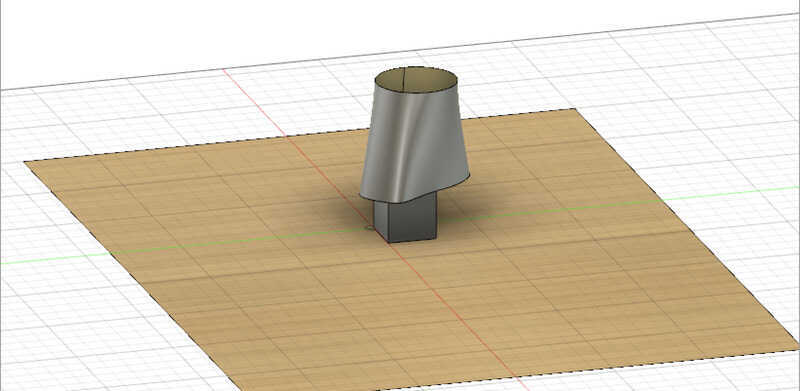
After the lessons I figured that the loft-tool did not work with me, things were intersecting, and the loft tool seems very cool to join different shapes in combination with 3D-printing. So after all the workshops I tried myself to
make a loft. I have to remember that this is only a surface at the moment, so If i want to do anything with it I would need to thicken it.
introduction to other tools.
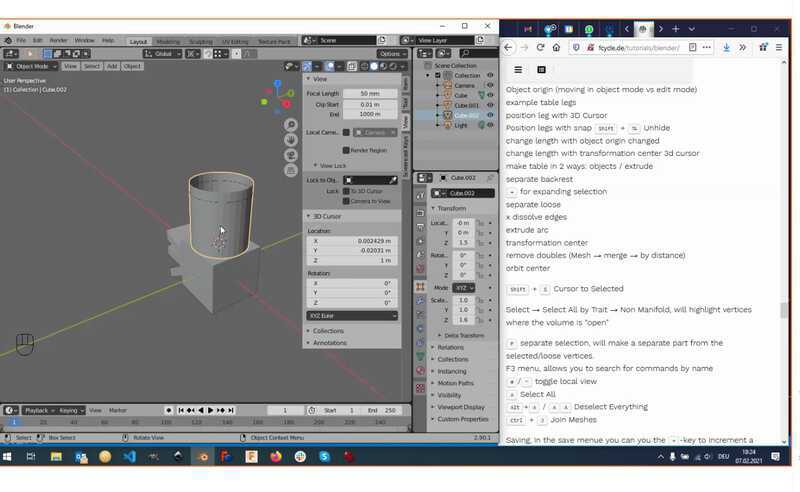
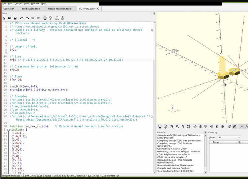
Henk and Luc explained parametric design and the use of it in the FabAcademy. They also showed opensCAD, which is a very different way of approaching a 3D-model, because the whole set is build up in formulas. It has an extremely steep learning curve but for simple models that could have different parameters it can be quite useful.
| bolt M8 | solarpanelholder |
|---|---|
 |
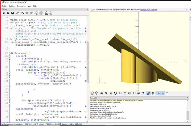 |
The steep learning curve caught me and I gave up for this week. I might try and find some examples that I can use in my own projects the coming weeks.
FreeCAD
With the great enthusiasm of Neil (only the name is a disadvatage) and with the upcoming assignments where parametric design is important, I thought it would be a good idea to try out FreeCAD. I first tried to just open a freecad file and look around, but the system that freecad uses to build the objects is so different form that of Blender or Fusion that i did not get far. So back to finding tutorials.
First i tried a very basic tutorial from Jayanam on youtube.
 It was quite difficult to follow because ot looks like the outlining of my windows/icons/toolbars on my mac BigSur is very different from the one that he is smoothly using in the video. But after quite a long search around the top of my program I noticed that half of the options was hidden far to the right.
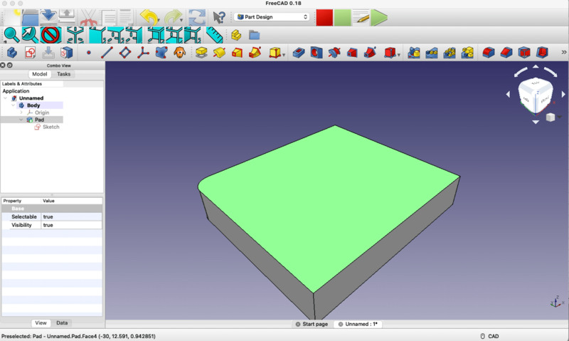 It all looked very different, so I did a lot of things not right, my box would have too many constraints or it was impossible to mirror a side around the axis. I had to start over several times and look very carefully which options were taken to solve this beginner-tutorial.
Second step
Anyway, I did like the way the program works and I think with a good set of tutorials I can get the hang of this.
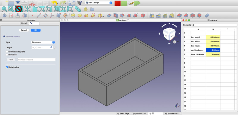
So I started my second experiment and found a great tutorial about designing a box completely parametric
Again with a completely different look and feel, so it was especially hard on getting the right when I had to follow the steps by doing something in one of the top-bars. It was quite complicated to set the parameters,
- First step is to open the spreadsheet-workbench,
- make a new spreadsheet on the left upperside
- open the spreadsheet. in the left menu
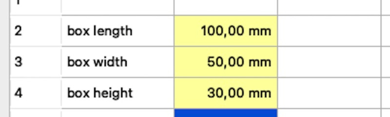
- In column A you can set the names of the measurements
- in column B the amounts.
- then select every parameter separately and give it an 'Alias' (In my view only possible by rightclick, in the video there was a standard box to type) without space in the name (this is the name that will be used in the formulae).
- then set the properties for all of them to millimeters 'mm'
- go to the model-tab and rename 'spreadsheet' into something that is short and understandable. (This is the name that will be used in the formulae)
Then in the sketch build the lines and with setting the length instead of putting a number, choose to put a formula and put spreadsheetname.aliasname to enter the right amount. it is also possible to make formulae with adding, subtrackting and so on.
 With a lot of patience I did get it to work and I managed to make a nice parametric box. I played around with the parametrics in my spreadsheet on the side.
Freecad has a very nice wiki, with all the formulae you can use and a lot of hands on infromation:
Vector-drawing in Illustrator: first step.
Last week I tried to make my drawing into a vector-based SVG so I could put it on my site. For this I looked for an online tutorial on making an icon out of a drawing.
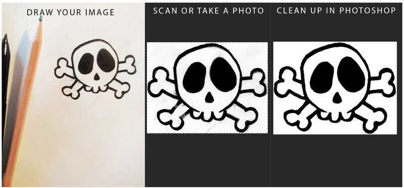
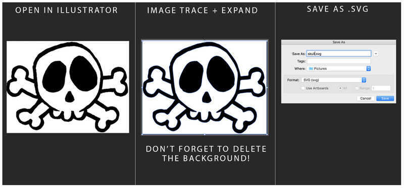
The nice thing of this tutorial was that it just explained the steps visually, instead of using Video. I like that a lot, because I can work in my own time and in the end it is much faster, because I don't have to switch between the tutorial window and the illustrator window.
Illustrator tutorials.
On sunday I was working out how Illustrator really is working. I started out with some basic tutorials that Illustrator offers on starting the program.

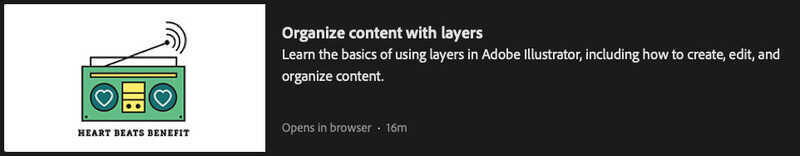

But I soon found out that these tutorials are for absolute beginners, and I know my way around Photoshop and understand layers and drawing. But at least I heard all the basics again and so I changed strategy and would do tutorials about the things I needed in my own work.
First Experiments
Illustrator
My goal was to make a screen for my final project. As a starting point I would take the drawing that I made last week.
first attempt
So my first try was to make a worm build up out of several circles and connecting them
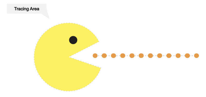
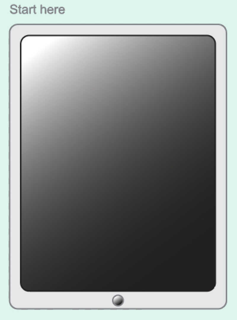
 For this I needed several tutorials especially the Pacman-tutorial helped me to make dotted lines and to cut circles in parts and how to make a simple 'screen'
| paths & circles | gradient & align |
|---|---|
 |
 |
Second try
I needed more, and looked online for tutorials and found a great one about making a worm which would explain the use of blend,
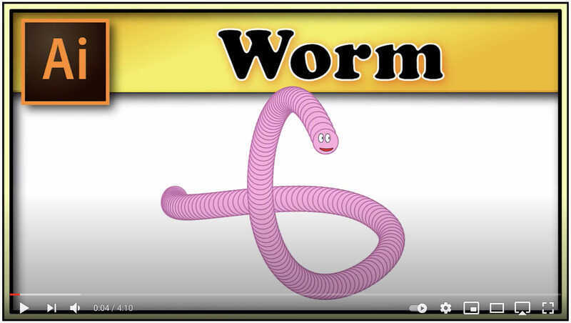 After following this tutorial I made my own second set of worms. It took quite a long time to change all the colours, because in this way I had to pick the first circle of the path and the end-circle and since I wanted a gradient I had to change colors of the fill and the line a lot of times, because if not picked carefully the colors would clash.
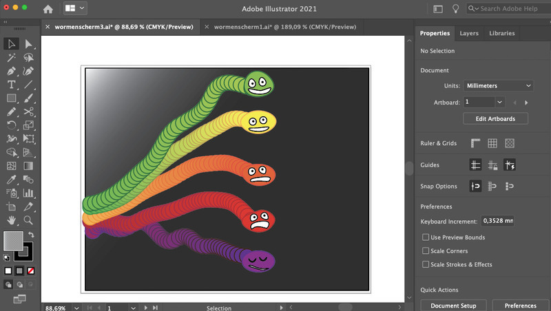 I showed this to my family and they said it was no-way close to what my first drawing was like and the 'happy worm looks like a farmer with a toothache, and worms don't have teeth." Hmmmm learned a lot but no success.
third attempt
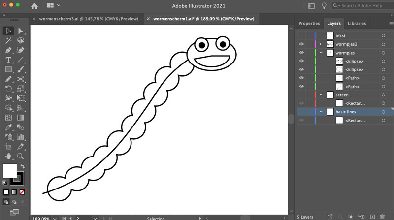
So what to do, my skills in Illustrator are not good enough to start from scratch so I go back to my first learnings in illustrator, I just need a nice and simple drawing of a worm and I can trace that and have the basics for my own worm.
| online google picture | cleaned up image in Photoshop |
|---|---|
 |
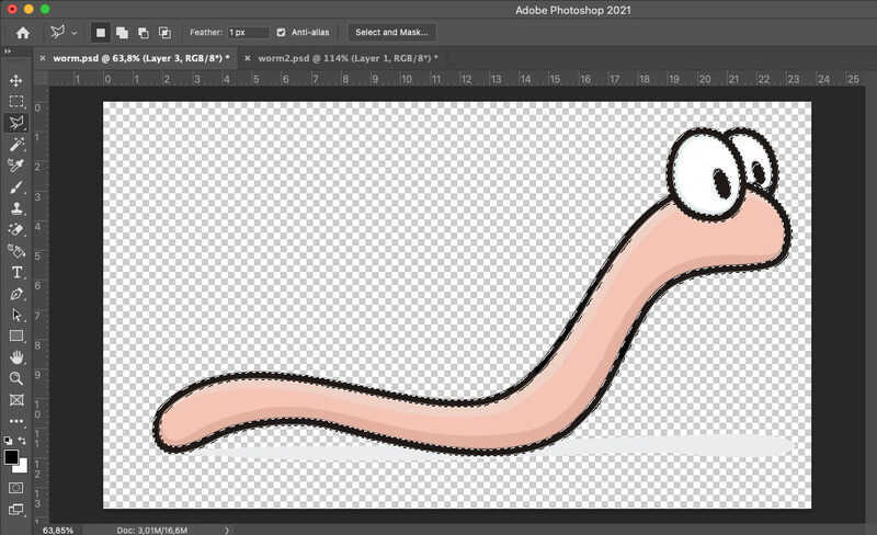 |
After getting stuck several times with the steps of my first tracing I only got the trace of the square around the worm. So I split the whole thing up in layers in photoshop and traced the different layers... that would not work either.
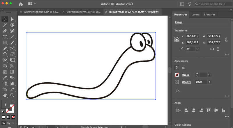 I ended up with a photoshop-file in which I only kept the black lines. this way I could finally trace my new friend the worm. He was build up out of all these lines and white shapes and that would make it quite complicated to alter the shape. So I copied only the white worm-shape and gave it a nice stroke, then copied the 2 white eye-shapes, deleted the holes for the pupils and gave them a stroke. added two new pupils and a mouth. Finally I gave him a nice gradient color to start with
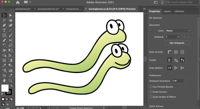
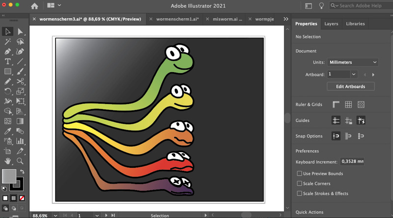
The final worms for this week
So after a lot of learning and 2 days of Illustrator tutorials I made my friendly set of worms for on the screen. I needed to do some more tutorials on anchor-points, the pen-tool and scissors and joining to get the whole thing done, but:
Now my children and their friends are all happy about my drawings and want to see the whole project. And everybody feels very sorry for the bottom worm.
First Experiments 3D-model
After the tutorials in fusion I tried building the housing for my Worm-meter. With looking back at my notes and working steady and slowly and keep going these are the results.
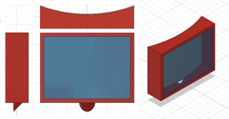
 step 1 make a sketch and extrude with the right parameters
 step 2 turn the housing into a shell and make an opening for the screen, I made the material thickness 2mm
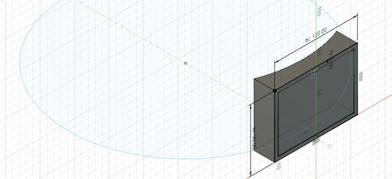
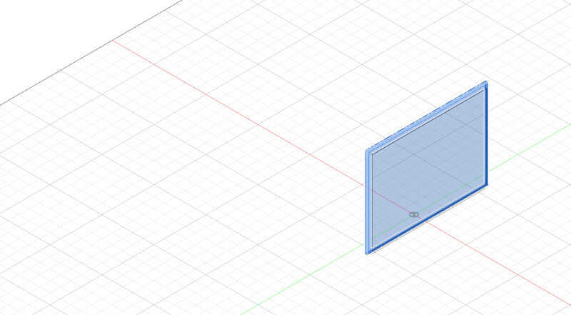 step three building the screen, I made it 4mm thick so I can still take a small rim of the edge so it will fit into the screen-opening
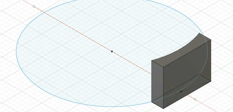
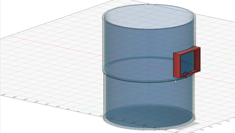
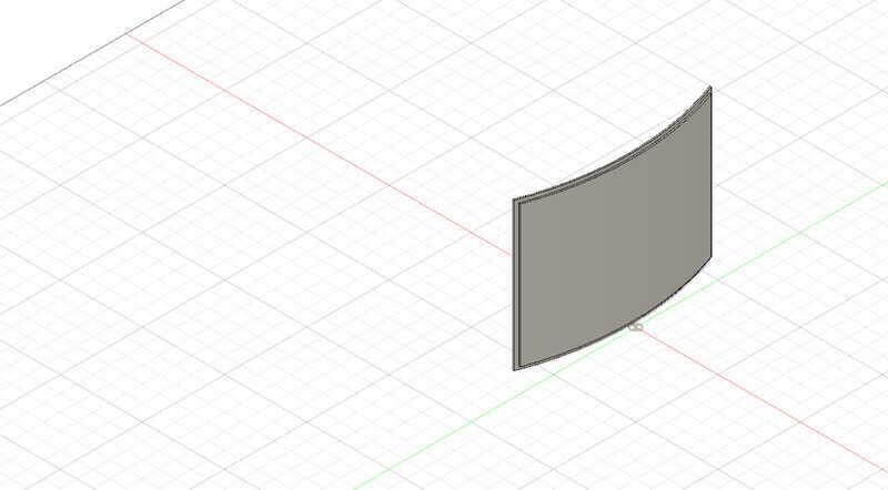 Since the housing has to be on the outside of the existing worm-bin which is curved I measured the real bin and made the back of the housing with the same radius. Here I needed several tries to figure out how to make an extrude that would fit in with the product.
because I had to make a small rim as wel in order to let the back fit in the housing, but on the other hand I did want the parameter 'dieptetotaal' to stay the same, I had to cut off a little bit of the original red housing.
Since the housing has to be on the outside of the existing worm-bin which is curved I measured the real bin and made the back of the housing with the same radius. Here I needed several tries to figure out how to make an extrude that would fit in with the product.
because I had to make a small rim as wel in order to let the back fit in the housing, but on the other hand I did want the parameter 'dieptetotaal' to stay the same, I had to cut off a little bit of the original red housing.
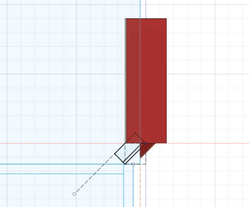
Last step was to make the opening for the sensors, I made this by connecting a hollow pipe to the bottom of the housing at an angle of 45 degrees and cut away all the intersecting parts with the housing and the bin.
 |
My first try I did not think of the curved backing and it ended up to be placed in the air, so I had to build the bin as wel, because I had to find out how big the opening had to be. |
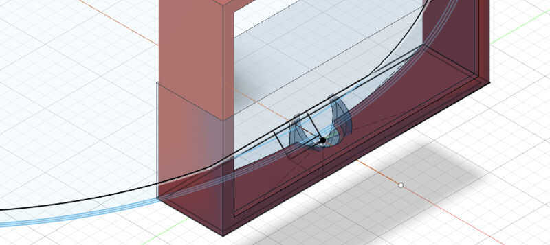 |
Building the bin as wel as the housing came in handy, because I needed to cut away parts of the sensor-opening and with a curved surface it was the easiest way to build the entire bin. and this way it is nicer to see the total as wel. |
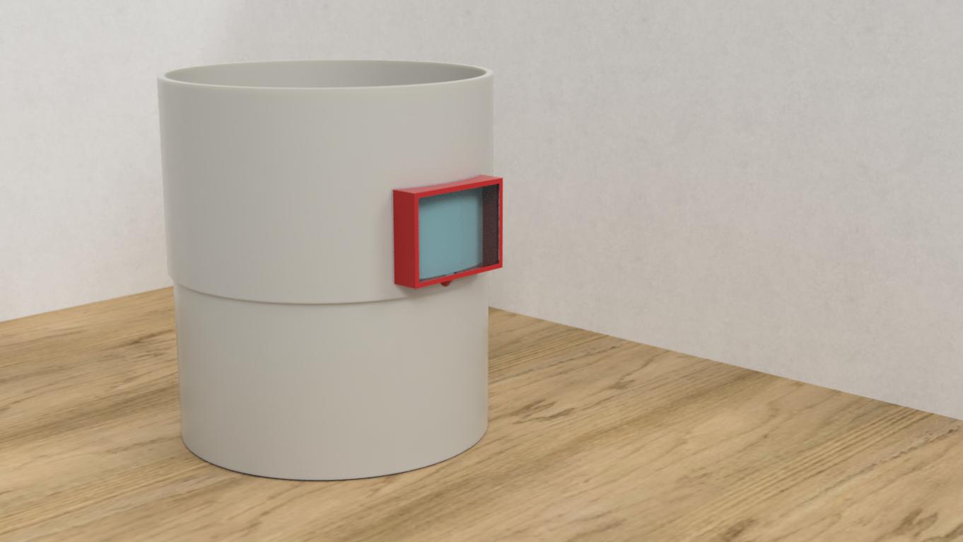
So for now the housing is complete, Of course there is a lot to think about, technically and for example how to attach it to the right bin, but the result of building it with fusion is finished.
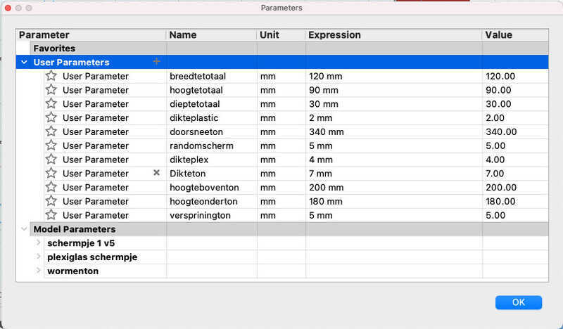
Setting the parameters was really something I had to learn. By deciding about certain parts I had to make decisions about other parts as wel. But since I only had that one drawing I made last week there were not many measurements that were fixed. So for now I just looked at an arduino and a square battery to think roughly about the measurements.
so I ended up
I worked to get a render in fusion
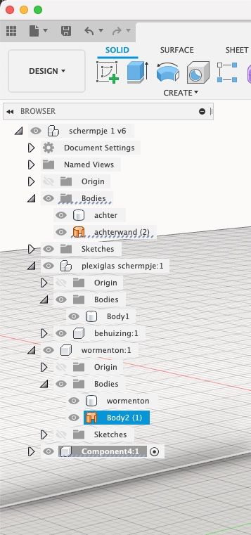 |
I tried to make a exploded view of all the parts, but here I really got stuck, because I messed up everything with the components and bodies and I could not figure out a way to fix that. |
Illustrator second part.
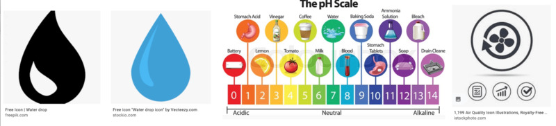
I was all happy with my worms, it is too simple though to tell what is wrong with them by just seeing them unhappy on the outside. so I would need some icons to tell what is wrong with them. since I don't know yet what will be the right electronics to measure with I thought it would be important to say something about the amount of fluid in the compost, something about the pH-value in the compost and something about the amount of fresh air. 9might be CO2 or Oxigen or maybe some more chemical measurement that I need.
To learn a bit more about Illustrator I thought I could make nice icons for these three measurements on the screen.
I looked on the web for inspiration, I did not copy them but started building my own set of icons from scratch.
And worked with different skills in illustrator, drawing shapes, spacing and aligning objects adding/deleting and modifying anchorpoints and join/group and work with color-swatches. I really learned from my first experiment with the worms and this time I was much faster and did not have to use tutorials. Although I do not know what the exact output of my wormmeter will be for now I have a good idea what it is all about. Here is the finished .SVG file

Other programs I used and tried making the images.
- Preview (to preview, crop and small alterings)
- Photoshop (to clean up, improve images and combine the different views of my wormmeter)
- Imagemagick (to convert .png to jpg's (screenshots) and give them a standard width (800 or if wanted smaller))
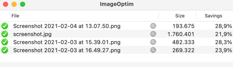
- Imageoptim, a nice little program to compress images by just drag and drop.
Douwe told me that it is possible to change the format that my mac is saving the images when I do a printscreen. Which is great, because I am spending quite some time in Imagemagick changing it in the batches that I want to publish in my documentation. I found it online, in Terminal it is possible to change the default:
defaults write com.apple.screencapture type jpg;killall SystemUIServer It works great.
to edit the video I used photo's on my phone to crop it, and send it to myself in Whatsapp (that way you vcan easily select the clip and it rezises the video automatically) and then used Handbrake to make the video smaller and remove the audio.
To insert video I should use this, but I haven't figured out it right yet:
1<figure class="video_container">
2  <video controls="true" width="100%" allowfullscreen="true" poster="../week2/name.jpg">
3    <source src="../week2/name.mp4" type="video/mp4">
4  </video>
5</figure>
I have the figure, but can't get the video working yet. Her I try it with 6 different ways: different ways to make the link and different ways to set the video. (Later I found that my old HUGO-theme was blocking all the Raw HTML) So because therefore I switched to a new personalized theme some of the try-outs do work. Under the 6 tries I will explain my conclusion.
1 Here the link to the video is not right.
2 Here everything looks fine, this clearly is the winner.
2B number 2 with shorter link
3 Weird is that only the link is different than in nr 2, bso it can only find the 'poster' and not the linked video.
4 Same as 3
5 Is not working at all
6 This one is interesting, because it is a different way of calling for the video. Later I made working with the right link, but seems promising since it does show up in my new theme.
the working result:
Number 2 and nr 6 are the winners, these are the codes that is working fine now. For nr 2:
1<figure class="video_container">
2  <video controls="true" allowfullscreen="true" poster="wormenvideo.jpg">
3    <source src="../week2/video/wormen2.mp4" type="video/mp4">
4  </video>
5</figure>
for nr 6:
1<video controls src="./video/wormen2.mp4"></video>
Learnings this week
This week was fun to do I learned a lot about the different tools and played around with the idea of my worm-bin-measurements:
- It was quite a thing to finally work with illustrator since it works different than Photoshop I always was confused, but I am happy that I can use it now. I finally got past the real basics. It is a very cool program with a million options, I will use this more and more form now on. (not only during Fab-academy, but also in my daily job at the Hogeschool van Amsterdam)
- Fusion is a fun program to work with, it is nice to work towards a product that is already in your head, that way I had to figure out what a nice way towards the goal is. It is like working as a digital carpenter.
- I am happy I tried freecad and I found that this is not the program for me. The focus is to much on the mathematical side and I feel lost.
- I am more a carpenter than a mathematician. Fusion fits me more than FreeCad.
- Blender is a real cool 3D-prgramm and I am really happy that I followed the lessons on sunday-evening, (Ferdi is the best...!) I will try and use this if I am working in 3D.
- uploading a video is not as easy as I thought. My previous Hugo-theme would not easioly let me do that. So it did not work at first. (but this gives me good insight in what to look for with the Hugo-theme I'll choose, in the coming weeks I will change the theme and also in this week things are functioning then.)
- this week I worked with preparing the images for online, but I did not find the best way yet. I will work on that as well the coming weeks.
links to CAD-files
here are the links to the designfiles of this week: