Week 10
Mechanical Design part2
Group assignment Actuate and automate your machine. Document the groupswork.
Individual assignment Document your individual contribution.
Group assignment
 - Actuate and automate your machine. Document the groupswork.
 - find the places where i can be of help besides the lights and finish the lights. Understand the power better.
 - figure out the power questions
 - learn learn learn
We got very far with the group assignment last week, also due to the fact that its easter weekend so many of us were enjoying a weekend of searching for eggs instead of parameters. Nadieh spend the week at the Waag lasercutting the pedals and other parts of our mechanical flower. Lucky enough i was able to spend also a day at the Waag whcih gave us the opportunity to work a bit together, putting the flower together with bolts, rings and nuts. If you wanna read more of this process i would direct you to Nadieh her Fabsite
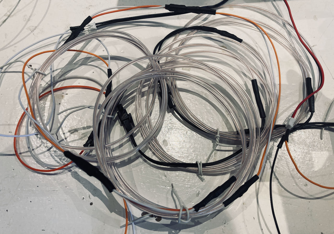
I first thought i could be a bit more useful by trying to figure out the power needed for the structure while also finishing the Elwire. In the process of making the ELwrie i learned a lot and also realized i really don’t understand power. I can calculate it but have no understanding off the natural process.
Knowing this made me a bit more careful which is not a bad thing when dealing with power.
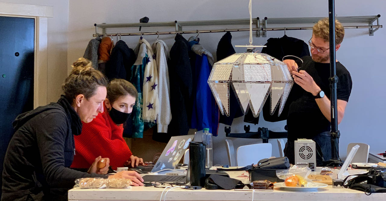
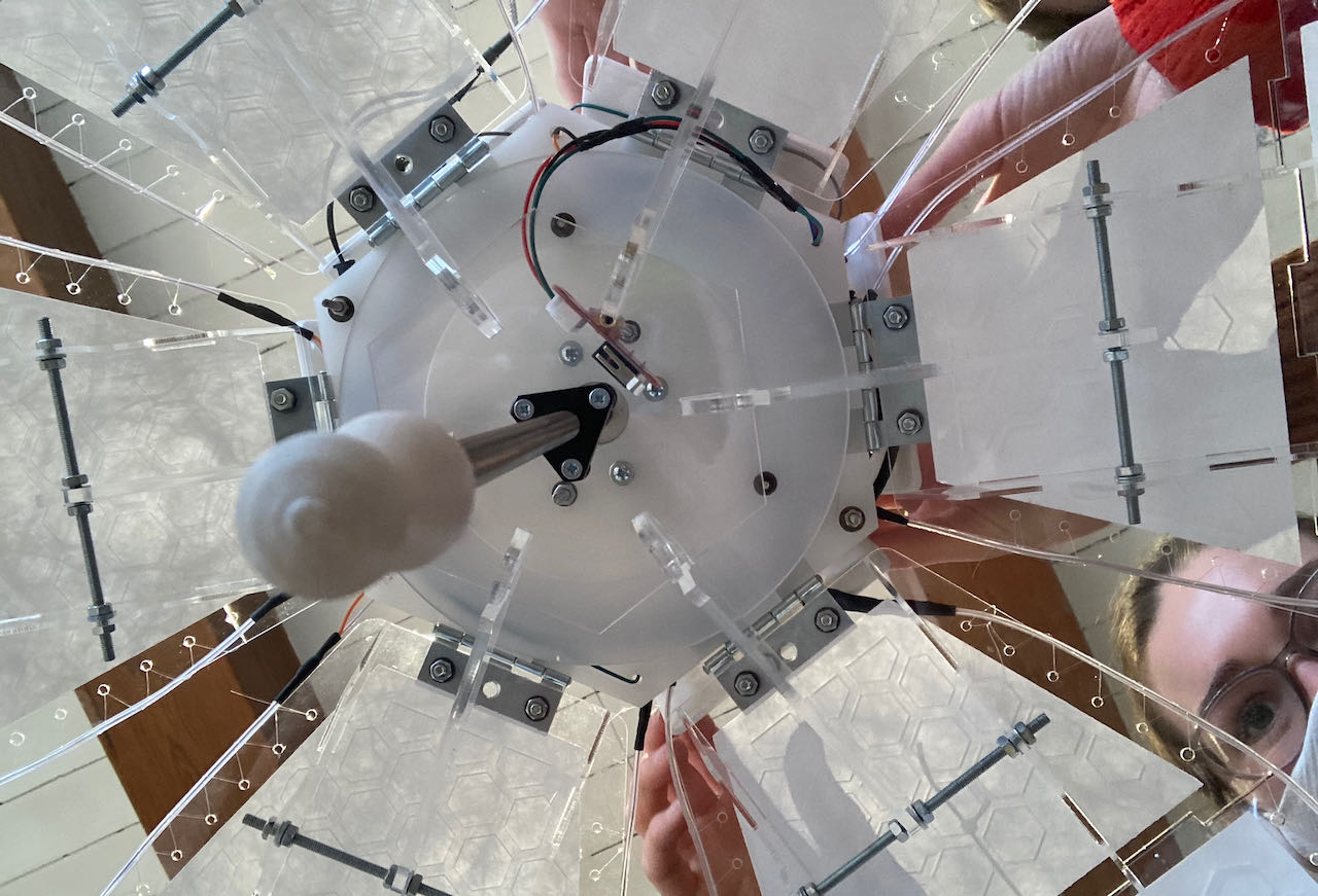
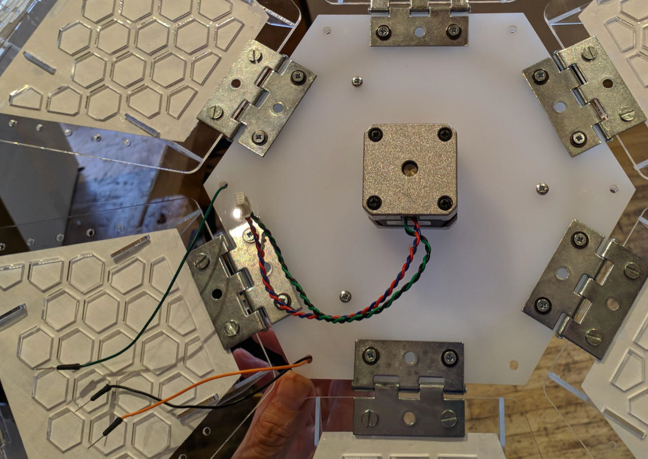
The last days of this week were a bit hectic, not only was it finally time for me to put the theory into action now that most of the parts have arrived but also it was time to put all the pieces of the puzzle together. One of our groupmembers lives on the other side of the Netherlands and unfortunately got a big migraine attack on the day when we should start putting it all together. She had the very important task to figure out the stepmotor plus the hanging system and designed most of the mechanical parts of the flower.. so you can imagine we had a gap to fill. So first things first, to be able to test the motor flo has to hang so in a combined effort we made another top plate with some extra holes for bolts and cables, Douwe attached a lifting eye bolt to it and the party could begin.
Luckily enough i was able to finish the Elwire the day before just had to still install them on the pedals, and this is when Douwe stood up and took the job off finishing that. Thanks for that Douwe, i know it was not the most fun job to do, putting fishline through tiny hole to fix the Elwire on the edge of the pedals.
Putting flo together
Nadieh is the one that volunteered to put it all together on the programming side and i was her sidekick while trying to figure out the power supply. Both of the tasks needed some input from Henk since we were lacking some knowledge. It was so much fun trying to figure it out, there were a few spirals at the same time and tasks overlapping but since we were able to work organically and smoothly together it felt like a blast (with some fun stress moments).
Arduino in combination with an ESP32
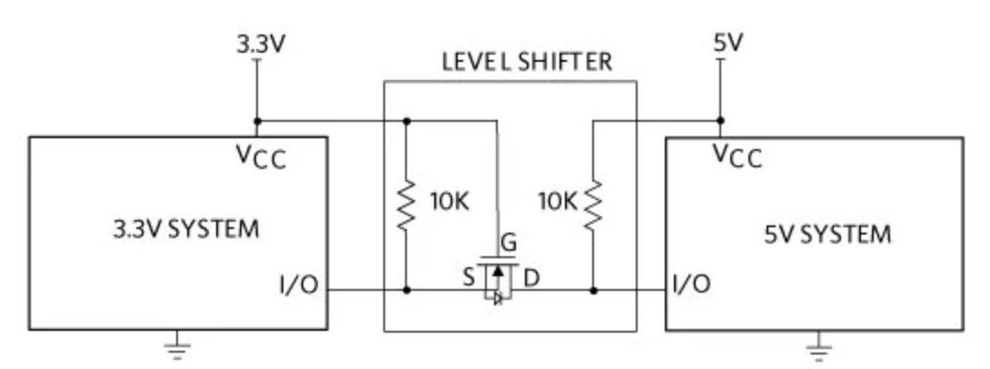
During this process i was really just the side kick trying to help out soldering different cable connections, resistors in between connections. At one point we got stuck when the only way it seemed to be able to work is when we could lower the signal on the RX from the Arduino to 3.3V so it was able to communicate with the TX from the ESP32. We didn’t really know where to start searching so when we realized that the originalLogic Level Converter was not available at the Waag.
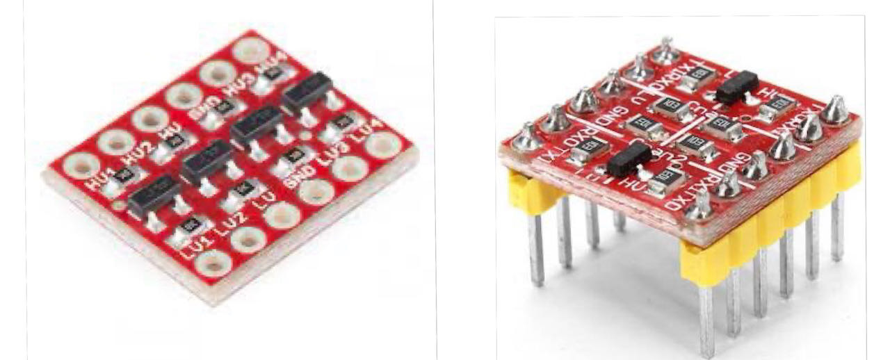
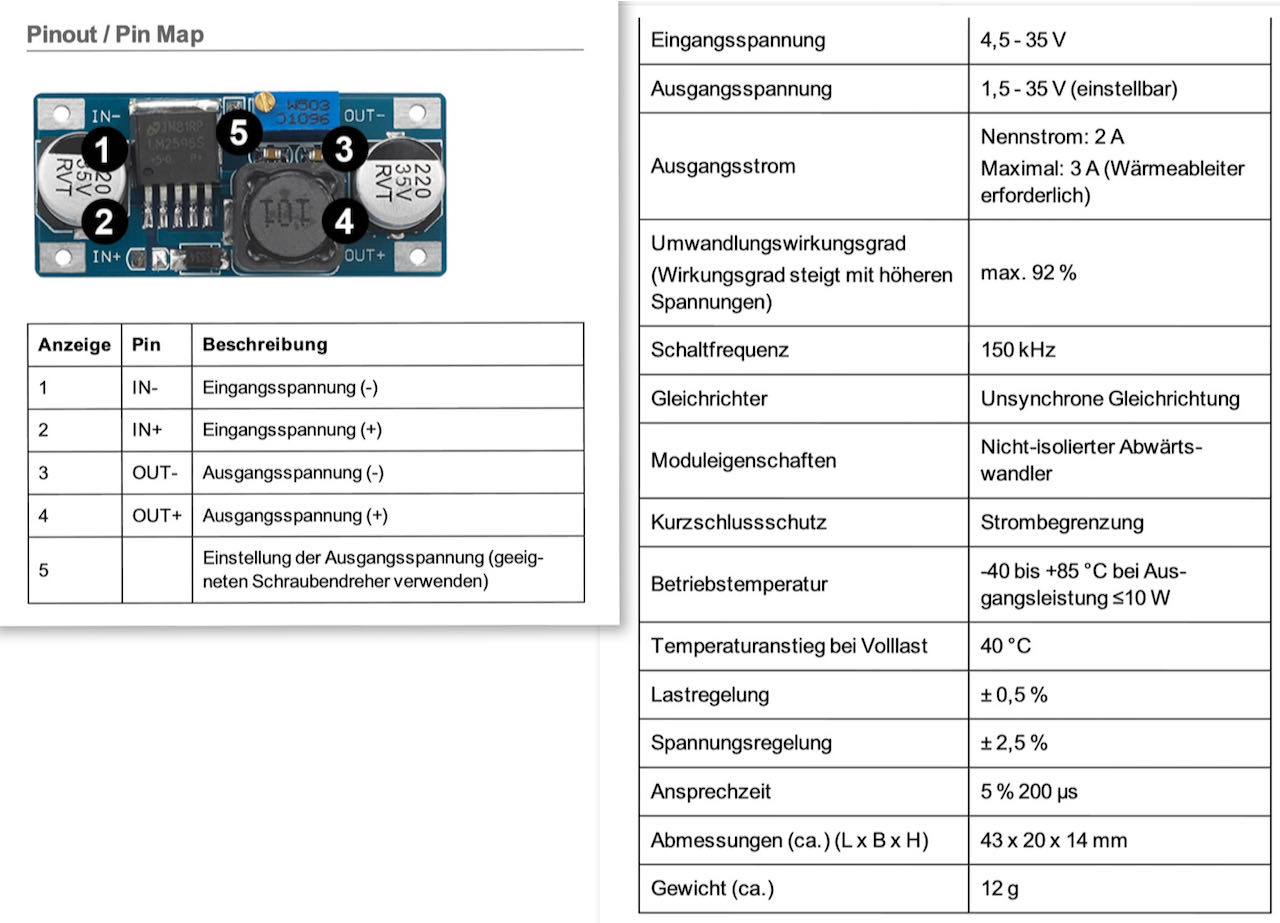
So we called 3 shops and finally the last one had something that seemed similar.. an adjustable stepdown converter. But in retrospective i think its to advanced for what we thought we needed.
It’s in the Waag now so let’s see later during this weeks what we can use it for.
Later on i found out that there were different ways on how to solve this (one way to solve it i found on this website) and Nadieh realized we didn’t need it in the end since we were not sending signal from the Arduino to the ESP32 but both this realizations came when the time pressure was off and we had time to think :)
LDR
That day we had to move on so decided to get the ESP32 out of the way to at least make it work, this would mean that the WIFIsniffer which Douwe reasearched was not working amymore but Nadieh did manage to still put a “simple” LDR on there. The Neopixels and ELwire only needed 5Vsignal and power (the ELwire inverter has separate power which i explain later)
 This also needed a resistor between the one pin and the ground so back to the solder table, Erwin and myself switched places the whole day :). Forgot to take pictures of what i did so made a drawing instead.
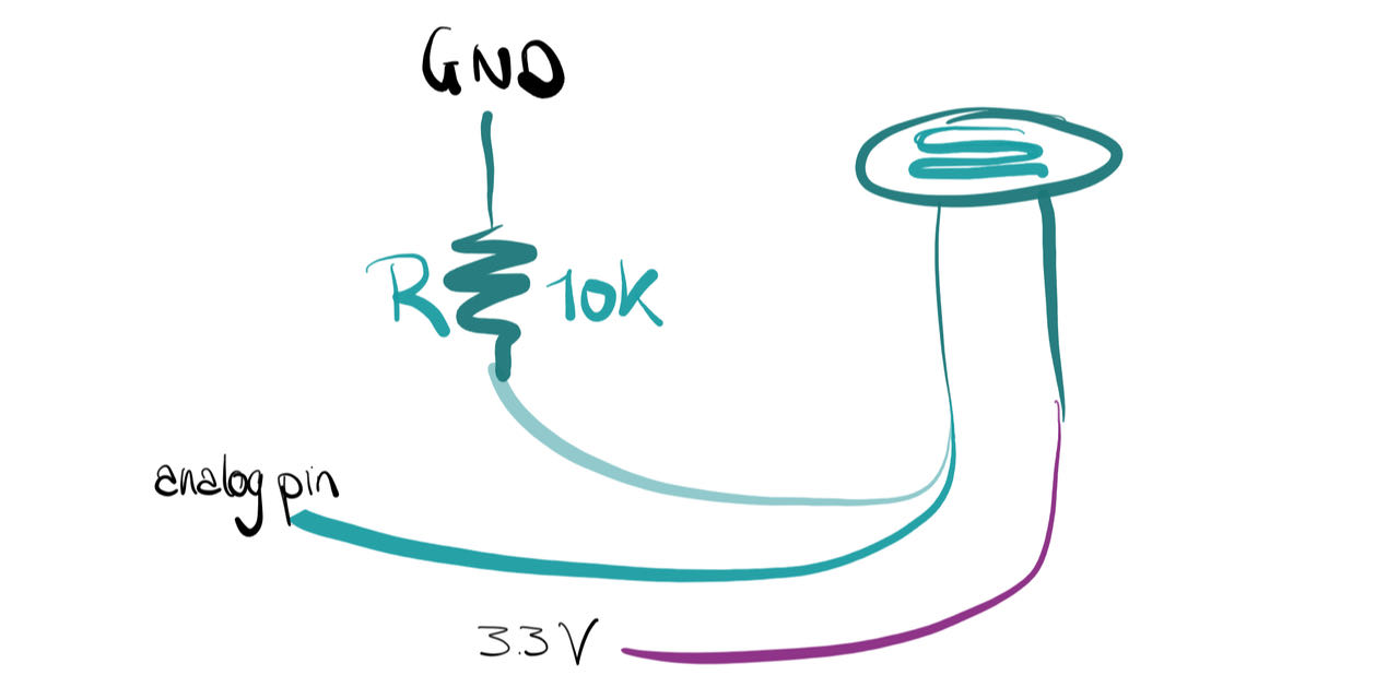
The Arduino converts the analog voltage from 0-5V into a digital signal from 0-1023.
const int ledPin = 13;
const int ldrPin = A0;

void setup() {

Serial.begin(9600);
pinMode(ledPin, OUTPUT);
pinMode(ldrPin, INPUT);
}//void setup

void loop() {

int ldrStatus = analogRead(ldrPin);
if (ldrStatus <= 200) {
digitalWrite(ledPin, HIGH);
Serial.print("Its DARK, Turn on the LED : ");
Serial.println(ldrStatus);

} else {
digitalWrite(ledPin, LOW);
Serial.print("Its BRIGHT, Turn off the LED : ");
Serial.println(ldrStatus);
  }
}//void loop
When Nadieh started to program the stepmoter we quickly realized we need an endstop, Henk was so nice to give us one that he bought for a different machine, so we could continue.
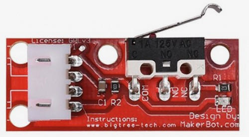
I borrowed the hot glue gun from the other group and attached a long nut the length of the PCB to the endmill so that we can screw the endstop to one of the long bolts that holds the upperplates together. It seems that when using an endstop the when it reaches the switch you should tell the motor to go back a few mm to avoid the switch staying on the whole time.
from Nadieh’s final code:
////////////////////// MOTOR //////////////////////
#define EN        8      //Negative Enable pin
#define X_DIR     5      //Direction pin , of 5 of 6
#define X_STP     2      //Step pin
#define pin_END   12     //End stop of motor

//How many steps away from the "total open" state is the total closed state
const long closed_position = 62000;
//The total open state (which I'll set to be 0 steps)
const long open_position = 0;
//Important variable that will keep track of how many steps the hex plateau is actually away from the "total open" state
long total_steps = 0;
//End stop sensor value, 1 = open, 0 = closed
int value_END = 1;
//These two will keep track if the lamp is fully opened or full closed at any point
int flower_full_open = false;
int flower_full_close = false;

//Motor
const int delayTime = 50; //Delay between each pause (uS) //versnellen en langzamer laten lopen
const int stps = 6400;// Steps to move microsteps 1/32 (200*32 = 6400)

//Will be set to true at the start of the program, to make the lamp move up until it reaches the end stop
//and thereby I can set the total_steps to 0 at that point
bool first_activate;

//---------------------------------------------------------------------------------
void step(boolean dir, byte dirPin, byte stepperPin, int steps) {
  digitalWrite(dirPin, dir); //

  for (int i = 0; i < steps; i++) {
    digitalWrite(stepperPin, HIGH);
    delayMicroseconds(delayTime);
    digitalWrite(stepperPin, LOW);
    delayMicroseconds(delayTime);
  }//for i
}//void step

//Close the lamp by 800 microsteps
void closeLamp() {
  step(true, X_DIR, X_STP, 800);
  //Keep track of how many steps we are along the metal rod
  total_steps = total_steps + 800;
}//void closeLamp

//Open the lamp by 800 microsteps
void openLamp() {
  step(false, X_DIR, X_STP, 800);
  //Keep track of how many steps we are along the metal rod
  total_steps = total_steps - 800;
  //delay(0);
}//void openLamp

//---------------------------------------------------------------------------------
    //Move the lamp down a bit so it doesn't interfere with the end stop anymore
    for(int i = 0; i < 10; i++) {
      closeLamp();
    }//for i
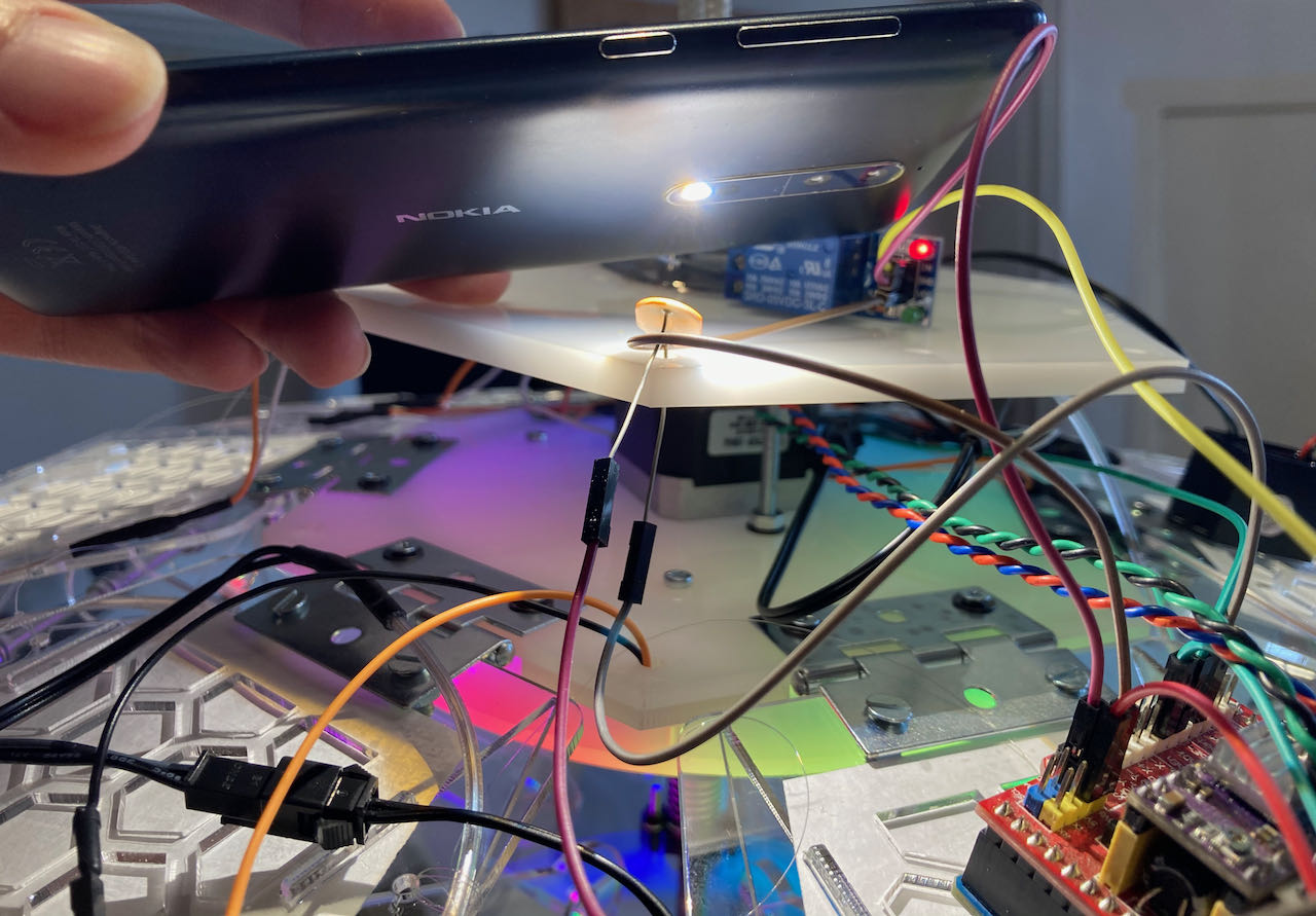
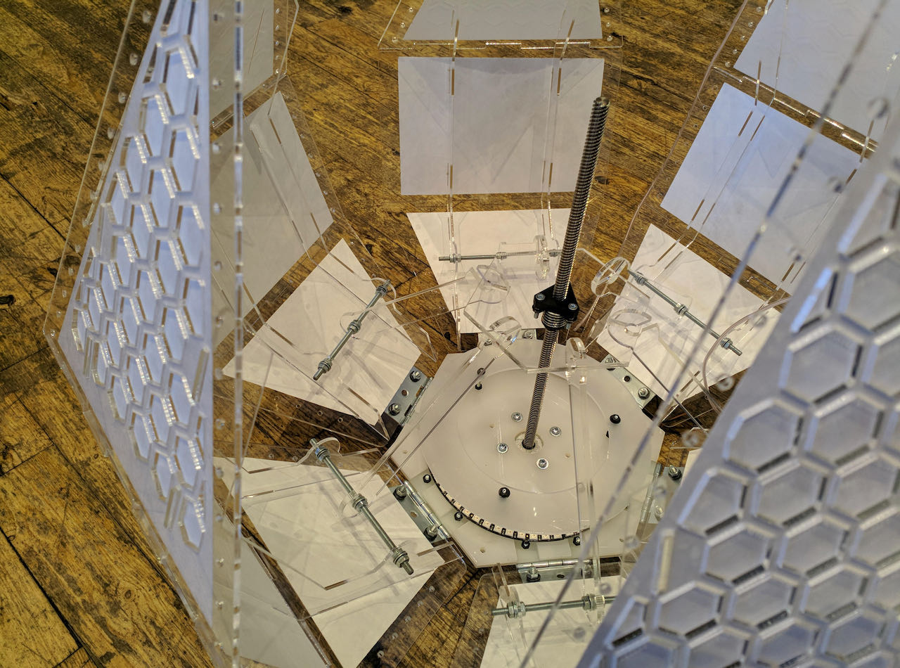
I learned so much being able to look over Nadieh’s shoulder while she was figuring out things. On the next picture you can see the endstop attached and the little stop that Nicole made for the bottom of the stepmotor.
wiring & power
The last day we still had to find a way to cover the wires on the top, when we texted Nicole she reacted with full enthusiasm and started to design a way to cover up our spaghetti. She was arriving a bit later at the Waag which gave me a bit of time to think about the power issue.
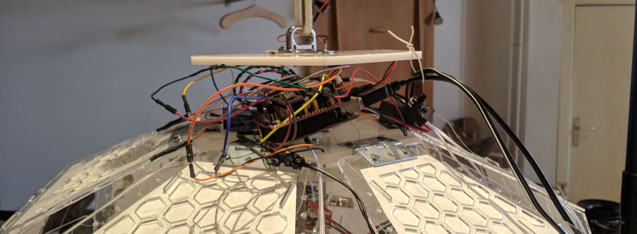
In the end it wasn’t as complicated anymore then when we started.. back then this was the list that Henk came up with ofcourse based on the information we gave him and the components changed during the process.
- 220v for the bulb (original idea which i kicked out by the end of week 9)
- 12v for the stepmotor
- 5v for the de arduino’s
- and optional 3.3v for the esp32
Which ended up being:
- 12V for Arduino which powered the stepmotor
- 4V - 300MA for the ELwire inverter from a adjustable power supply
- an extra 5V/8A for the Arduino
The extra 5V for the Arduino we found out really late and i still don’t understand fully why we needed it but it seemed that when we disconnected the USB from the laptop the arduino didn’t have enough power to drive both the LEDs and the stepmotor. We first tried with a 5V/1.5A but the neolights would go nuts, not sure why, could the 1.5A be to loq?
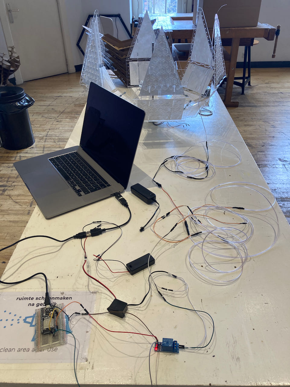
Finally we could close the top part and start filming.
filming
Creating the video was mostly Douwe’s his job with ofcourse some added material since we all have phones with camera’s that are better and better these days.
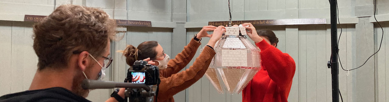
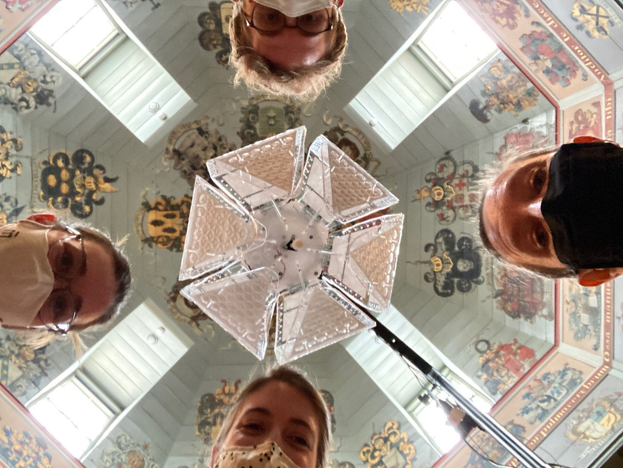
A group picture with tired eyes
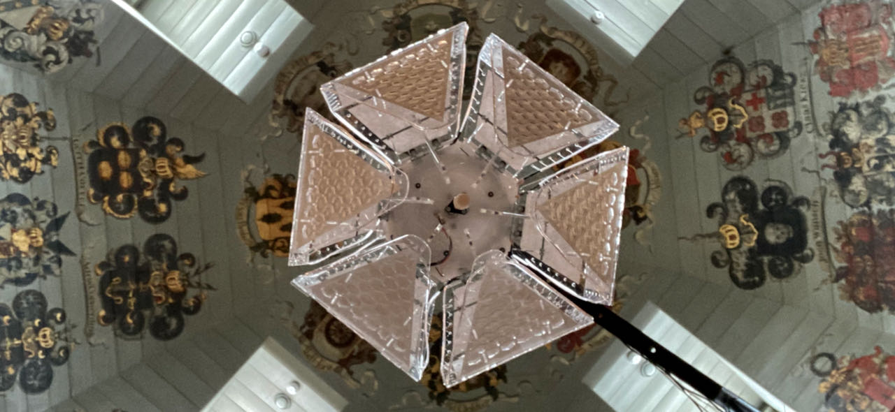
a picture of the light when off
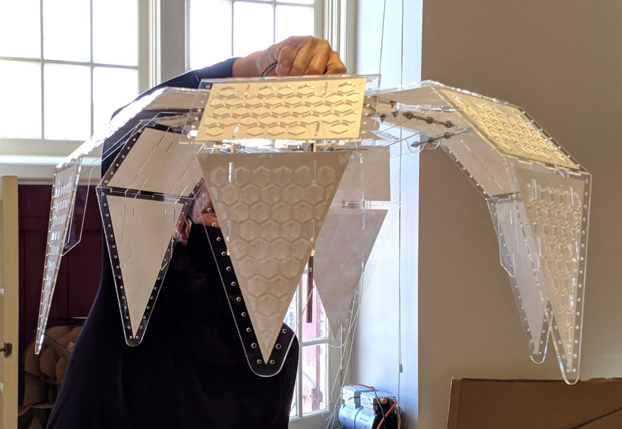
the hero shot :)
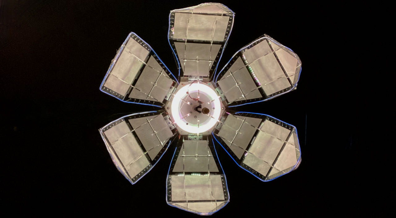
and a hero video, just because i fell in love with flo
individual assignment
- Finish the Neopixel programming and make the Elwire work
- more lights and soldering :)
- figure out how to make the ELwire work (ongoing process)
- make flow breath
Neopixels continued
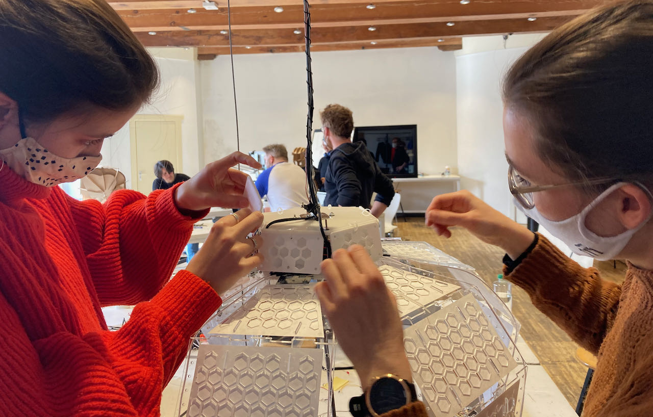
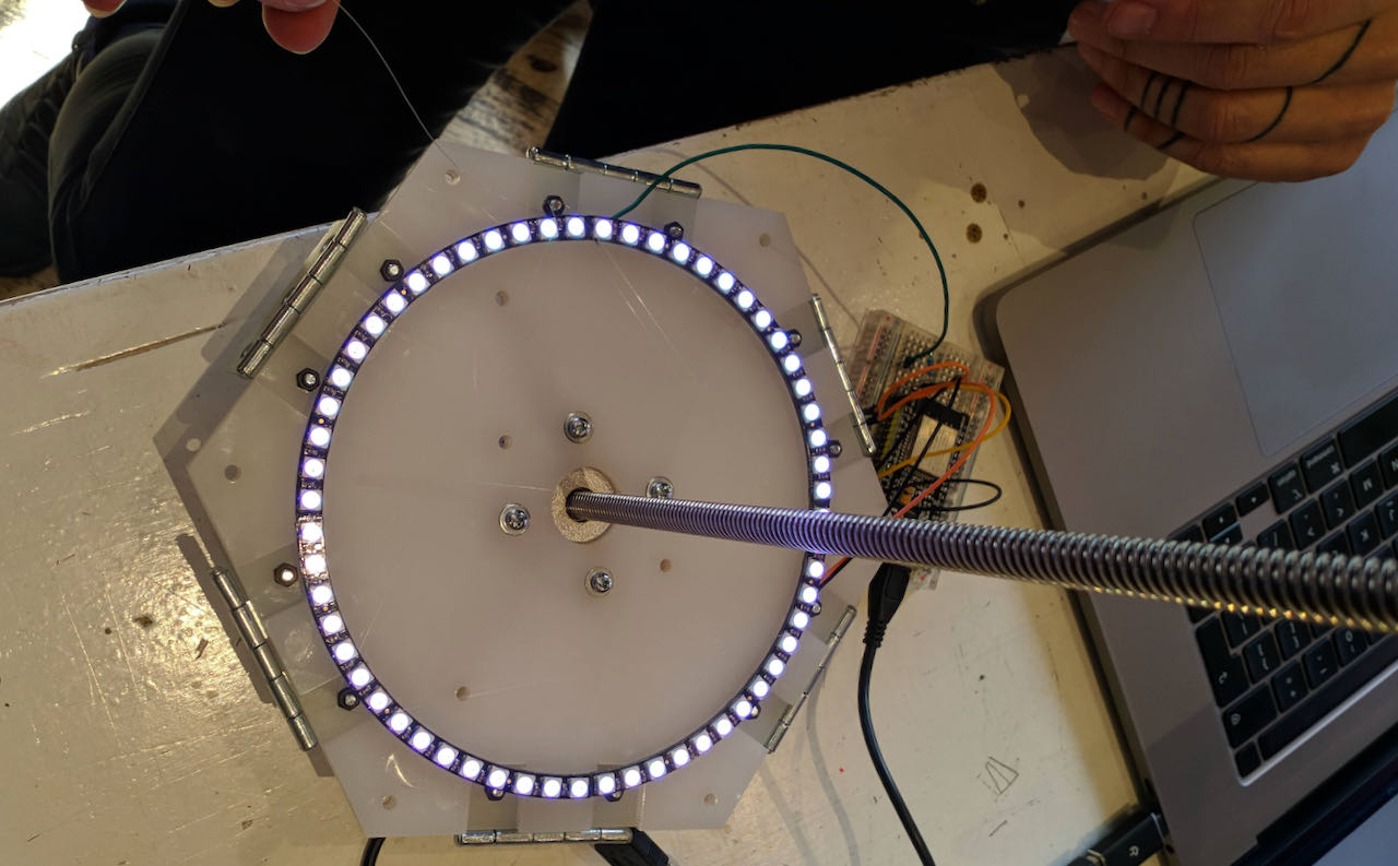
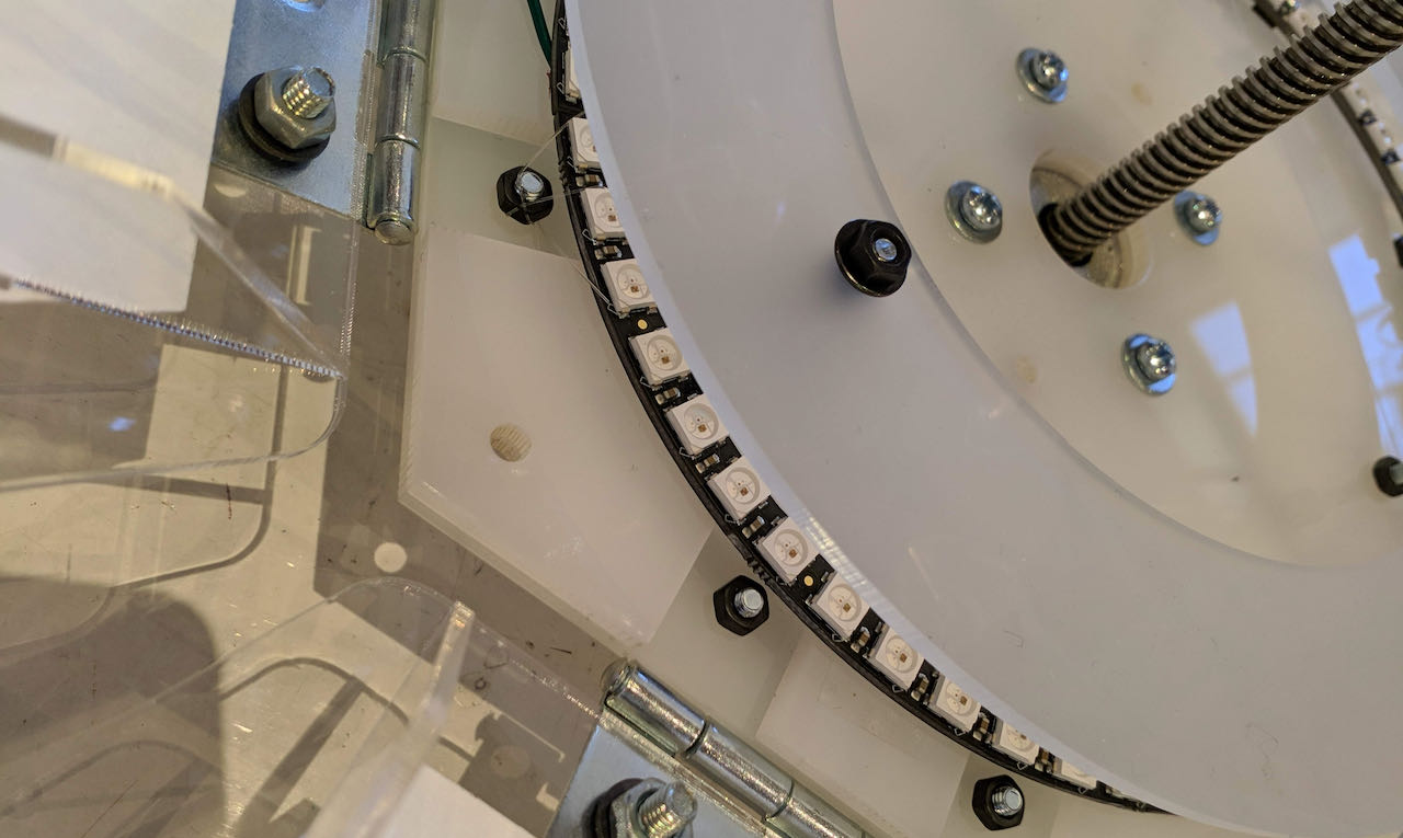
This week started with installing the Neopixels in the structure at the Waag together with Nadieh since she just finished the acrylic structure and we both realized that once the pedals were on, the ring would not be able to be installed anymore without deconstructing the whole flower again. So time for a welcome break from programming with some hands on work.
We didn’t think long enough on forehand on how to install the ring, thinking a bit of double sided tape would do the trick.. which it does but not firmly enough since the ring is not fully flat because of the cables going out of the bottom.. if we thought about it before we could have made some holes.
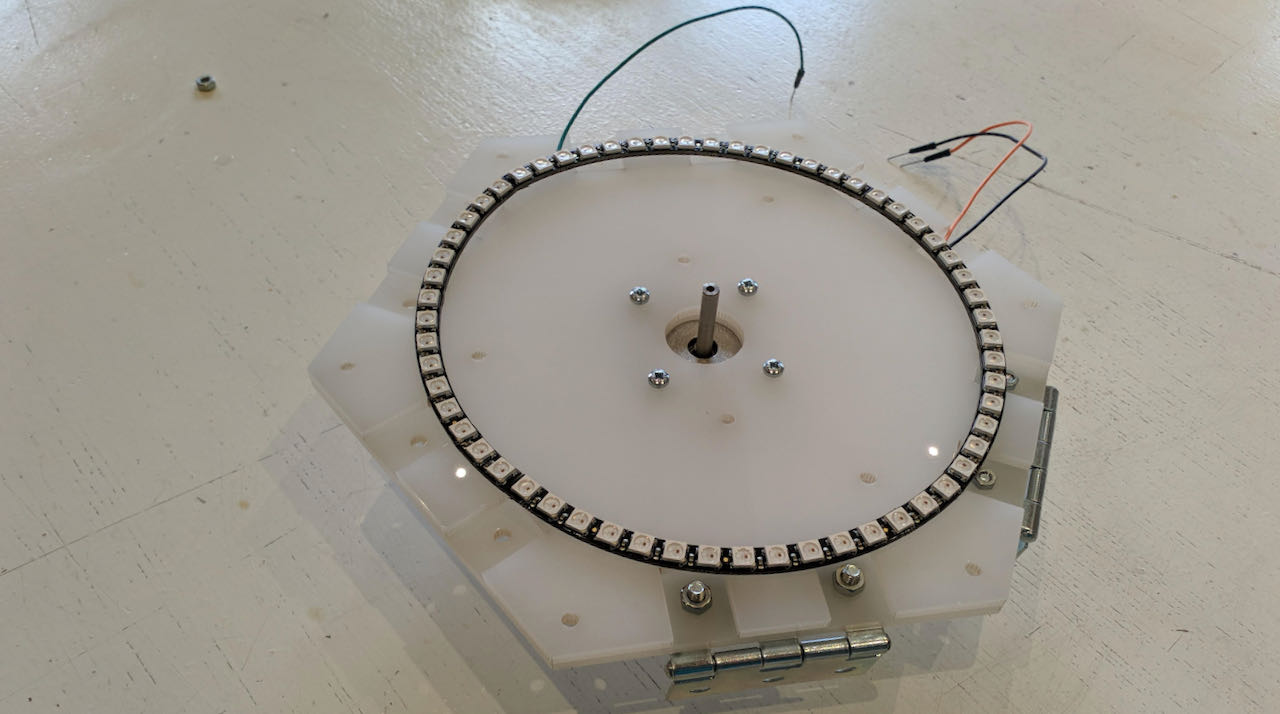
But it did give us the option to be a bit more creative, which is more fun anyways. After some thoughts we decided to use the fishline that we had for the Elwire on the Neopixels also. By making a triangle between some of the bolts it was so snug tight that we could actually toggle the strings.
Connected it to to ESP and temporarily breadboard since we need a 330 Ohm resistor to lower the Voltage of the signal a bit.
Acrylic milky cover ring
Knowing that i need a ring to cover the leds so that it’s frosted is one thing, fitting it into the design is another. With this kind of design when everything is depending on each other it complicated to find your “place” in the order of things. As a light designer i am used to being the last one in line which ended up being the same now, so at the Waag we figured out the measurements of the ring and with 3 bolts keeping the distance from the ring. Nadieh was so nice to draw and laser cut it and the actual distance we could alternate within the limits of the structure.
Programming
I tried some programming before we installed it Understood the basis setting you need and ofcourse installed the Neopixel library.
#include <Adafruit_NeoPixel.h>
#define PIN 14
#define ledCount 60

Adafruit_NeoPixel strip = Adafruit_NeoPixel(ledCount, PIN, NEO_GRB + NEO_KHZ800); //first number controls the amount of pixels you have (add 4 so the drip falls off the edge)

void setup() {
  Serial.begin(9600); // open the serial port at 9600 bps:
  strip.begin();
  strip.show(); // Initialize all pixels to 'off'
}
While installing completely forgot to think about the zero LED, the LED from which the programming starts counting. We just took half an hour and lots of focus to put the fishline in between the bolts so we decided to “fix” it with programming. Which was more complicated then i thought, but luckily Nadieh had some previous programming experience so was able to help me figure this out.
The original question i had was how to figure out sections in the LED ring which ended up in this code which makes mathematical sense to me now.
 void Hexlights without zero(){
 int num_sections = 6;
 }
 for(int i = 0; i < ledCount; i++) {
 setHSV(i, (floor(i/(ledCount/num_sections))) * 360/num_sections, 255, 255);
 }

 strip.show();


 }//void HexLights without zero
Hexlight without Zero resulted in this from the NEOpixels:
// find Zero
void ZeroLight(){
for(int i = 0; i < ledCount; i++) {
int baseColor = 180;
if(i == 5) baseColor = 0;
 setHSV(i, baseColor, 255, 255);
}

strip.show();

 }//void ZeroLight
Zerolight resulted in this from the NEOpixels:
  void HexLights(){
    int num_sections = 6;
    int zero_led = 6;

    for(int i = 0; i < ledCount; i++) {
      int Hue = (floor(((i-zero_led+ledCount)%ledCount)/(ledCount/num_sections))) * 360/num_sections;
      setHSV(i, Hue, 255, 255);
    }
      //Serial.println((i-zero_led+ledCount)%ledCount);

    strip.show();
    //delay(10);

     }//void HexLights
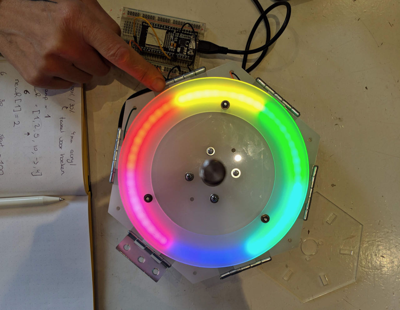
Hexlight resulted in this from the NEOpixels:
We found the new ZERO :) the math behind it is complicated for me but it actually makes sense if you write it out.
There were some holes in the bottom which we were planning to use for the ELwire but they are to small for a reason that doesn’t make sense since it was the right size in Fushion, but maybe we pressed a bit to hard while measuring. Anyways they were very usefull as exits for the connections from the Neopixels.
The whole structure now start to make sense although it stats to get really high tech with the LED and acrylic.
Back at home i still wanted to try to program a bit so i put together a 24 Neoring with a ESP32 to continue, i found a good baseon git which i downloaded and started to play, lots of copy paste but still feel like i got somewhere.
for instance this pastel propellor which is the original code with a bit of alternations.
void pastel_propeller() {
  idex++;
  int thishue = 180;
  int thisdelay = 100;
  int ghue = (thishue + 40) % 255;
  int bhue = (thishue + 70) % 255;
  int N3  = int(ledCount/3);
  int N6  = int(ledCount/6);
  int N12 = int(ledCount/12);
  for(int i = 0; i < N3; i++ ) {
    int j0 = (idex + i + ledCount - N12) % ledCount;
    int j1 = (j0+N3) % ledCount;
    int j2 = (j1+N3) % ledCount;
    //leds[j0] = CHSV(thishue, thissat, 255);
    setHSV(j0,thishue,thissat,255);
    //leds[j1] = CHSV(ghue, thissat, 255);
    setHSV(j1,ghue,thissat,255);
    //leds[j2] = CHSV(bhue, thissat, 255);
    setHSV(j2,bhue,thissat,255);
  }
  strip.show();
  delay(thisdelay);

}//void pastel_propeller
  void blue_flower(){
    int num_sections = 6;
    int zero_led = 6;

    for(int i = 0; i < ledCount; i++) {
      int baseColor = 180;
      int N10  = (ledCount/6);
      int N20  = (ledCount/3);
      int N30 = (ledCount/2);
      int N40 = (ledCount-N20);
      int N50 = (ledCount-N10);
      setHSV(i, baseColor, 255, 255);
       if(i == 0) baseColor = 220;
        if(i == N10) baseColor = 220;
         if(i == N20) baseColor = 220;
          if(i == N30) baseColor = 220;
           if(i == N40) baseColor = 220;
             if(i == N50) baseColor = 220;
             setHSV(i, baseColor, 255, 255);

  if(i == 0 + ledCount/9) baseColor = 0;
        if(i == N10 + ledCount/9) baseColor = 160;
         if(i == N20 + ledCount/9) baseColor = 160;
          if(i == N30 + ledCount/9) baseColor = 160;
           if(i == N40 + ledCount/9) baseColor = 160;
             if(i == N50 + ledCount/9) baseColor = 160;
             setHSV(i, baseColor, 100, 255);

}
    strip.show();
    //delay(10);

  }//void blue_flower
Picture of when i figured out the basic of the blue_flower code, which i maybe not good programming, probably you can put all the number together but splitting it gave me the overview of what i was trying to do, learning as the days passes.
When i was putting the board and ESP32 back together at home i realized that i used the 3.3V output from the ESP32, although this was recommended on some sites i wanted to understand why. It seems that the closer the signal voltage and the power voltage is the better the system works. But then me using 3.3V didn’t make sense since the ESP has 5V signal.. so i tried to use the 5V output and halleluja the leds were brighter and seem to react better, less trouble when accidentally touching the connections on the breadboard, which anyways is a horrible system to work with with all the wires so easily falling out but handy to try out things. Also read back my own documentation and realized the resistor is only there to prevent the LED from getting spike of voltage of the data line which can damage the first pixel. Maybe i should take it away? I did and it still works fine :)
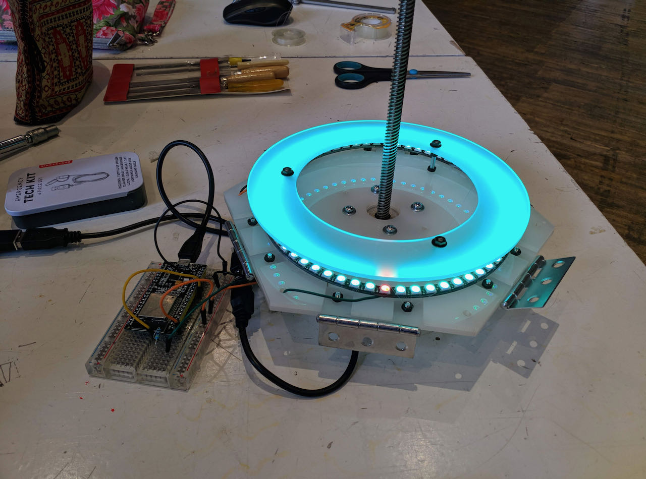
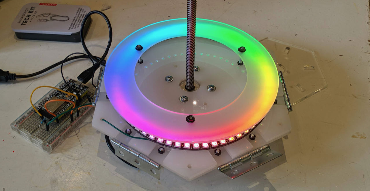
Back at the Waag i connected the computer back to the 60 LED ring and checked the programming i did at home.
This is with 3.3V power on the Neopixels
And this brighter version is when i swtiched to 5V. Hard to see, you will have to take my word for it.
Time to try some of the things i programmed with the 24 ring.
- pastel propeller:
- pink sparkels
void pink_sparkles(){
  for(int i = 0; i< ledCount;i++){
    int shade = random(10,255);
    newR[i] = shade-50;
    newG[i] = shade;
    newB[i] = 255;
  }

  for(int n = 0; n < 256; n++){  //update over time
    for(int i=0;i<ledCount;i++){    //update each pixel
      int thisR = map(n,0,nmax,oldR[i],newR[i]);
      int thisG = map(n,0,nmax,oldG[i],newG[i]);
      int thisB = map(n,0,nmax,oldB[i],newB[i]);
      strip.setPixelColor(i,thisR,thisG,thisB);
    }
    strip.show();
    delay(5);
  }

  for(int i = 0; i< ledCount;i++){
    oldR[i] = newR[i];
    oldG[i] = newG[i];
    oldB[i] = newB[i];
  }
}
//later on i realized that the shade-50 actually brought the value sometimes below zero.
- Rotating leds
void loop() {
Chase(strip.Color(255, 255, 255), 50); // R,G,B, speed
}

void Chase(uint32_t color, int wait) {
// Repeat 10 times...
   for(int a=0; a<10; a++) {
//  'b' counts from 0 to 2...
    for(int b=0; b<3; b++) {
// all pixels off
strip.clear();

// 'c' counts up from 'b' to end of strip in steps of 3...
      for(int c=b; c<strip.numPixels(); c += 3) {
        strip.setPixelColor(c, color); // Set pixel 'c' to value 'color'
      }
      strip.show(); // Update strip with new contents
      delay(wait);  // Pause for a moment
    }
   }
  }
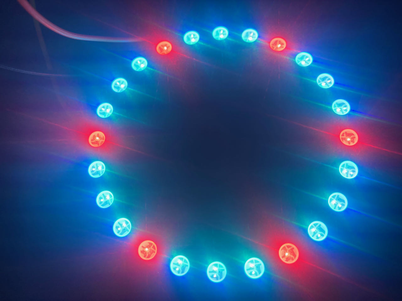
- Reset of the light with the Hexalights
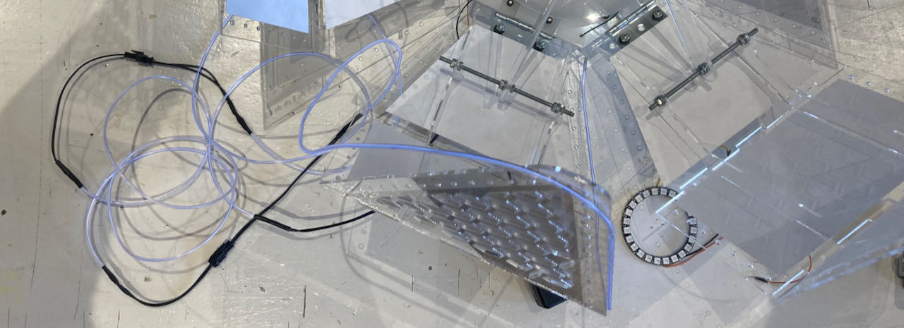
The opening of the flower with the ELwire and some blue LED at the end, just because it looks so magicly.
Elwire continued
Figuring out how to dim ELwire has been a funny journey, so many different ways to solve it or in some cases not working at all :)
The first road i took was the The TRIAC version from 2011 The documentation is very sporadic and in some part contradicting eachother so i decided to try to put a drawing together from what i could find to see if it made any sense.
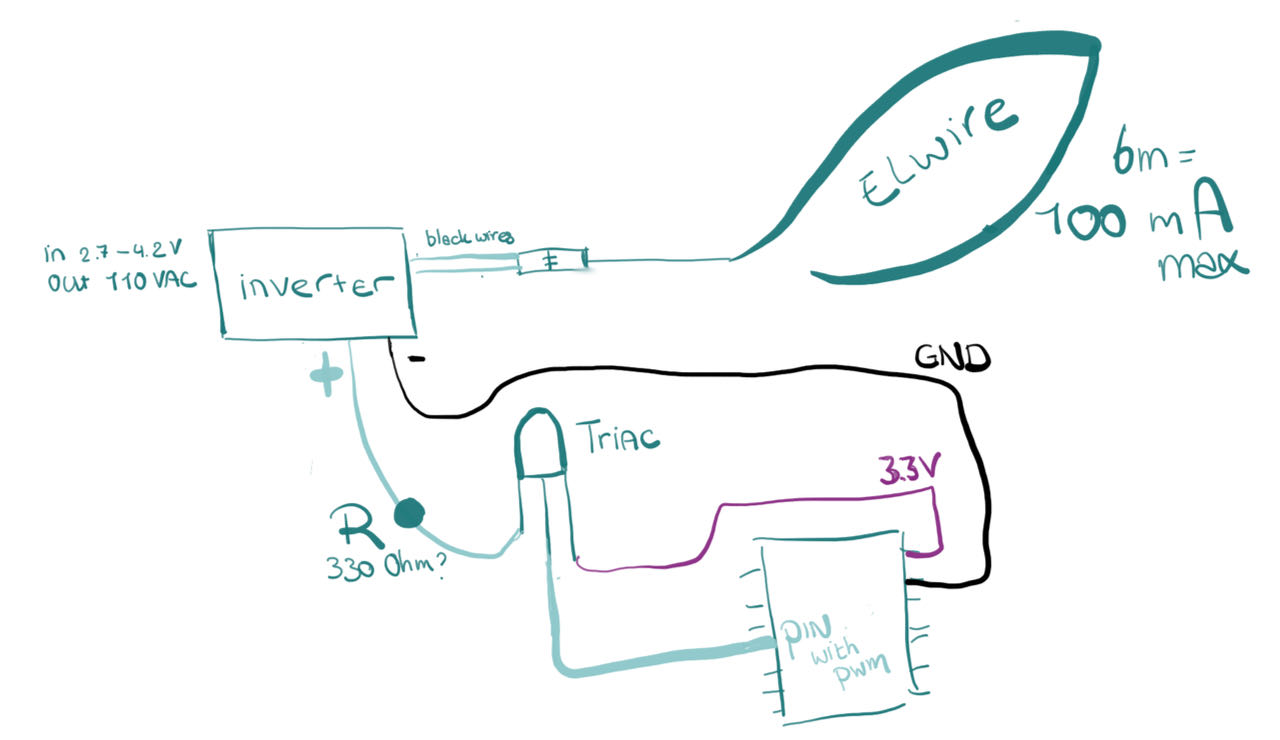
Henk ordered the 3V Elinverter and a TRIAC 600V for me and the 330 Ohm resistor we had in the Waag.
So i put it together as on the schematic and the first try without the TRIAC was fine, the 3V inverter works just fine in combination with 2 AAA battery.
The moment i would put the TRIAC inbetween the intensity of the ELwire would be really a lot less, which is a shame because it seemed that the road via TRIAC was the only way to make it dim instead of just on/off. Which of course i should have taken pictures from but in the heat of the battle thats exactly what i forgot to do.
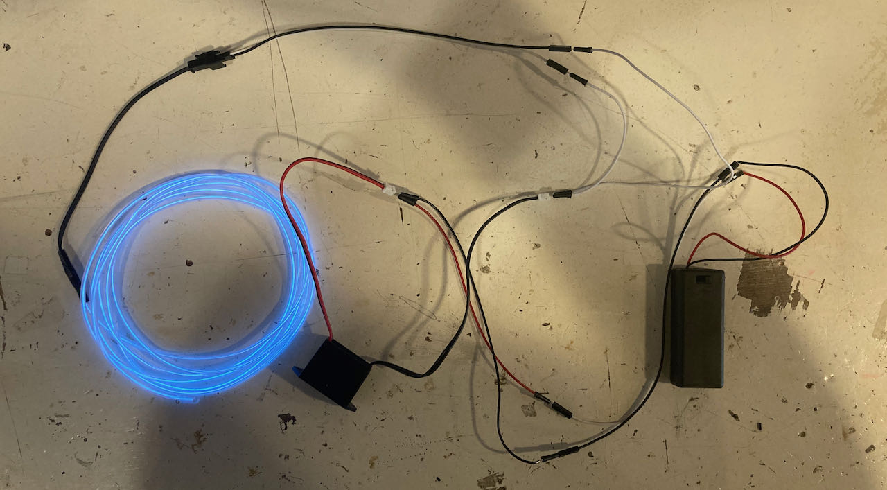
Elwire connected directly to a ElWire inverter works perfectly
The moment i tried to put a resistor in between the intensity of the Elwire would go down. When measuring i realized that not only would the Ampere drop but also the Voltage, measured before the ElWire inverter.
This confused me a lot, still does to be honest.
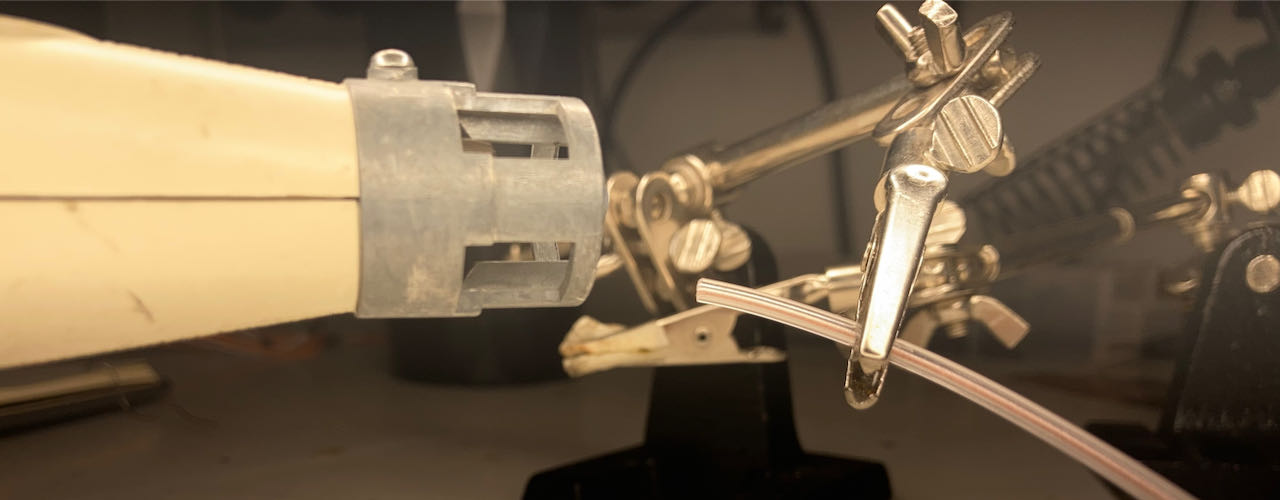
Soldering the ELwire
I was so thankfull there is a good guideline with pictures on line to follow on this site
This information i found on this site helped me a lot:
- remove outer coating about 1cm from the end (it may help to heat the end so its softer)
- if you have the 2 copper wires sticking out you can try to strip the pvc sleeve
- cut a little piece of copper tape
- stick it to the edge of the stripped wire, fold the 2 thin wires on top
- solder the wires to the tape, shortly otherwise the sleeve will melt
- wrap the remaining tape 1 time around to cover and protect the solder points
- scrap the phosfor of the middle wire, half of the wire is fine
- tin the inner wire
- get the external wires, on longer then the other, polarity doesn’t matter.
- put heatshrink on the wire that will be connected to the core
- solder the wire to the inner core
- heat the heatshrink on the bare parts
- solder the other wire on the coppertape
- cover it with heatshrink
So let’s do this:
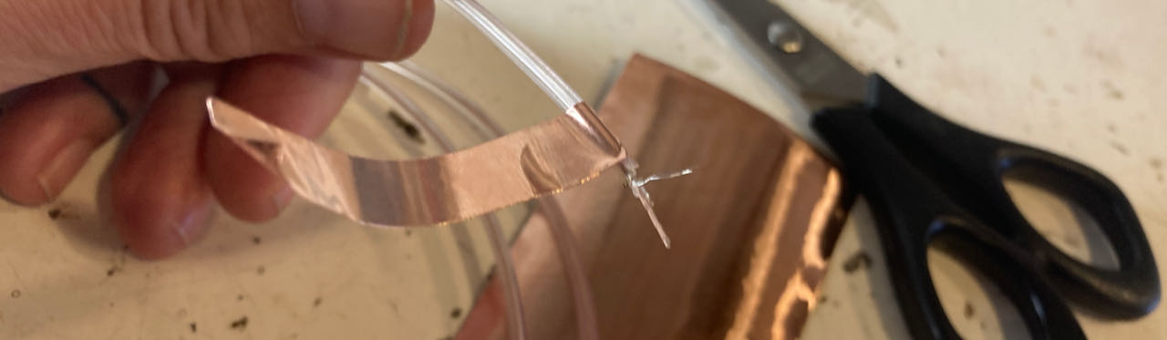
The outerlayer is a bit tricky to get off without damaging the corona cores, with heating it up i managed to do this although it took a bit off time (times 11 since i had to do 6 wires).
Put tape around the wire just behind to how far you took away the plastic.
Solder the corona wires on the coppertape
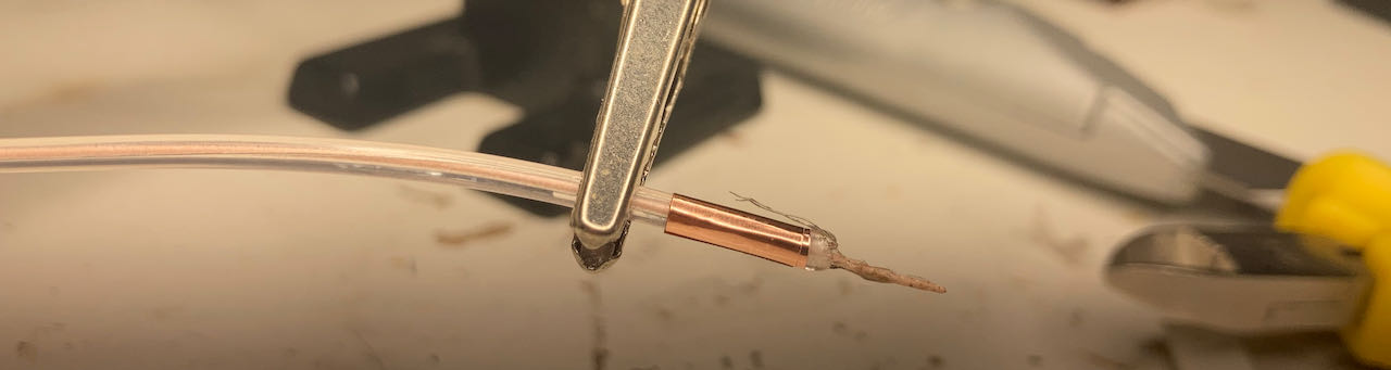
Cover the soldered corona wires with coppertape.
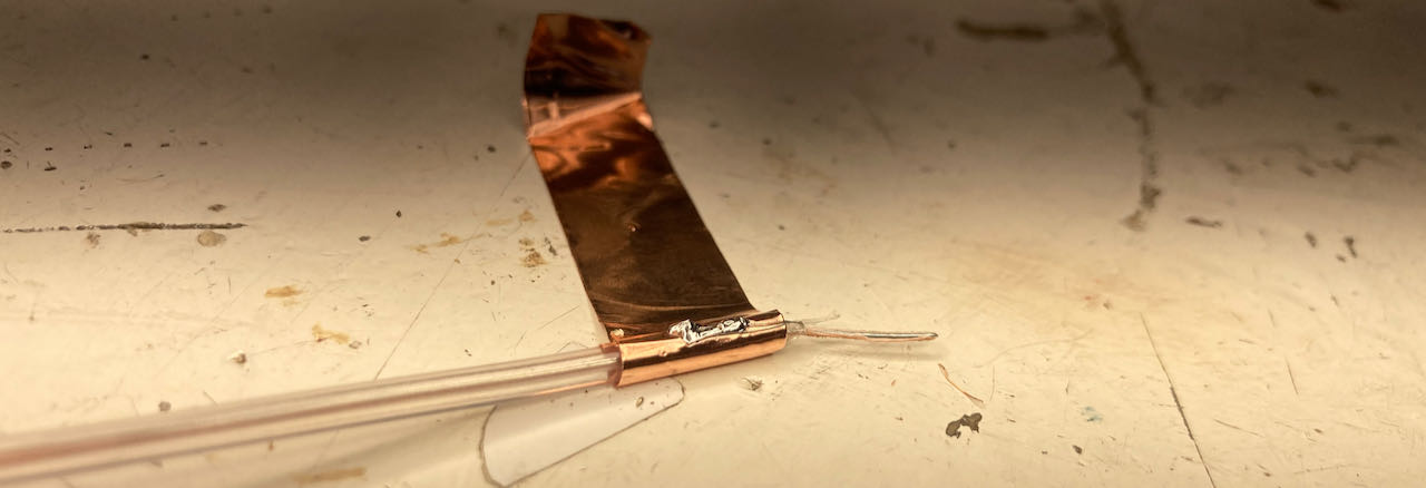
From this point it gets easier.
- scrap the fosfor off the central pin
- solder a wire on it
- put a heatshrink around that part
- solder a wire on the coppertape
- put a heatshrink on the whole connection
always remember to put the heatshrink around it before soldering :)
I put all the plugs i had from the original inverters that come with the Elwire on there and for the rest i had to connect them directly since there were no connections available in the Waag.
Making the ELwire blink (gave up on fading)
This was another version i found online but the documentation was impossible, not enough information for me to follow what was happening but decided to give it a go anyway.
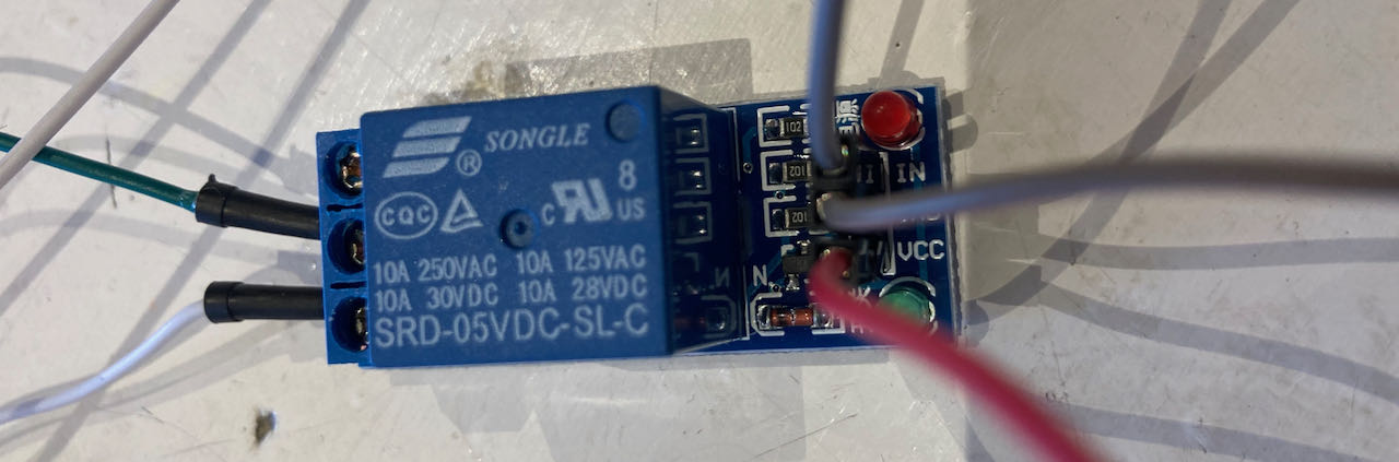
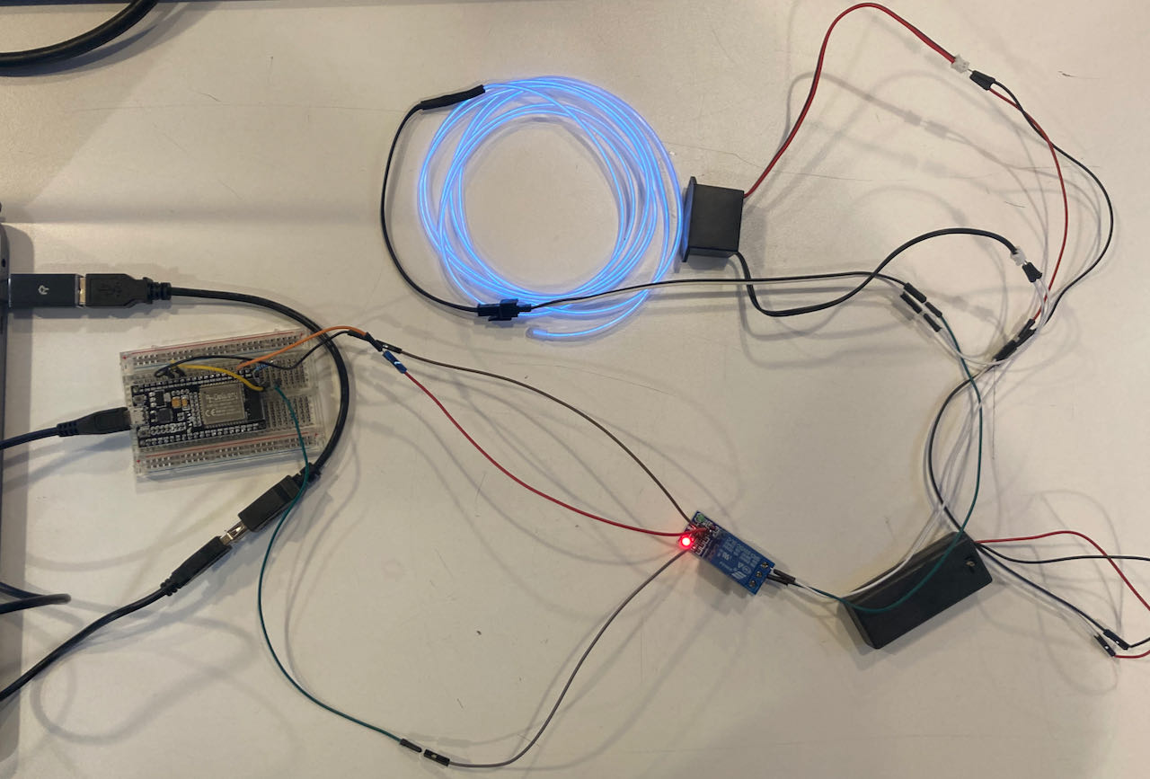
Henk found a working relay in his personal storage (the one we originally tried it with was broken)
I put together a schematic based on the information i had at that time.. i was under the understanding that i would need a 330 Ohm resistor in the data line but it turned out i made the mistake of copying not understanding. Luckily enough the 5V relay would still flip.
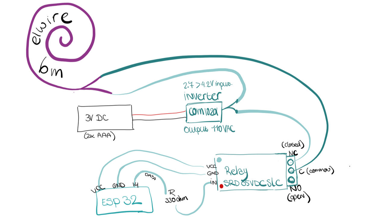
The relay has on one side
- VCC
- GND
- Signal in
The other side has
- NC (normally closed)
- Common (the part that moves from NC to NO)
- NO (normally open)
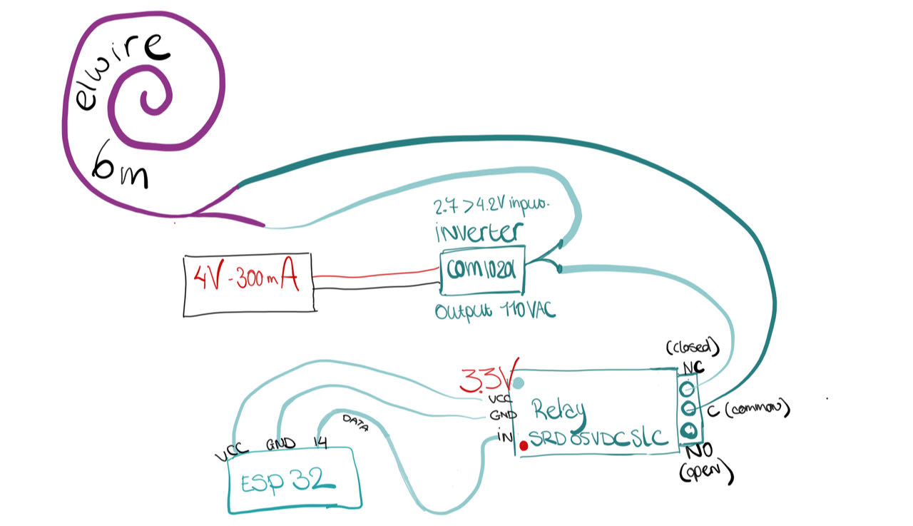
I only realized later that the 5W relay should accualy be on a 3.3VC not on 5V as i assumed. 5V refers to the signal voltage it needs to flip.
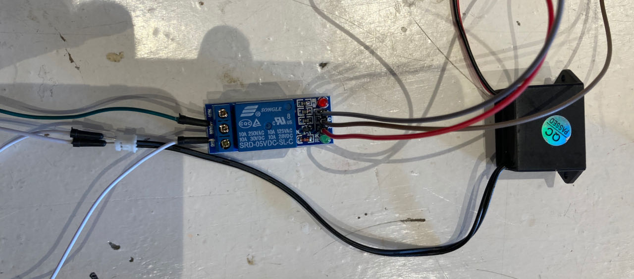
So this the schematic on how i made it finally work.
later in the process the ESP32 would be replaced with an Arduino but that doesn’t really matter for the schematic.
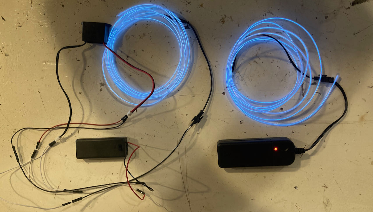
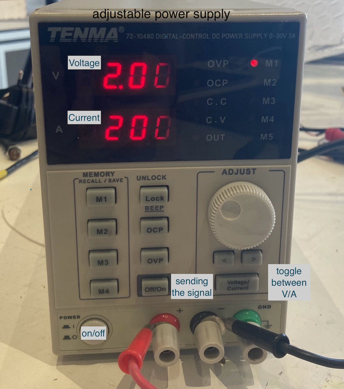
So finally got it all working but still with a 3V batterij to power the inverter. Time to try to get the Elwire to glow at their full potential, what i knew from the datasheet that it accepts from 2.7-4.2V input but the Current took a bit more googling and trying out. We started at 50mA the with steps of 50mA increased till it made the high frequenty sound so recognizable for ELwire. (wiki tells me its corresponding to the frequency of the oscillator))
- Voltage: 4V
- Ampere: 300mA
disclaimer: the voltage on the picture is not what i used, it’s just an explanation on an adjustable power supply.
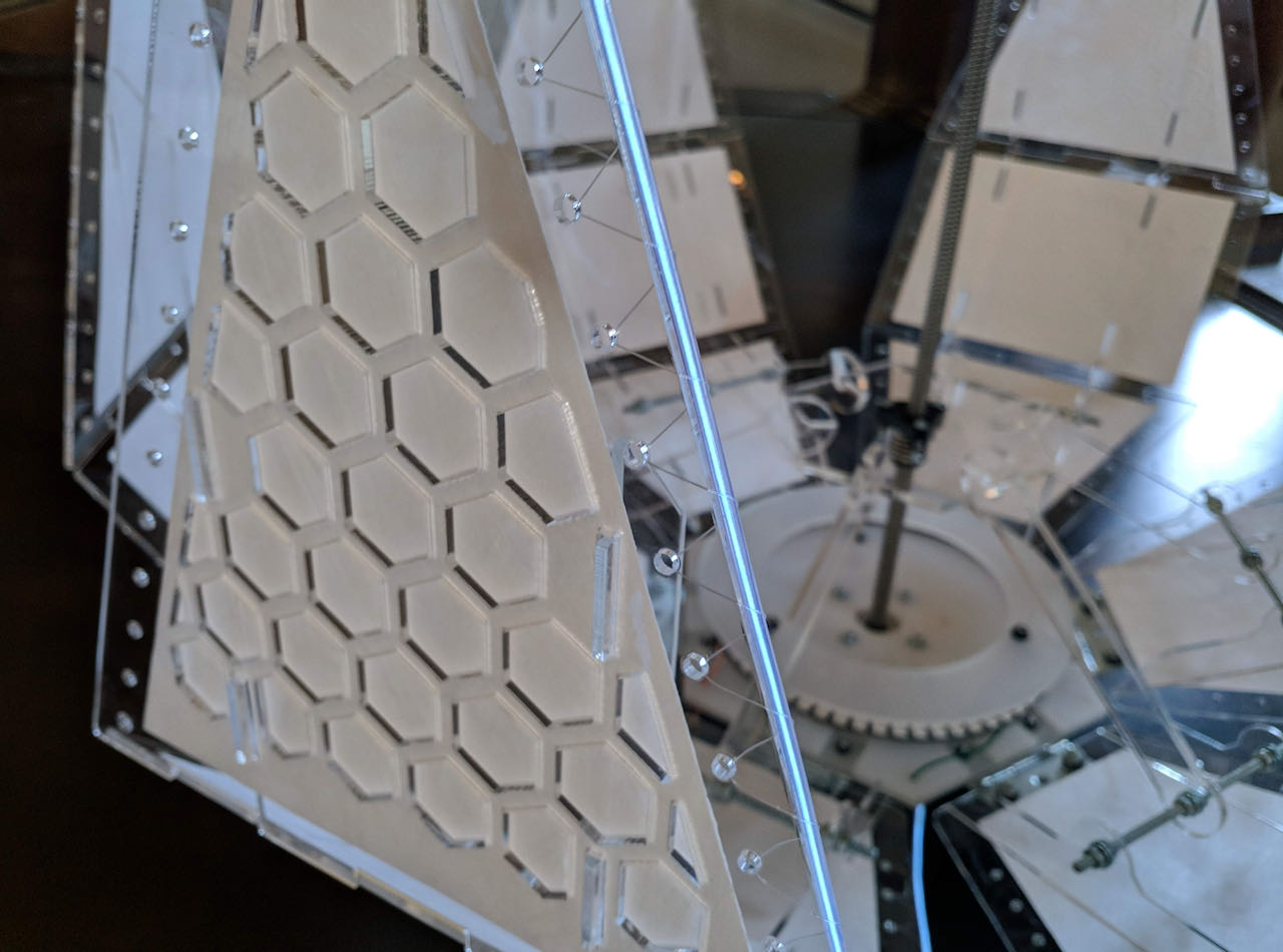
detail picture of the Elwire on flo.
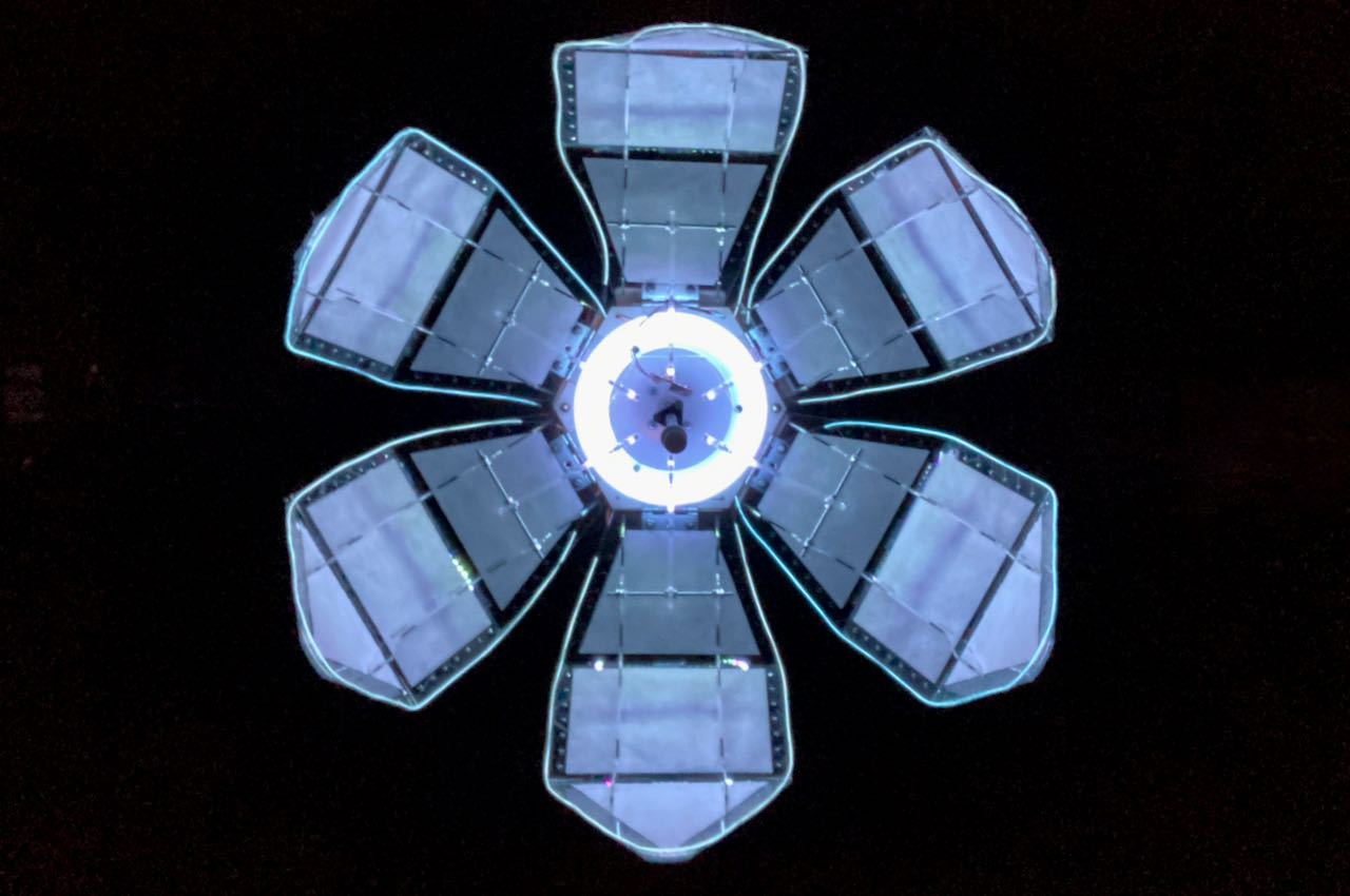
elwire hero shot!
- had a lot of fun, learned a lot, wished i could have been more helpfull on programming the overall thing the last day, but maybe the troubleshooter role is more my comfortzone.
 - just use a 10m ELwire and tape the parts that should not lit black and focus more on making it dimable.
- I would like to spend time to make the other research i’ve done for this project, the Astera bulb with CRMX and try to make a tungsten bulb dim.