Computer-Controlled-Cutting
Operating CNC cutting machines
Intro:
Welcome to my third week of Fabacademy. In this week I will learn about Computer Controlled cutting using laser cutting / engravering machine and vinylcutter.
Week Task:
Group assignment: characterize your lasercutter's focus, power, speed, rate, kerf, joint
clearance and types
Individual assignment: cut something on the vinylcutter design, lasercut, and document a parametric construction kit, accounting for the lasercutter kerf,which can be assembled in multiple ways, and for extra credit include elements that aren't flat
Group assignment: summary
We in group done various experiment to calculate Kerf value (thickness of a stroke get dissolved while cutting materials) and minimum thickness that can be achieve through our CNC laser Cutter on different materials, This collected data is helpful for each of us in our individual work with our CNC lasercutter. Since once you have Kerf value you can modify your model accordingly to achieve maximum accuracy. Click here to know more...
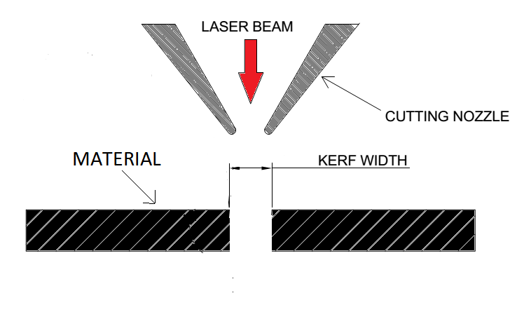
kerf width calculation
Here I took 3mm cardboard to work on. I found it required high speed and little less power to cut well and if cardboard is multi layer than number of pass to given is equal to number of layer it have. This is my idea and It worked well specially for thick many layered cardboard
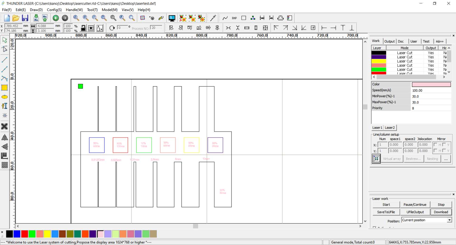
So I made this general design in group assignment part to check kerf and to check how material response to different power and speed. For default speed and power I refer manual where it given
.jpg)
Recorded Kerf of Comb (On Default Power 65 % and Speed 50 mm/s)
| Part Thickness | Kerf (Part thickness - Part thickness after cut)/4 |
|---|---|
| 10mm. | 0.18mm |
| 5mm. | 0.17mm |
| 2.5mm. | 0.15mm |
| 1.25mm. | 0.18mm |
| 0.625. | Burned |
| 0.3125. | Burned |
From experiment it seem kerf value range from 0.15 to 0.18 mm. Part thickness less than approx. 1 mm get completely dissolved or burned.
Different Speed and power test was failed so default given power and speed for cardboard work best
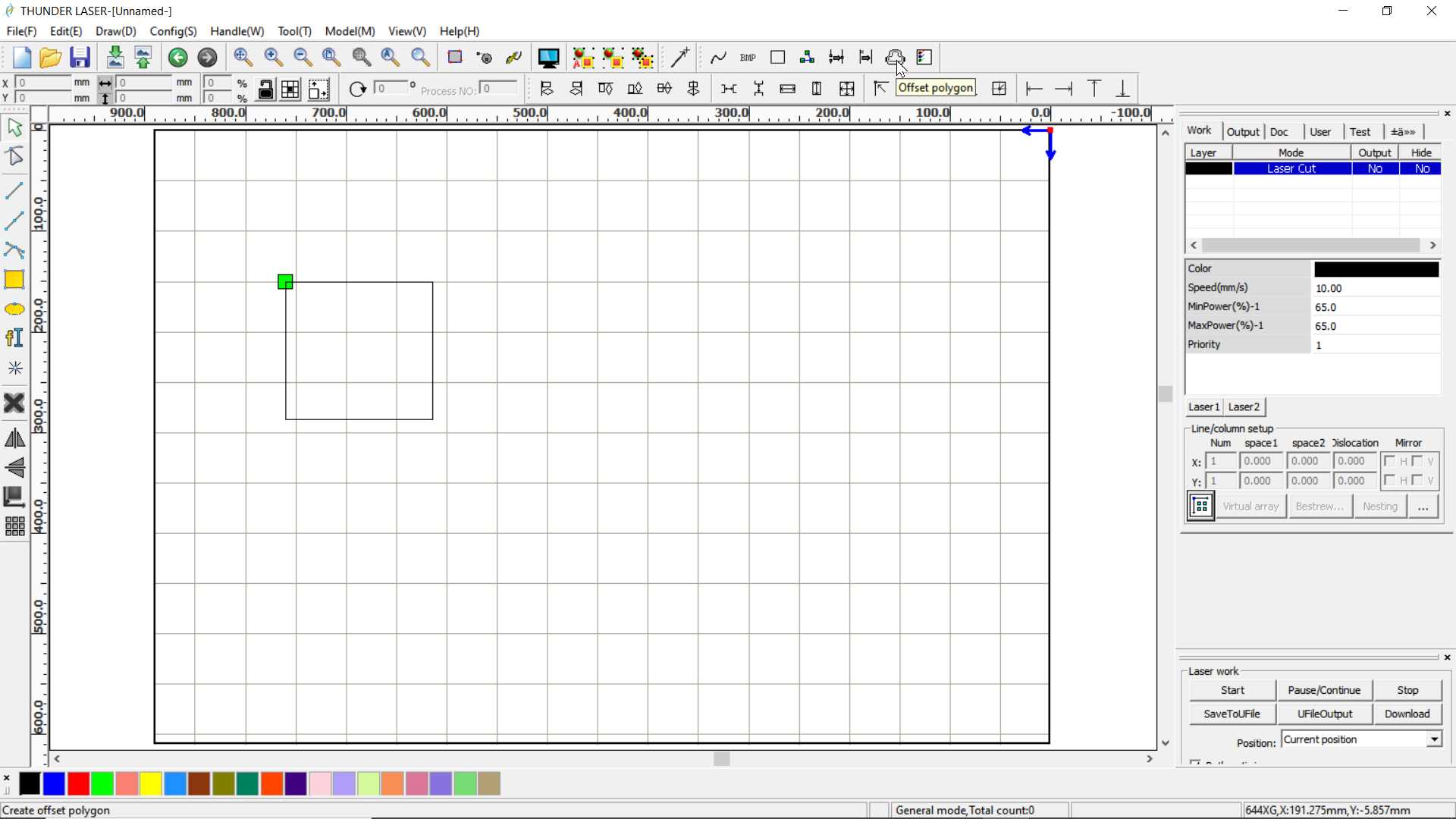
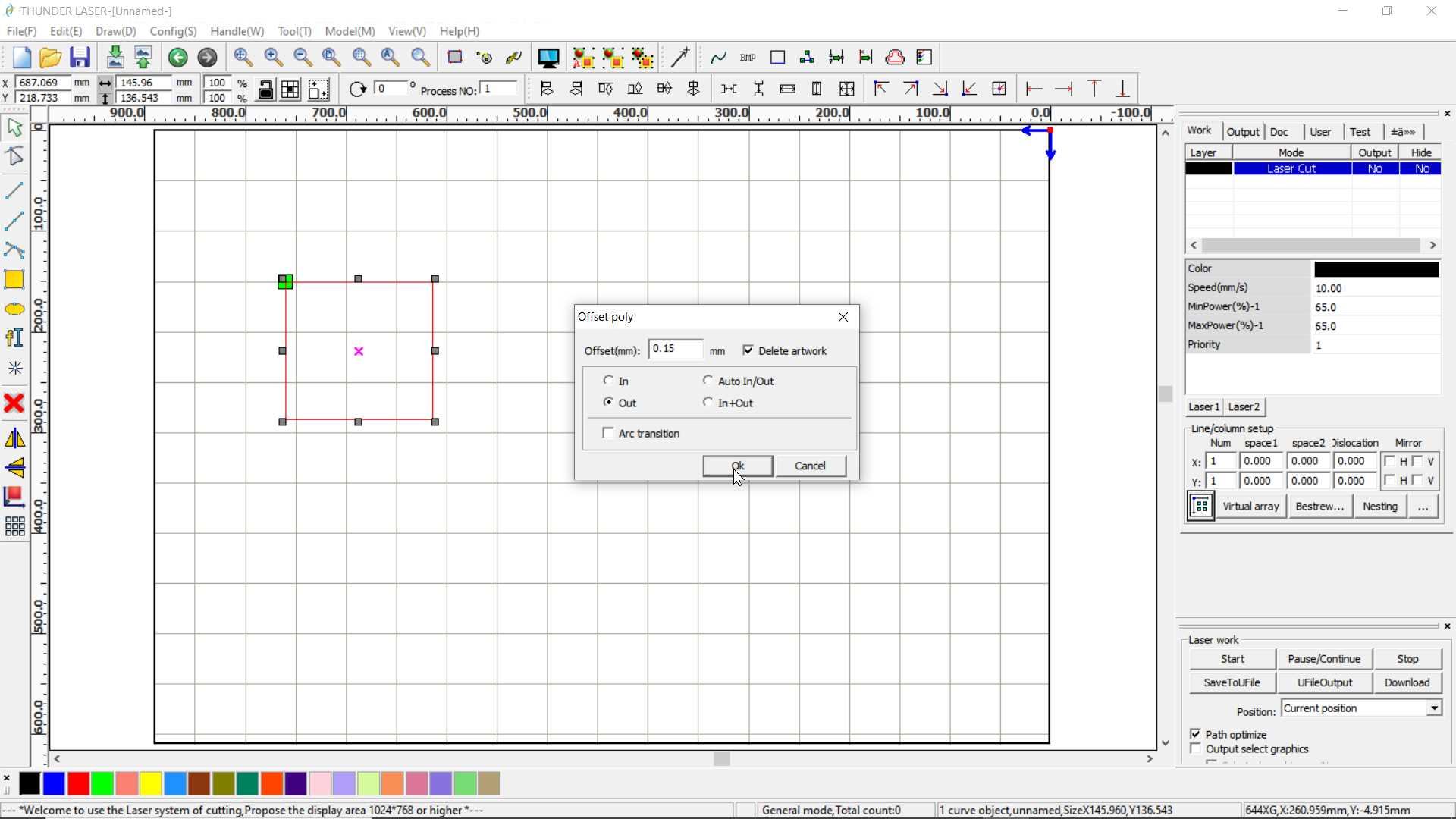
There is one way to add kerf value in RDwork using option offset polygon. This is good when you dont want to modify orginal design
Individual assignment:
What is 2D, 2.5D and 3D cutting machine?
2D cutting machine cut 2d shapes that are all at the same depth. Where in 2.5D machine you can cut your 2d drawing and can adjust z axis accordingly to you materials thickness. where In 3D machine you have complete control on all three axis and can cut 3D design on it.
What is Laser?
A laser is a device that emits light through a process of optical amplification based on the stimulated emission of electromagnetic radiation. The term "laser" originated as an acronym for "light amplification by stimulated emission of radiation".wikipedia
/CO2 laser
The carbon dioxide laser (CO2 laser) was one of the earliest gas lasers to be developed and is still one of the most useful types of laser. Carbon dioxide lasers are the highest-power continuous wave lasers that are currently available. They are also quite efficient: the ratio of output power to pump power can be as large as 20%. The CO2 laser produces a beam of infrared light with the principal wavelength bands centering on 9.6 and 10.6 micrometers (μm).wikipedia
CO2 lasercutter
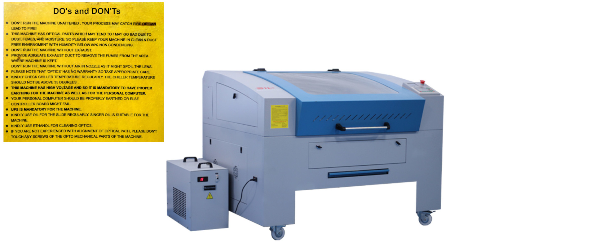
This lasercutter in 2.5D cutting machine having 600 x 900 mm working area. Safety in very important with this kind of machines because It involve intense heat and high power that can cause big damage to it surrounding if become unstable. So use it under proper guideline.
.jpg)
.jpg)
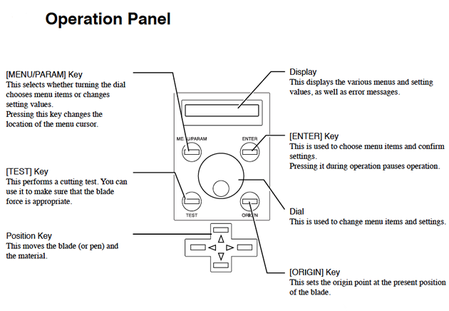
There are some key's and switches on machine to control it. It is CNC machine so you don't need to do cutting job manually. Like in first image down there some switches to turn on and off feature like exhaust, lamp and laser as required and usb port and connector to connect machine with computer. On other side there is image of display and keys interface situated on top of machine use for setting origin and for loading file in it etc.
.jpg)
.jpg)
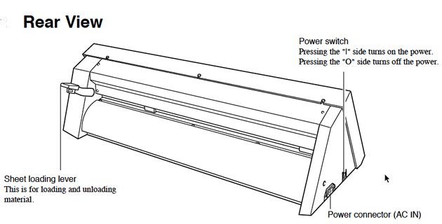
CO2 laser tube is placed back of machine safe from user contact. Laser travel out in working area through arrangement of lens and mirrors and get into nozzle where it get focus on material to cut it through. Nozzle simultaneously provide compressed air that support laser while cutting. As material ant it thickness vary the laser power and speed have to set accordingly to get job done. Some standard are given on user manual.
.jpg)
.jpg)
.jpg)
I have Exhaust pipe because while cutting materials it give out fumes which maybe toxic and disgusting needed to throw out else it will get collect in closed room/lab.
Supported Software
RDWork is the software that I have used with this lasercutter to generate file that machine needed. It take design in DXF file and generate rd file that machine understand.
Parametric modelling:
In this assignment I used freecad and Autodesk Inventor for parametric CAD designing. Modeling using parameters is called parametric designing. The benifit of parametric designing is that one can anytime modify the design by just changing parameters and if there is constrait or relation then whole model can be modify with just modifying one or few parameters. Design will adjust itself accordingly hence no need to design it again.
Interlocking design
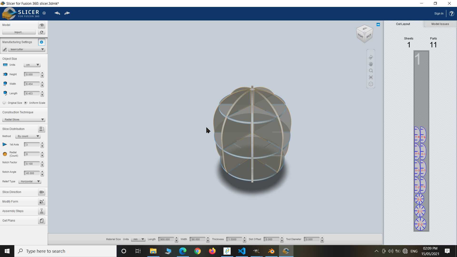
So very first experiment I plan to do to explore software called slicer for Autodesk fusion 360. It is no longer supported by autodesk but still you can download and install it on your system. I have window 10 and I work well in it. It make making of Interlocking design easy compare to manually designing.
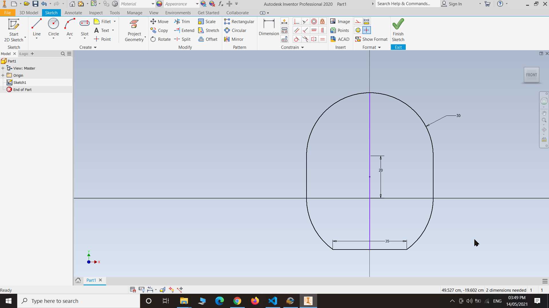
So here I started with making simple shape in inventor not in fusion 360. You can design any shape in any software just one thing at last you need to save it in stl file or obj file because they are the supported on slicer.
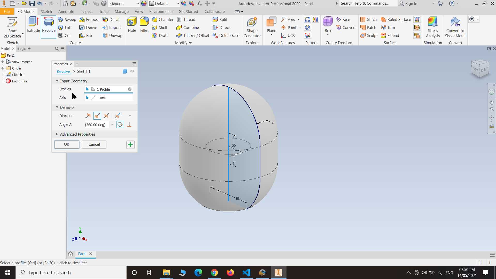
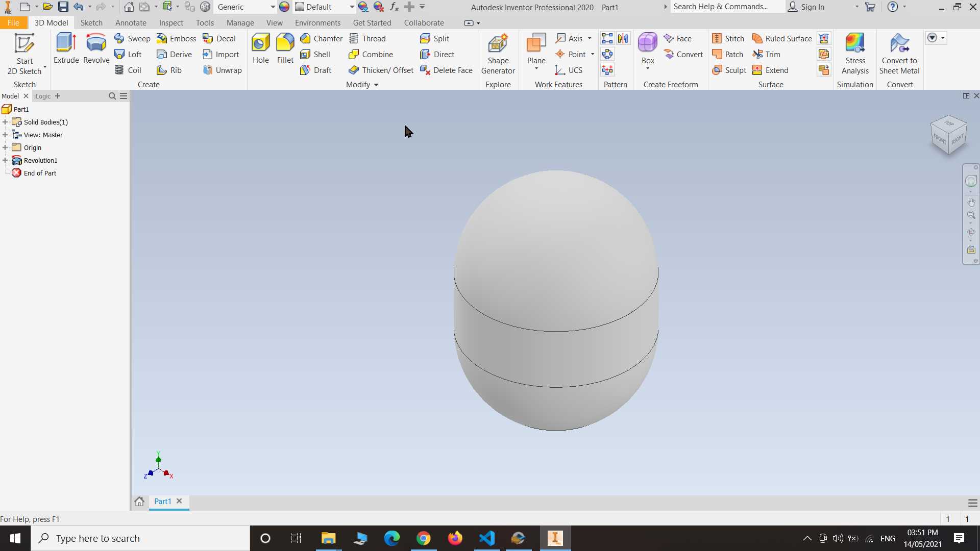
Made sketch first and using revolve tool I made shape look like this...
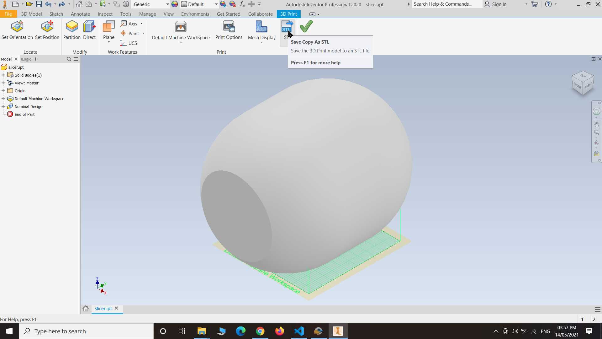
To export my design in stl file I turned on 3d printer option in inventor where I found option to save file in stl.
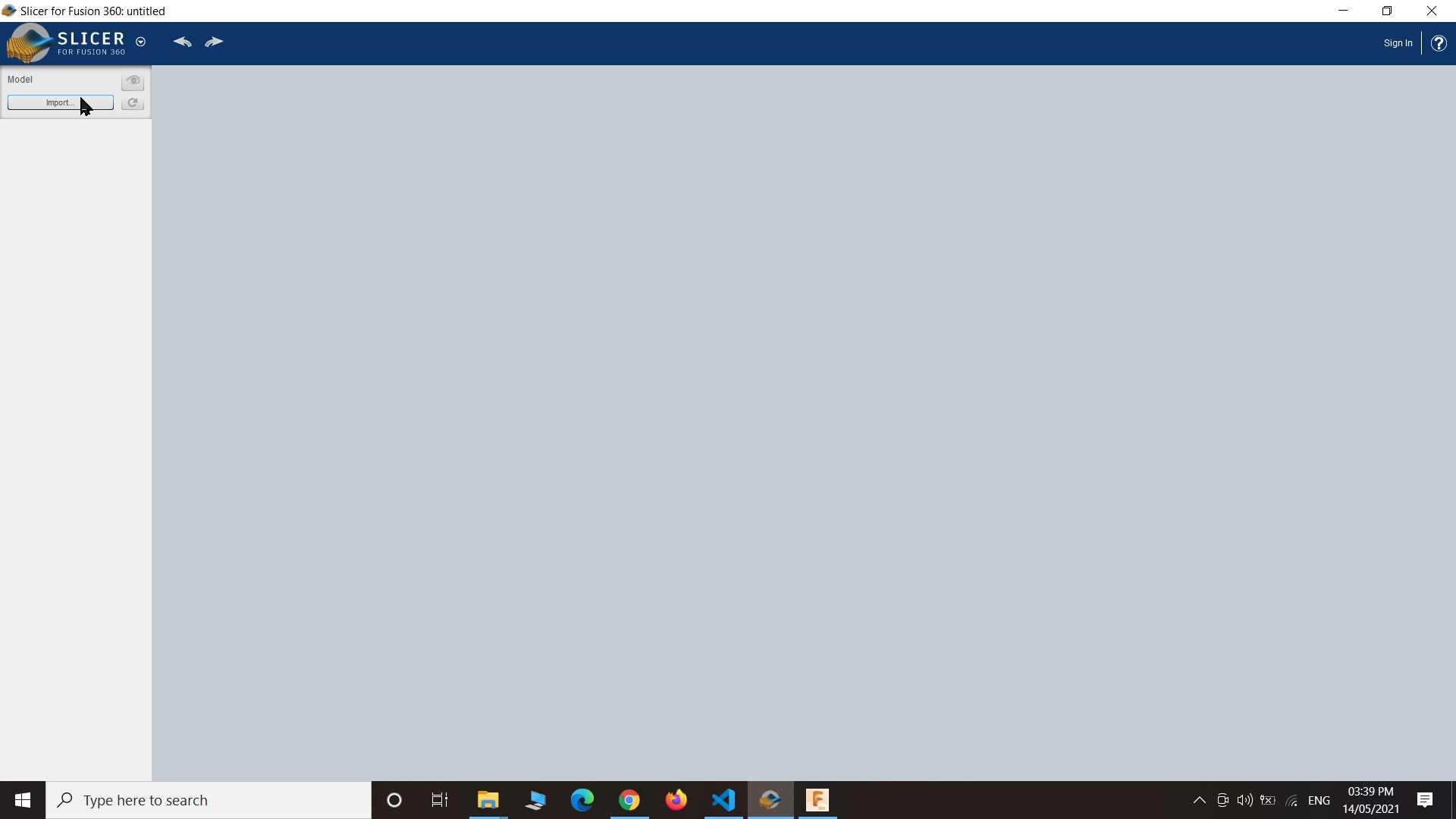
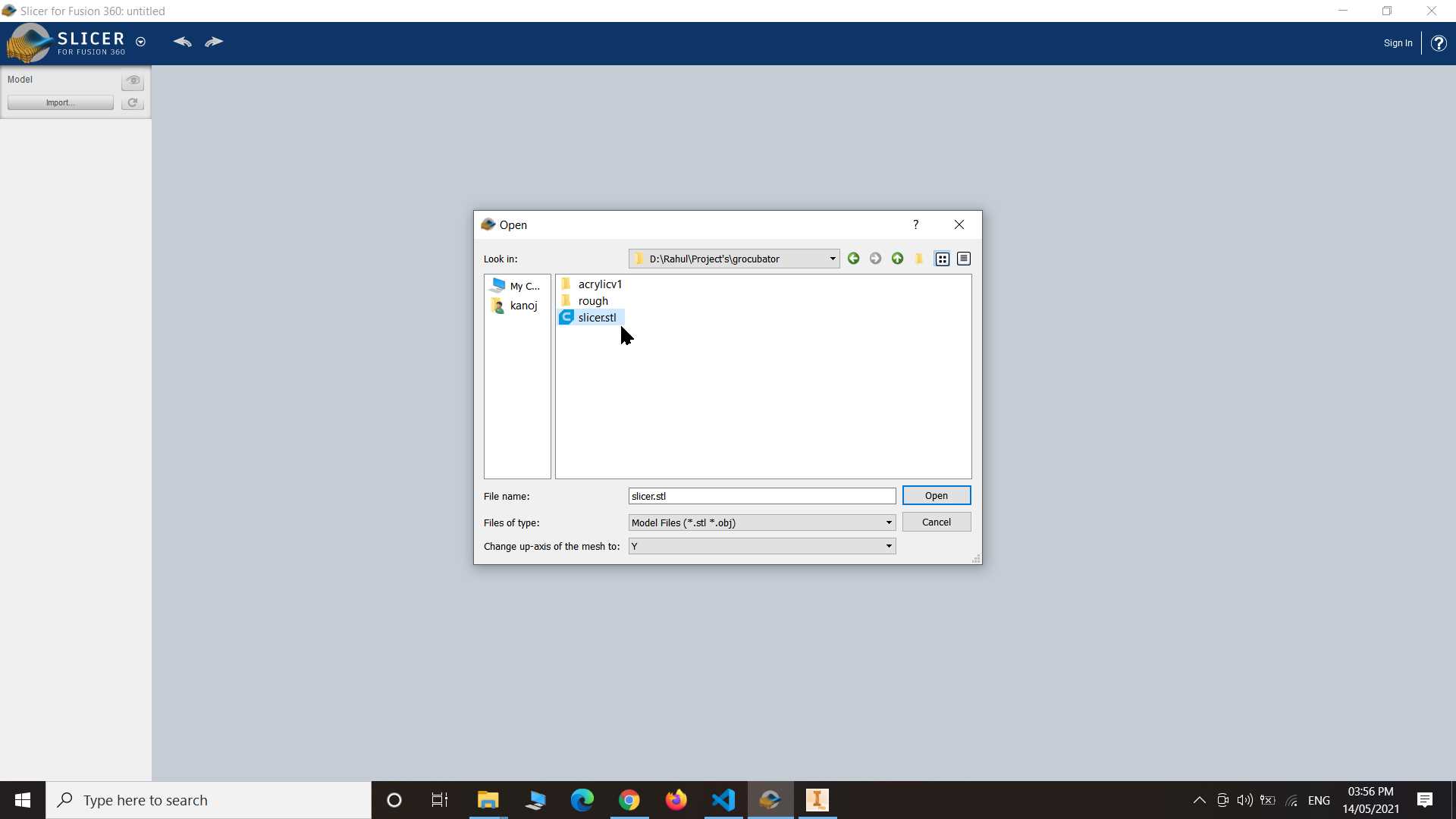
After saving design in stl file and opened the slicer application and imported stl file in it as you seen on images
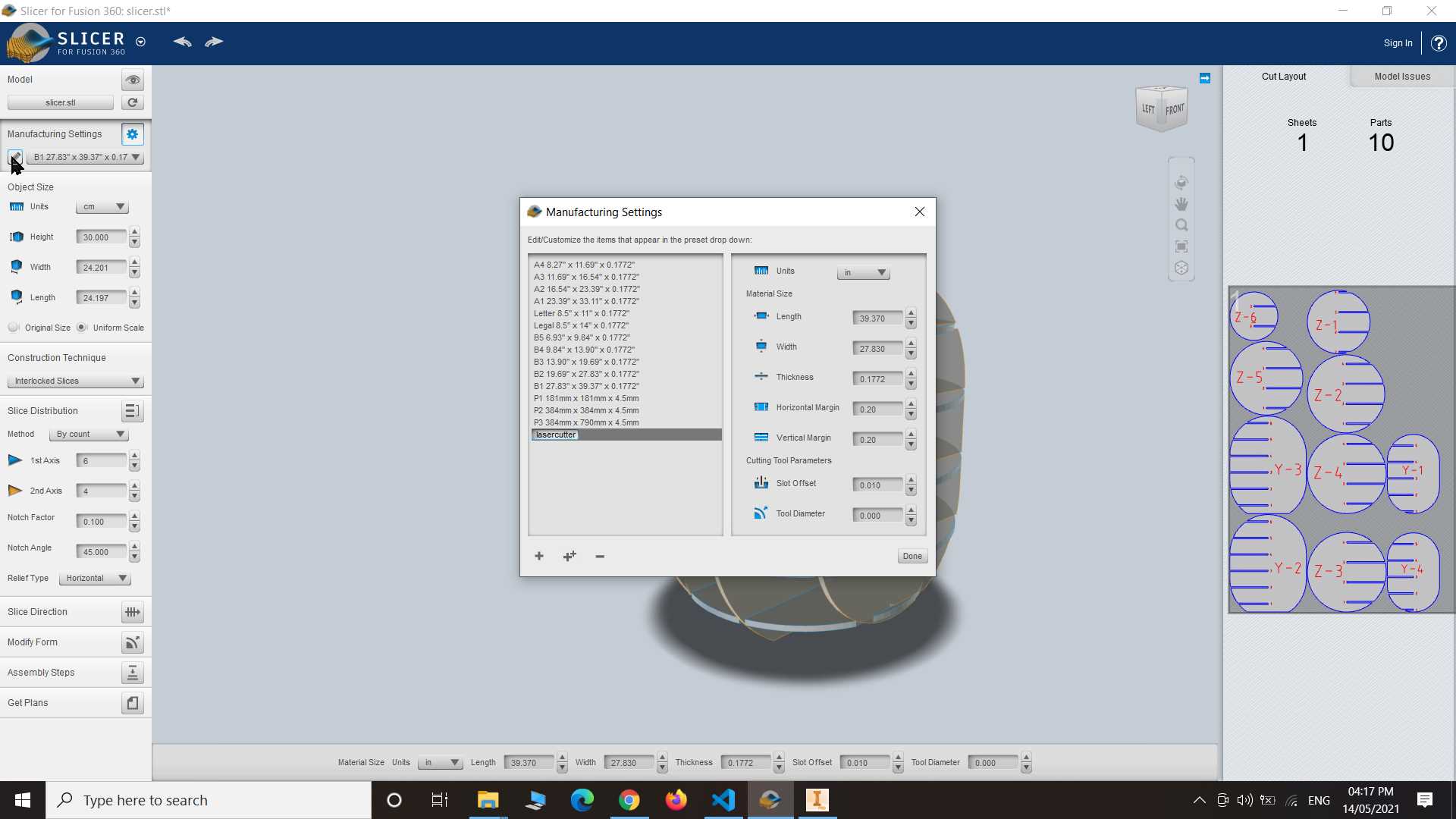
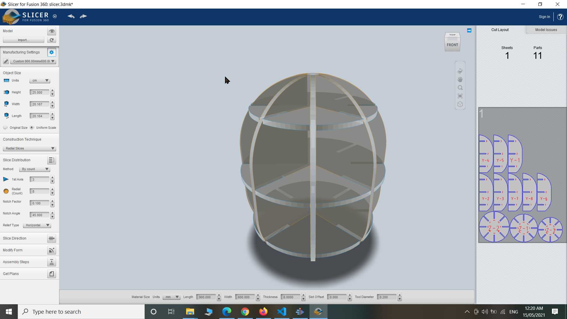
So down here as you see I played with all option to know what does what and Since laser cutter bed size is 900 x 600 mm and my cardboard sheet is of same size so I modified in Manufacturing Setting so that all my design fit in one page.
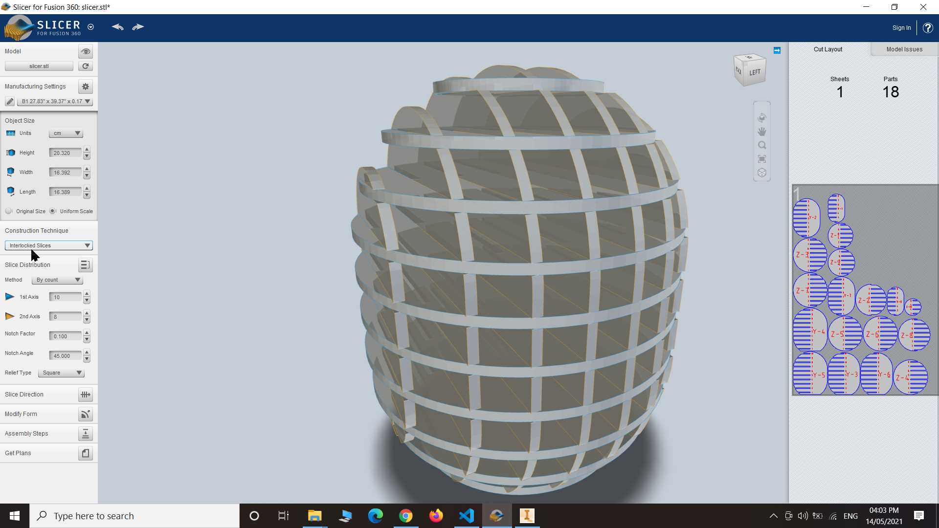
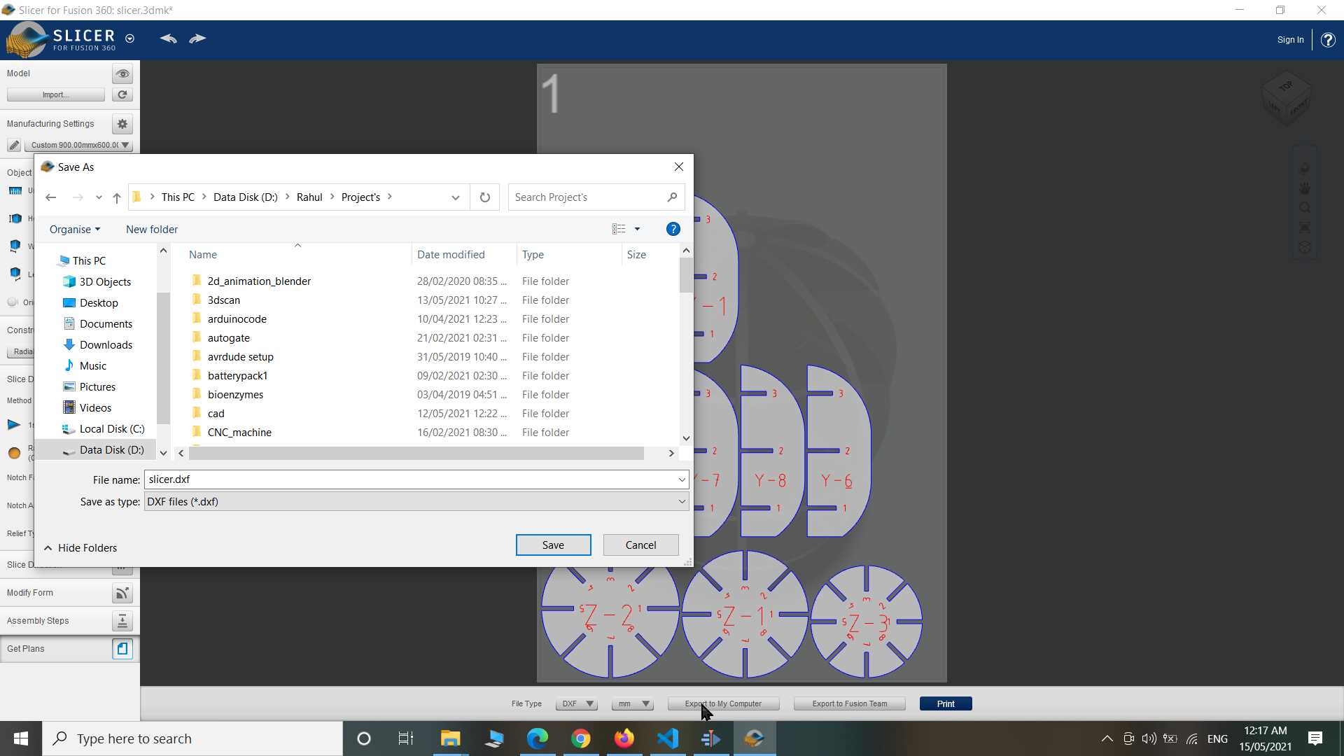
So In construction Setting I like radial slices option after minor adjustment I save the 2d design in DXF file...
This is animation of assembly this going to look this after cutting.
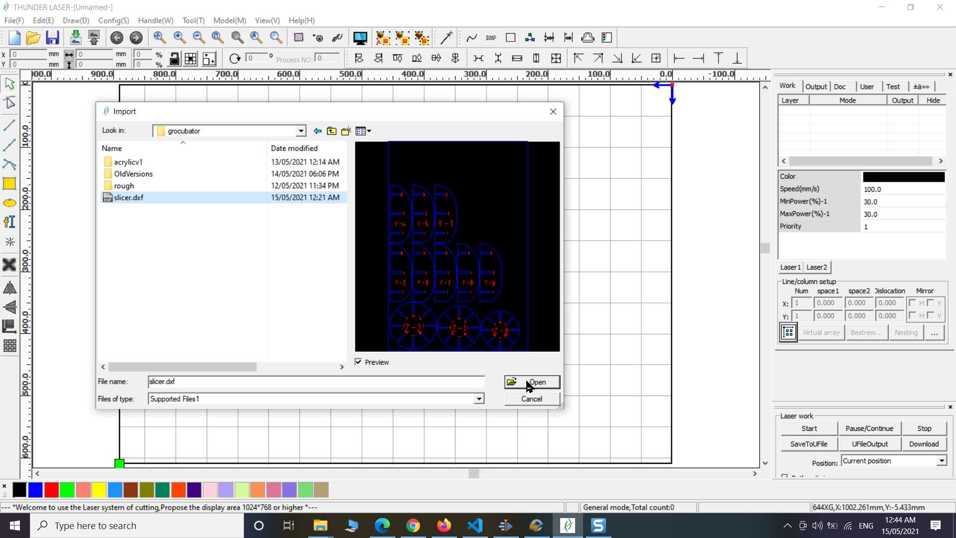
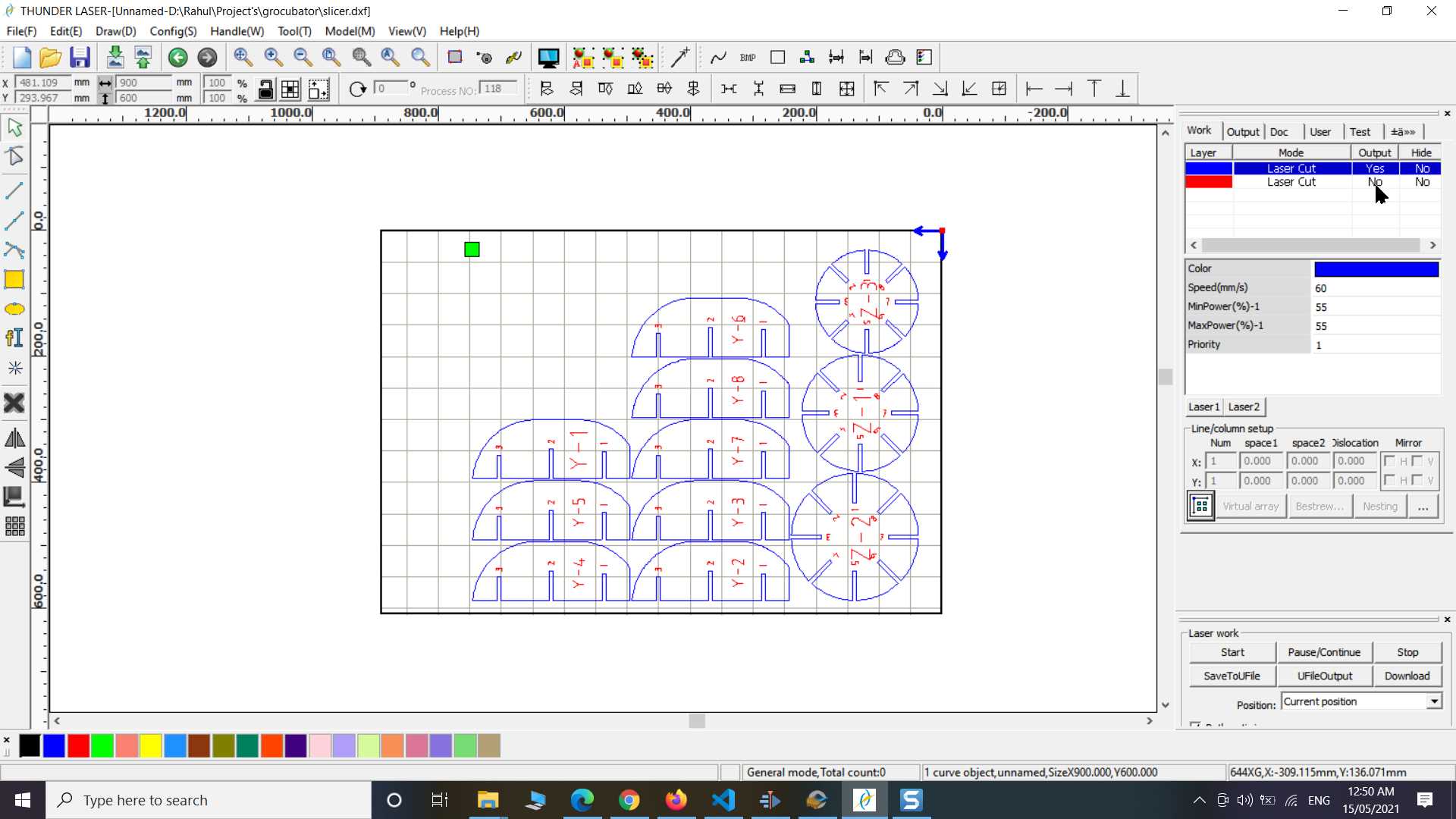
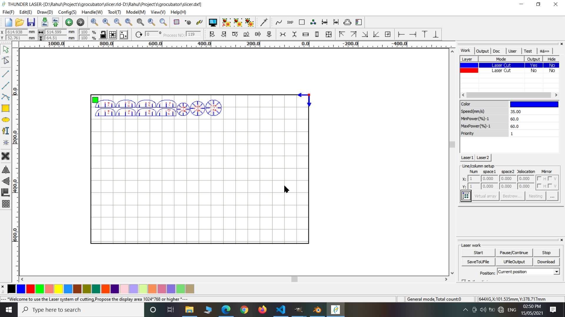
Imported DXF file into RDwork and adjusted it position and power & speed to send it for cutting
So this design is very big for now so I felt not to use large sheet for this and so I edited it reduced it size little bit and laser cut it. I got small MDF piece so I used that this time
.jpg)
After completing all this I have connected my laptop with a machine and using download option on rdwork uploaded my design in machine directly. after that using machine interface I set the origin and checked for frame to confirm how much area cutting design will take. last after confirmation I turned exhaust on and laser on using switches on other side of machine and started the cutting process
After that I assembled all pieced and that how it look
.jpg)
.jpg)
Small thing look even better !
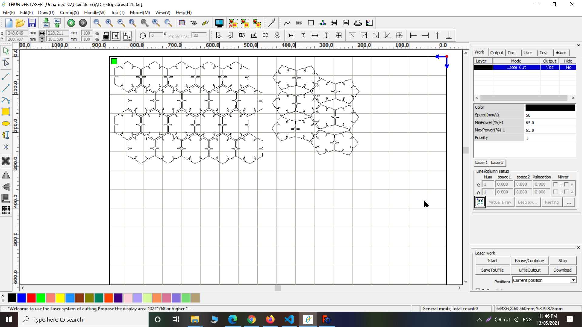
PressFit Kit
So to practice design possiblities with laser cutter we have task to build PressFit construction kit. Pressfit mean joining two shape or part without glue with just notches made on parts. So you can make toy for anyone to who like to play with it or you can be use it for engineering purpose that all depends on need.
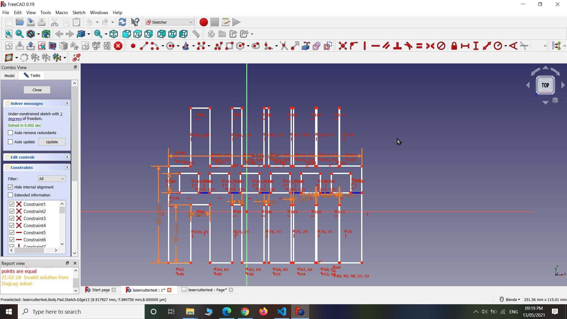
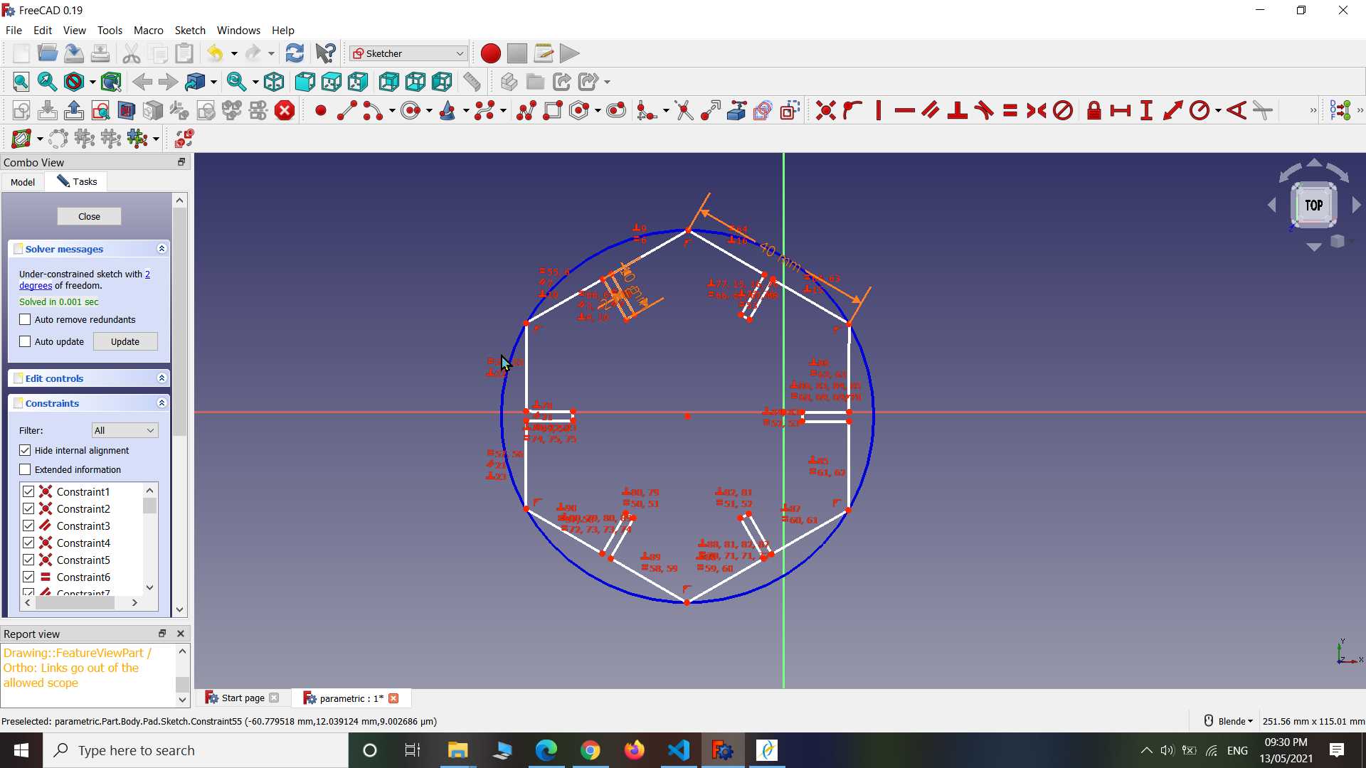
So here will have to do parametric design because to get proper PressFit notches we need consider kerf value later in design without getting into designing whole part again.
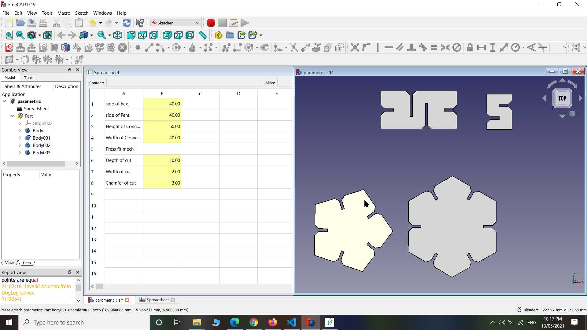
So This is quick review of what I have done. I designed whole PressFit construction kit in freecad, starting with sketching, making parameters list on spreadsheet and finally connecting that with my sketch and model. now when I do change on sheet change will reflect to model as well.
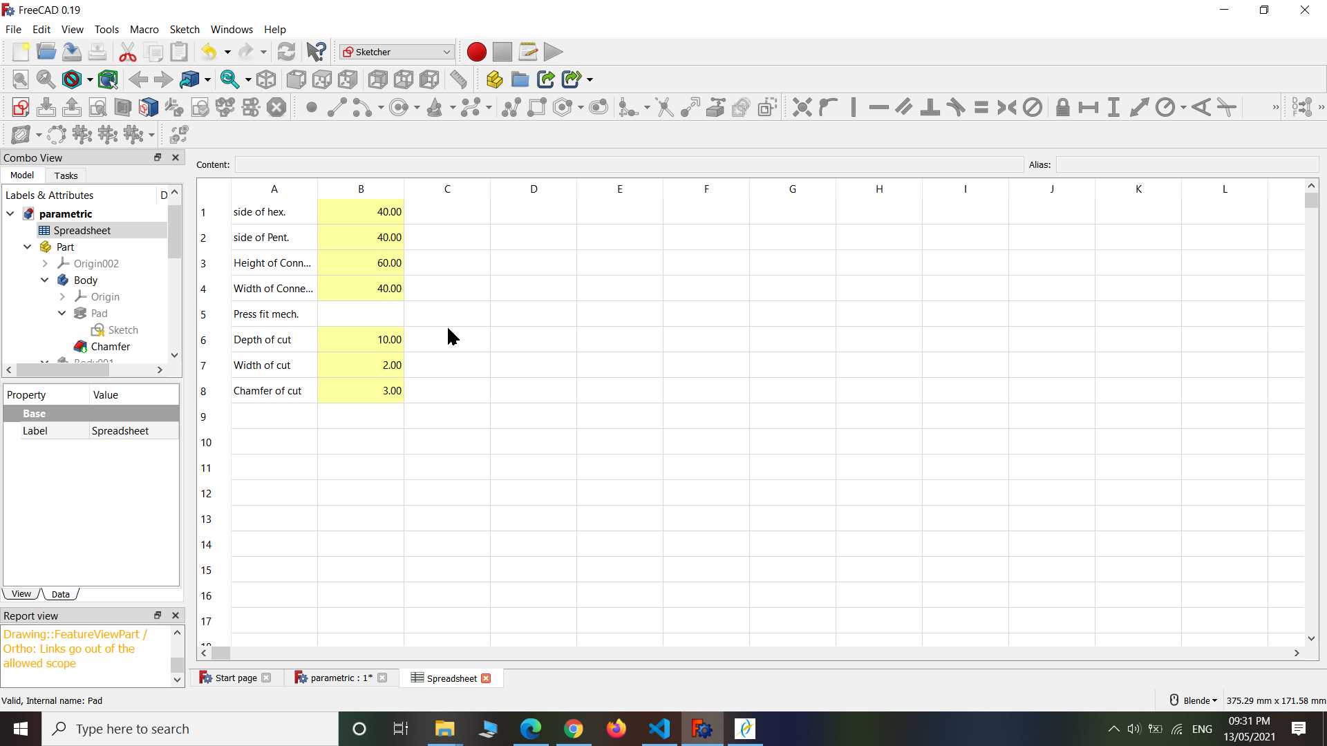
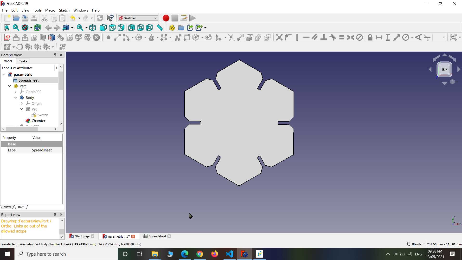
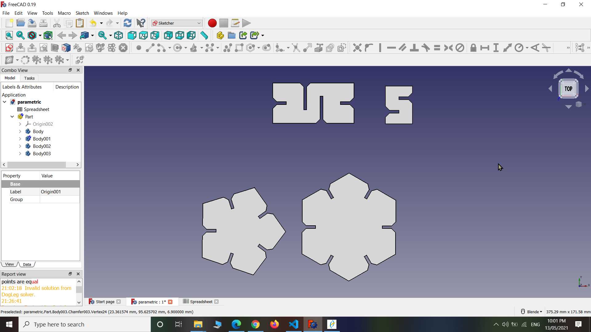
In same way in designed multiple shape and connected them with already made spreadsheet without any change. now all model sharing same parameters for same feature like notches so when I modify something change will reflect on all parts. This good way of designing called parametric design and It useful when your design get regular updates.
After completing the all design I exported them into .dxf file and imported it in RDWork to generate file that machine understand. Here in RDWork I duplicate same shape multiple time because I need to cut off as many of them, I repeated same idea second for remaining shapes and after all that in started cutting on lasercutter
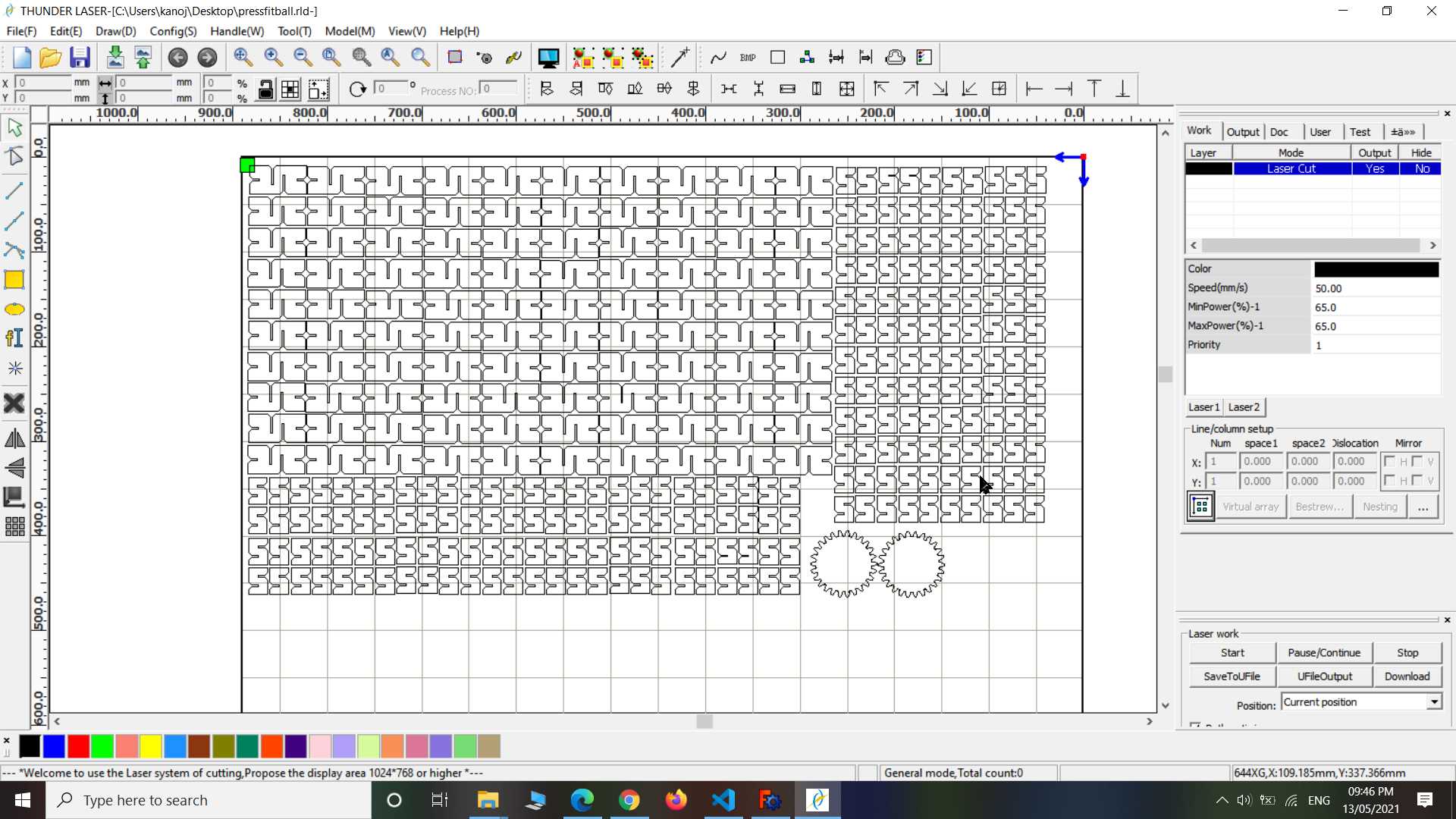
.jpg)
Here that second sheet to get cut.
.jpg)
.jpg)
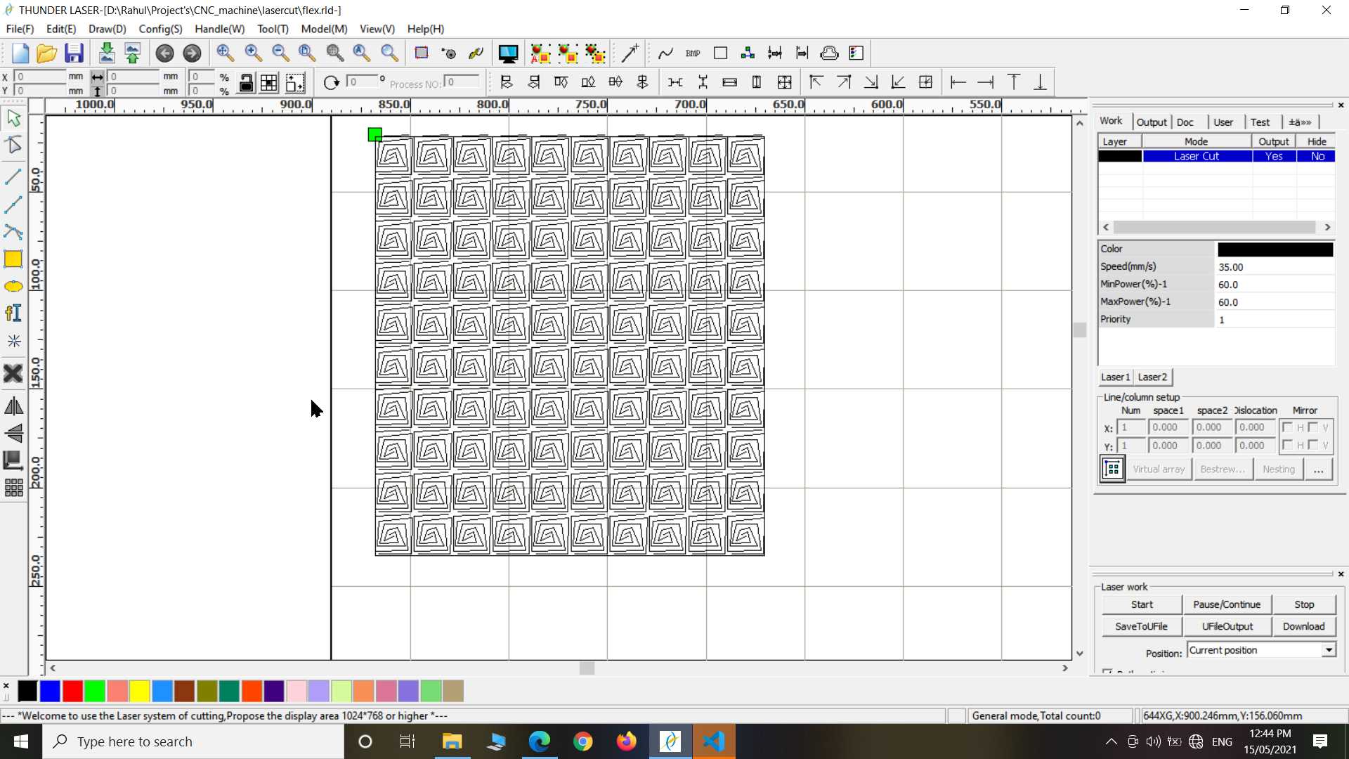
Flex Pattern
So Here I going to use MDF sheet in this experiment. MDF is hard sheet not that flexible but there are many way to make it flexible. One I will try here is cutting some pattern on MDF sheet that help it to become flexible. You can try this with acrylic or metal sheet it work there well too.
So here I made simple repeating pattern on inkscape just only thing you need to make sure this in your design everthing is connected in loop else after cutting pattern with get cut off from your other designs
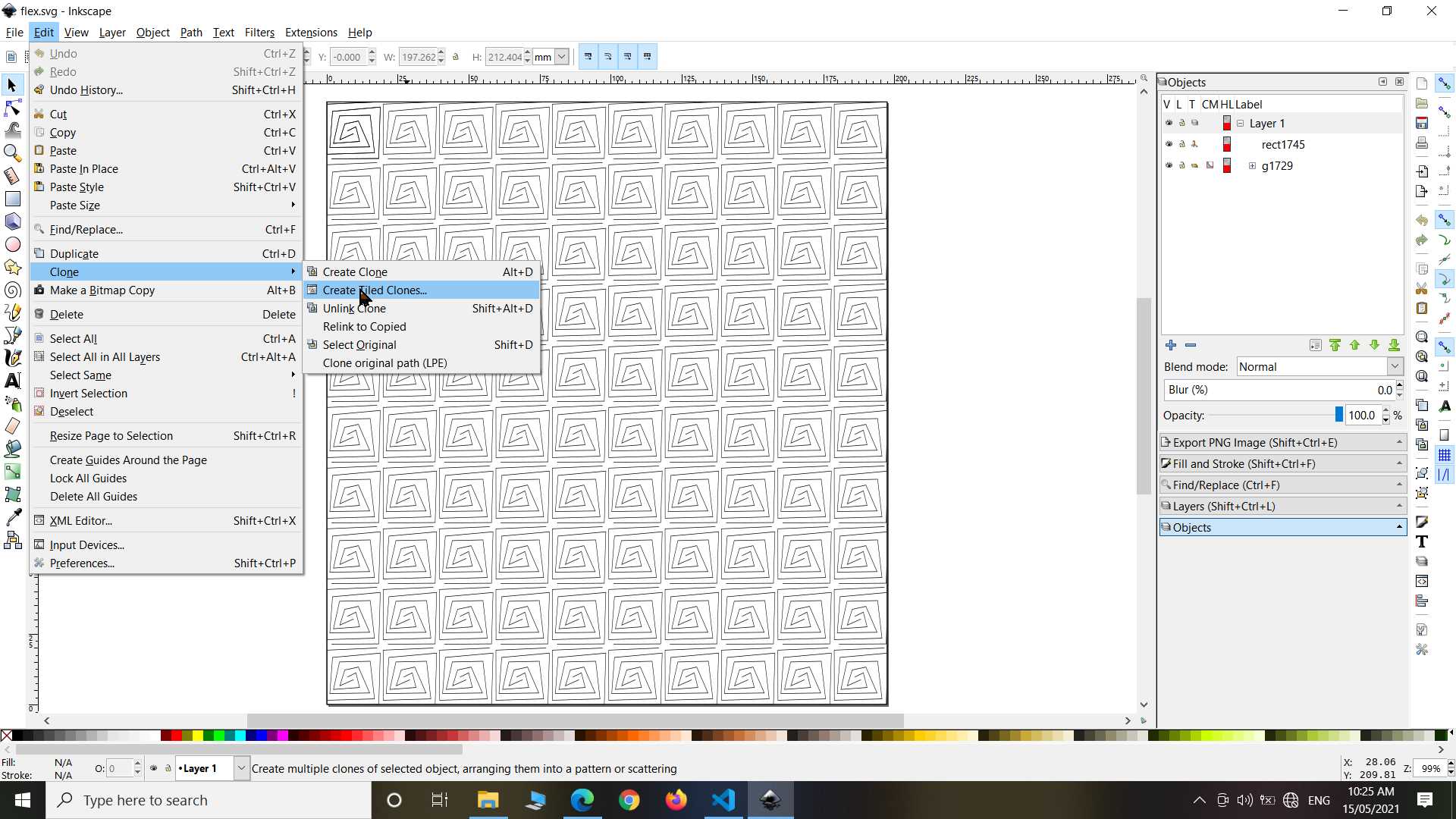
So this is just a experiment to proof concept but you can add it in your design to make it innovative.
.jpg)
.jpg)
So It came out well just one issue is that my patter was wrong it not became too much flexible but okay it it all depend on patterns you make and another was that some trace are very thin and got broken while rough handling.
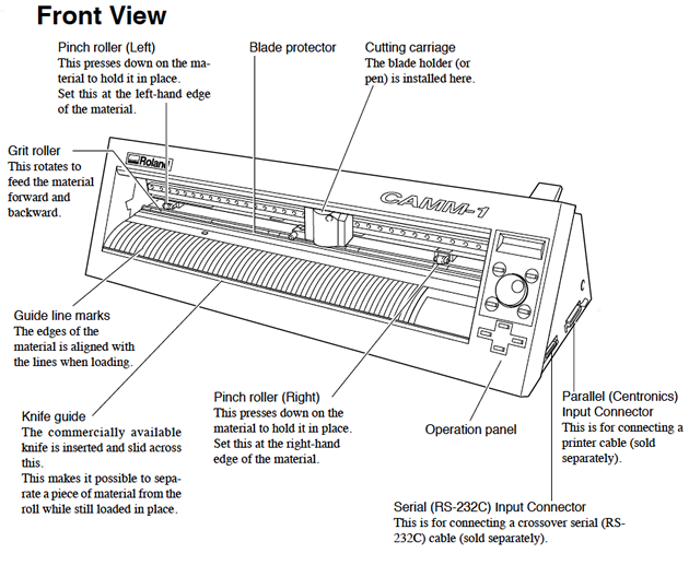
VinylCutter:
.jpg)
Vinyl polymers are a group of polymers derived from vinyl monomers of the type CH2=CHR. wikipedia
Vinyl paper are sheet made of vinyl polymer kind of plastic. It is used in making stickers and masking. since it not only use of it but till now I know only this much.
VinylCutter is cnc 2d cutting machine used to cut design on vinyl paper...
This machine use blade to cut vinyl paper. Blade is sharp so handle with care. Since it use blade any possible material can be experiment like normal paper, copper tape to make flexible PCB
.jpg)
.jpg)
Supported software
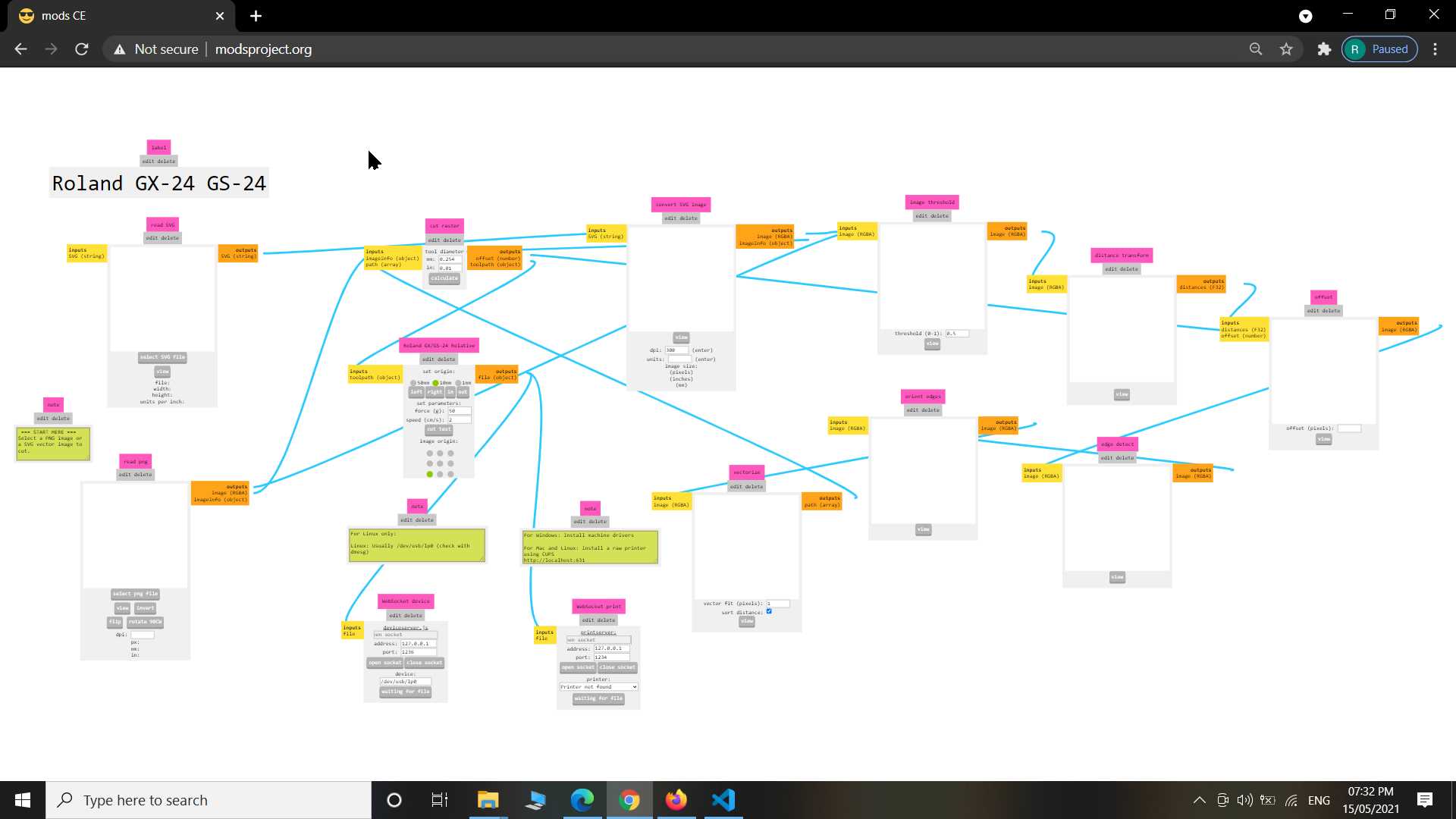
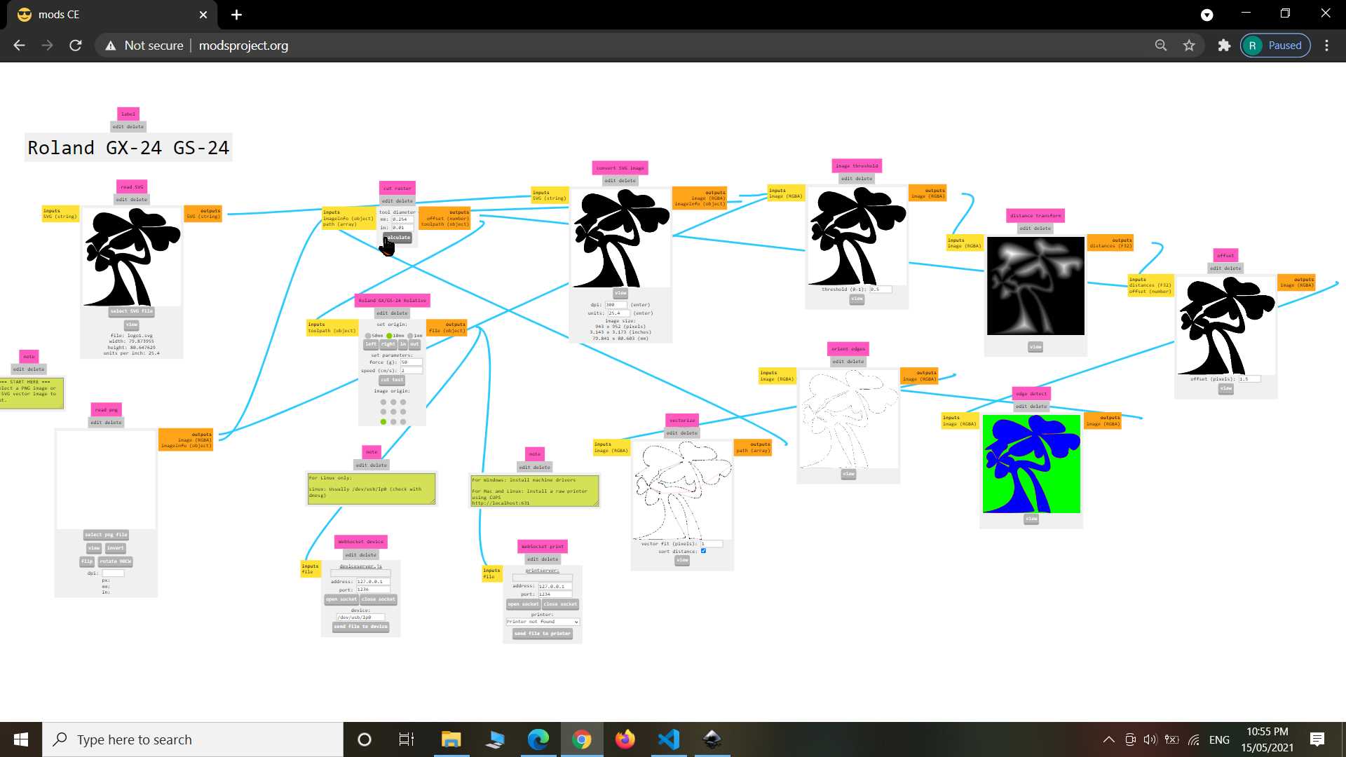
So you can operate this vinylcutter using modsproject. It support svg and png files...
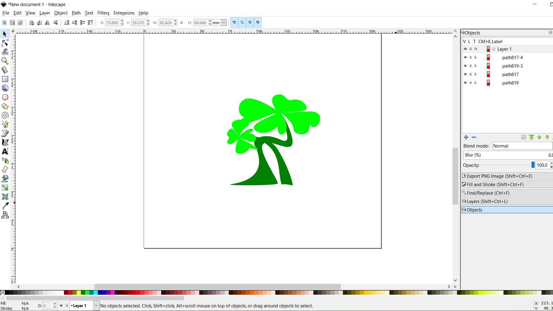
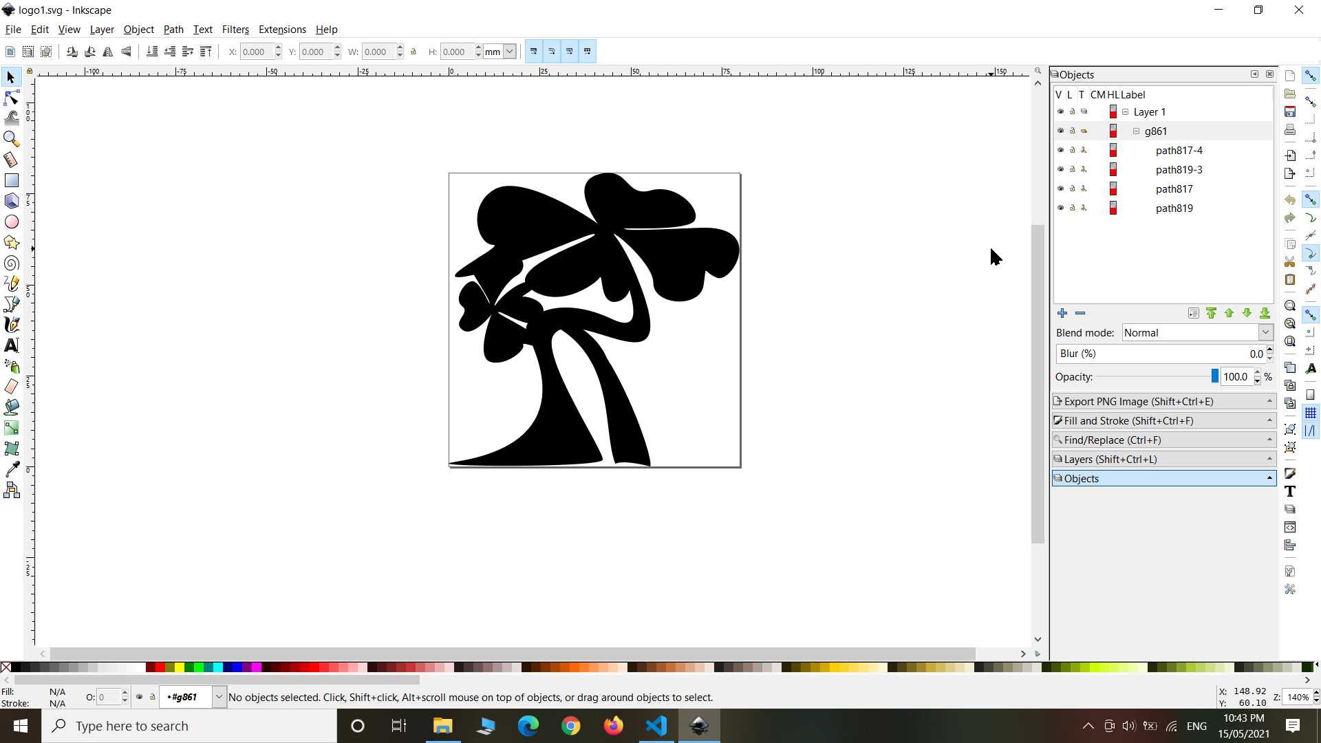
I made plant logo using Inkscape. First I made colorful design but to make it colorful we need multi color Vinyl paper and that I dont wanted to do now. So I combined all shape and gave them one color black. Thing to note that whatever color you give in design it is not important since vinylcutter is a cutter not a printer so all depend on which color vinyl paper you using
To learn more how to use this vinylcutter machine visit
last I opened my svg file in modsproject to operate vinylcutter
cutting pressure is needed to adjust carefully so cut come out good. My cutting came out nicely
.jpg)
.jpg)
So my design was simple so it got out easily. Vinyl paper is use for sticker so it have glue on it. After removing off design I stick it on my box and that how it look
.jpg)
.jpg)
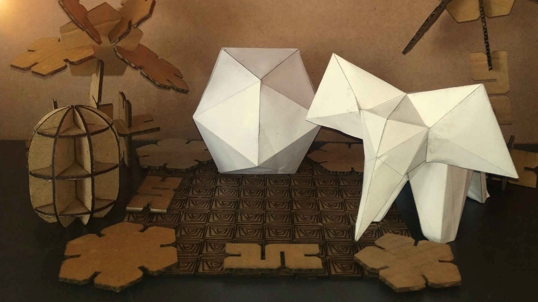
Paper models
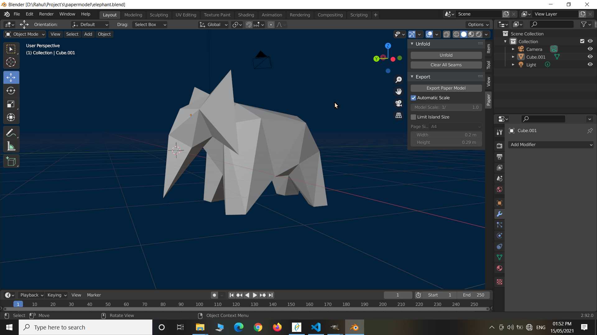
In CAD designing week I have explored addon in blender called papercut model which allow to convert polygon model to folding paper cut model. Here I move fast and skip details to cover what I have done it.
So I designed low poly elephant in blender and using paper cut addon I made whole 3D model Unfold on 2D pages.
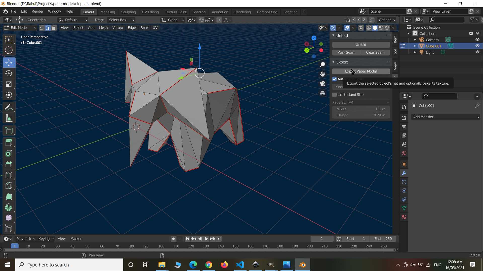
Exported it in pdf file and made ready to print.

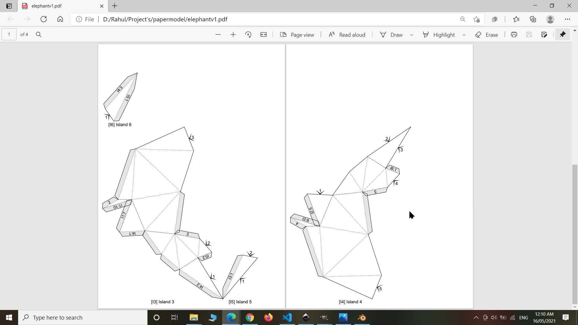
So I printed it using normal desktop printer on A4 sheet and then cut it out using scissor. yes it is not machine cut but I think if needed vinyl cutter can be use for it even lasercutter can do this job but then you need specify which line needed to cut and which line is for folding.
.jpg)
.jpg)
It took almost 75 percent of one whole day to glue it and make it look like this...
.jpg)
.jpg)
.jpg)
I designed IcoSphere in my cad designing week and made it on this week
Completed!
Learning outcomes:
So I had done many experiment with lasercutter all got Completed well except flex one because I forgot to put design in alternative pattern It went wrong and it was failed experiment but will try again. I have used VinylCutter less because I have not much to do with it. I enjoyed paper fold modeling and liked and seeing way forward to make more paper toys. With many other dreams I have little wish to be toy marker and I am seeing this tools can be very helpful. I enjoy making with hand and with technology and have no political thought on both of them.