Computer Controlled Machining
Making something Big...
Intro.
This week I have to build something big as for human size thing For that we using Big CNC milling machine (ShopBot). It can be Making a Chair, table etc for our own use using plywood.
Week Task:
Group assignment:do your lab's safety training
test runout, alignment, speeds, feeds, materials, and toolpaths for your machine
Individual assignment:
make (design+mill+assemble) something big (~meter-scale)
Group assignment: summary
So in Our lab we dont have big cnc milling machines so we all have to travel outside to other lab to complete our this assignment.
But since In this Covid pademic so most of our work is on hold but later We managed to complete it
to know more about group assignment
ShopBot PRSalpha
.jpg)
.jpg)
.jpg)
Individual assignment:
Before machining I have to prepare my design. I have not done this work before so this will going to be interesting with more learning experience
Designing
So I was thinking about to make something decorative and piece of art for our fablabs. I have animal picture in my mind like bear and elephant so I gave time to myself to get in touch with my thought.
So Quickly I made a rough Design in blender to see how it will look.
.jpg)
.jpg)
so I fixed elephant shape shelf but later I Experiments with different possiblity in my design. As you see below image In CAD designing I trying to modified design to something new.
.jpg)
.jpg)
.jpg)
After few try and I landed on final design. Here below you see design that evolved from old one. Okay! one thing forgot to say I am using autodesk inventor for cad designing.
.jpg)
.jpg)
.jpg)
so next as you see in three below image what mistake I have done is I have not made every parts separately and soon I have found that, that was not good practice but I managed to work with this way.
.jpg)
.jpg)
.jpg)
.jpg)
.jpg)
.jpg)
Here I done with shelf design and after assembly that how it look. Beautiful!
But work is not completed yet I created notches to make shelf pressfit but ofcourse in practical I need to put glue so it remain as it is for long time. So idea behind putting notches is to make easy to align all parts and to deal with dogbone concept
.jpg)
.jpg)
.jpg)
so making of multiple notches using conventional draw and extrude cut method is a pain
I thought why not to make notches to one part and using boolean operation make complementary notches on other parts and in this way I may save time and effort
so using copy object tool in assembly I copied one part to another part file and last using combine tool in part mode to make boolean operation
.jpg)
.jpg)
Even after all that effort still remain to put a dogbones on each inner sharp corners. It is a headache. but I tried with some shortcut I know as you see in below images and none work well
.jpg)
.jpg)
.jpg)
.jpg)
Until here I finally decided to give up doing it manually and search over internet for better option. who keep making dogbone one by one on each corner ofcourse there must be solution already, that was my believe. So I pause here
Next Before moving further with toolpath I export 2d draft of parts into .dxf and brought everthing together accordingly into two pdf files since I going to two different size plywoods 12mm and 8mm for my design
.jpg)
.jpg)
.jpg)
Since building actual size shelf will take some more time due to travelling limitation occur by corona. But what I have done I shrink my design, removed notches because it conflicting with material thickness and using with laser cutter I made it.
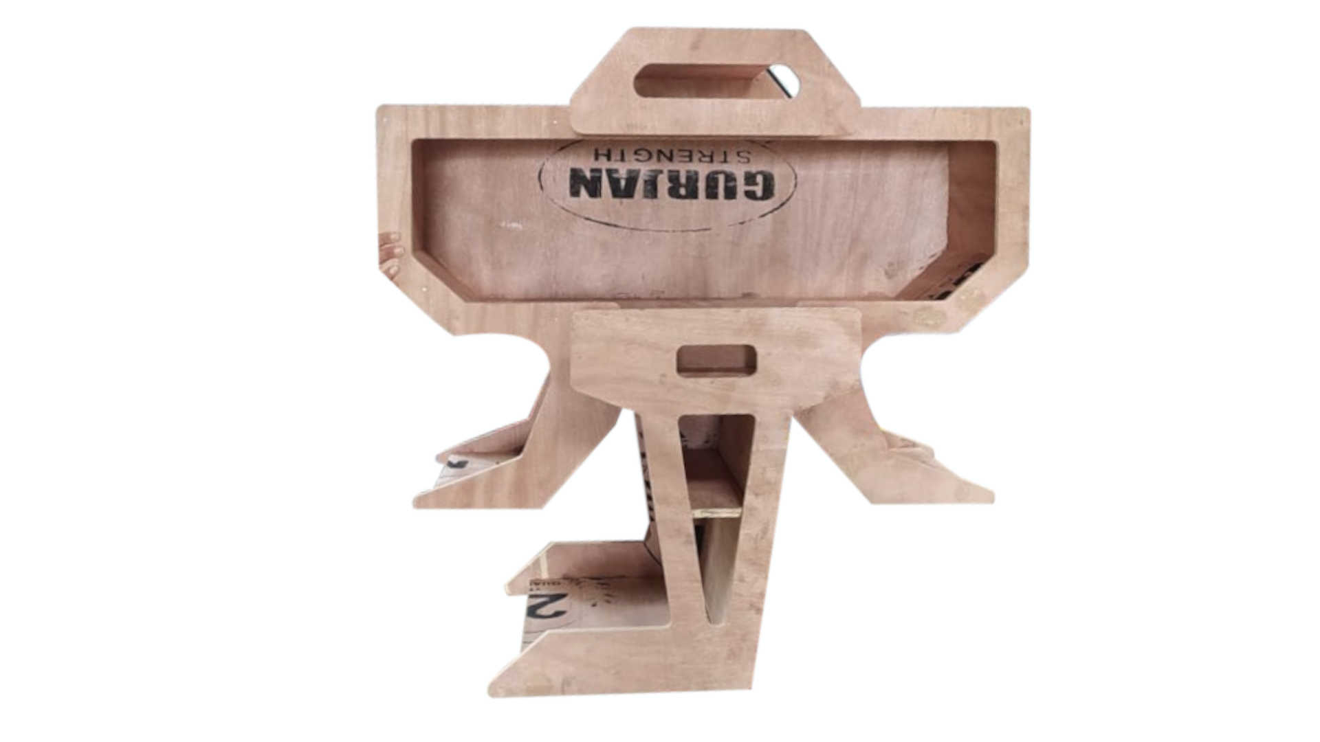
Here my small model of shelf
.jpg)
.jpg)
But this will not complete my assignment because it week is for making something big and also toolpath and cutting using cnc milling is very different from laser cut. This because milling machine can't cut inner corner easily therefore it needed to add dog bone cut on each inner corner
So to proof myself this thing I generated toolpath on small part of design in fusion 360 and simulated it
.jpg)
.jpg)
.jpg)
.jpg)
.jpg)
.jpg)
.jpg)
.jpg)
.jpg)
Trying with more parts
.jpg)
.jpg)
.jpg)
This part was just to play with it and to explore toolpath generating in fusion 360. But I am not going to use this toolpath for final cutting because we are going to use shopbot and it support software called partwork that we dont have here and It is not available for download it come with machine itself. So I paused until I find alternative
Now let continue with doggie bone issue. After long search I found a way to apply doggie bone pattern to all inner corner automatically using fusion 360 scripts. So I import my inventor model in fusion and after applying I brought model back in inventor to prepare 2d draft for cutting
.jpg)
.jpg)
.jpg)
After some search I found alternative of partwork software known as vcarve to make toolpath.
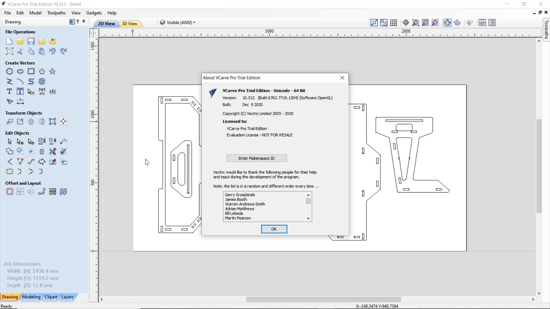
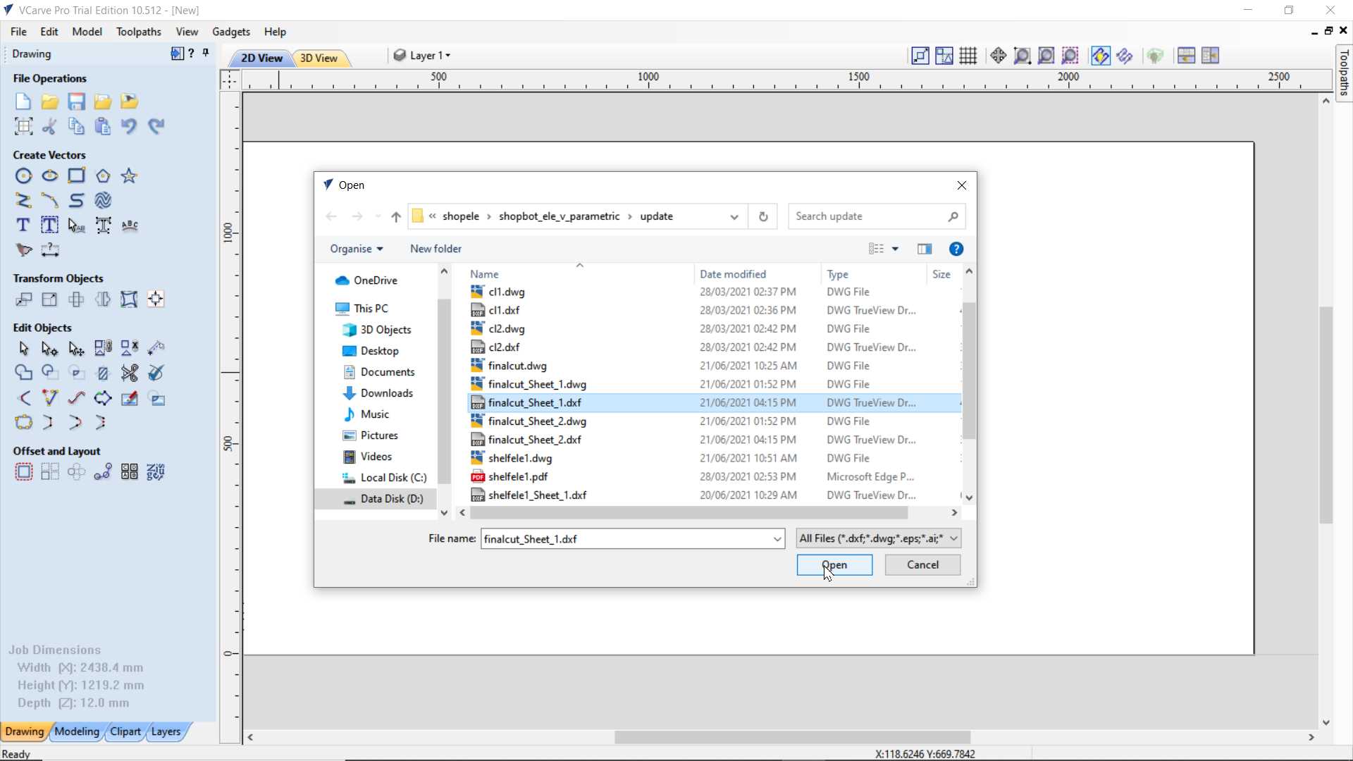
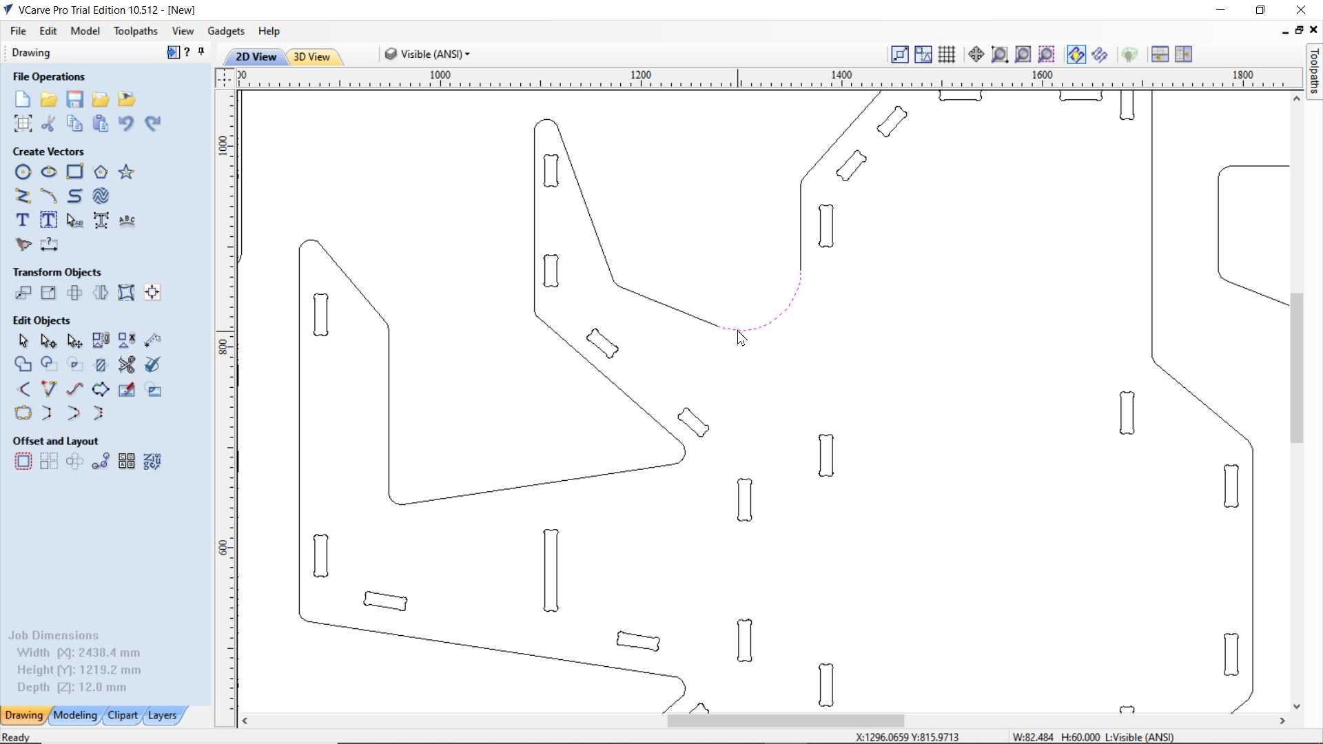
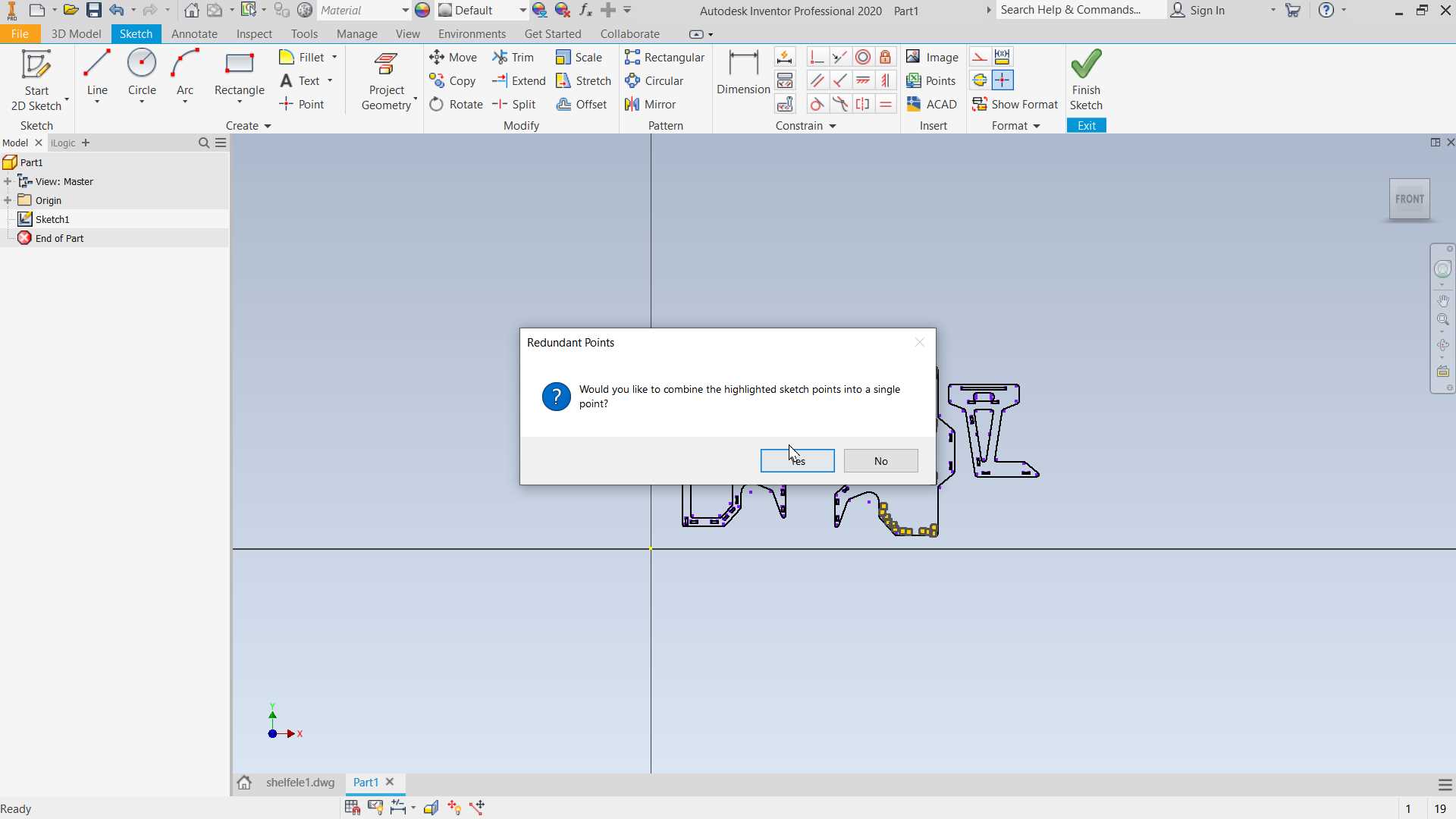
I just started with it I found new issue of in my design it have open loops
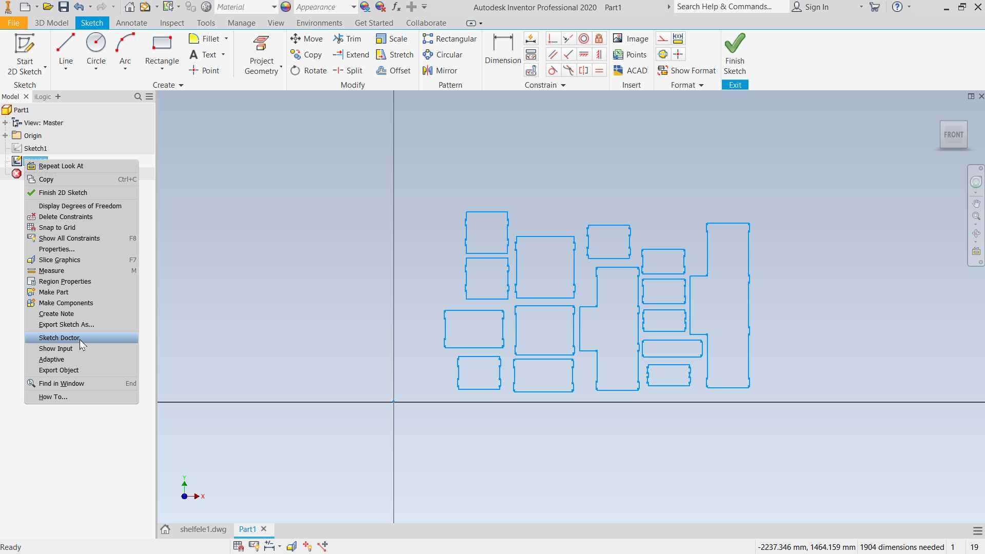
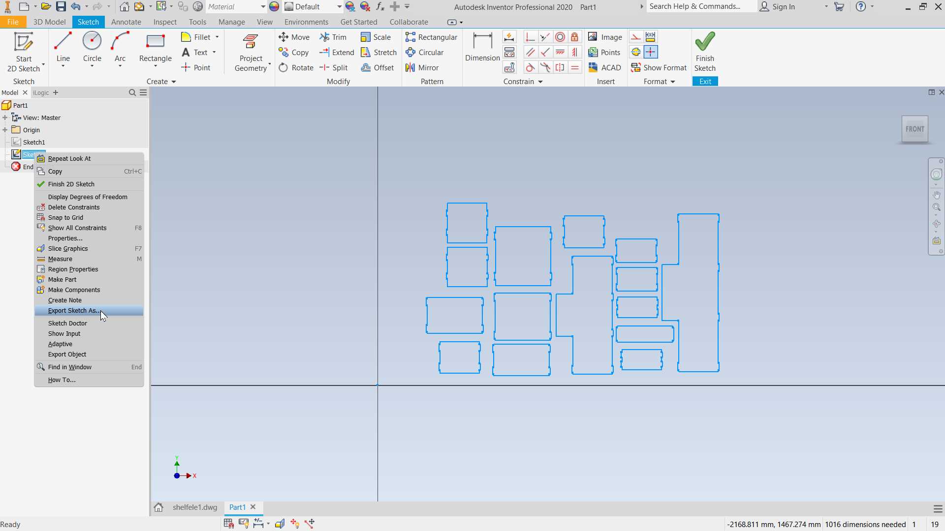
To solve this issue I made new .ipt file and imported my 2d design in a sketch and using sketch doctor I closed loop and exported it back to new dxf
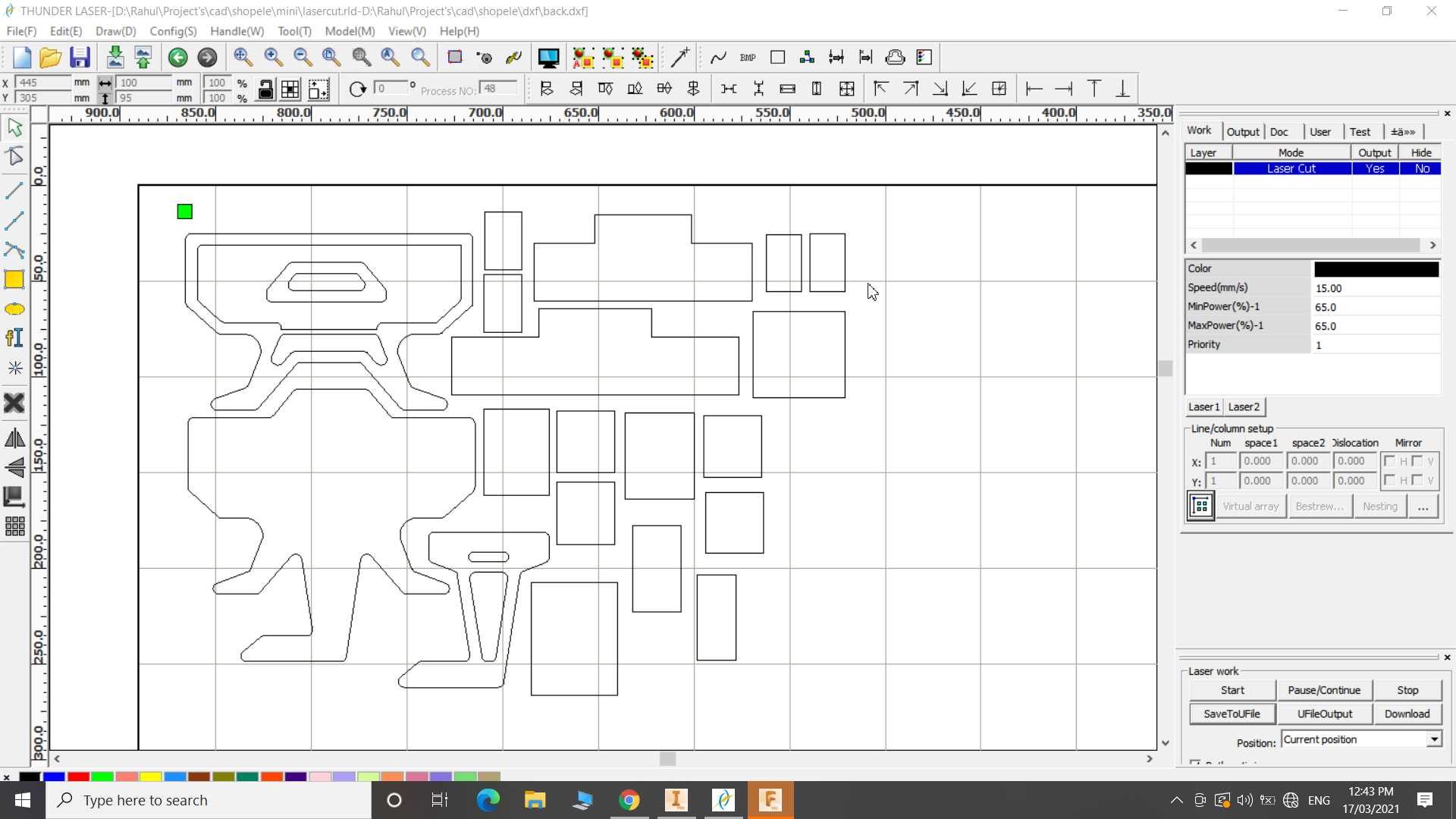
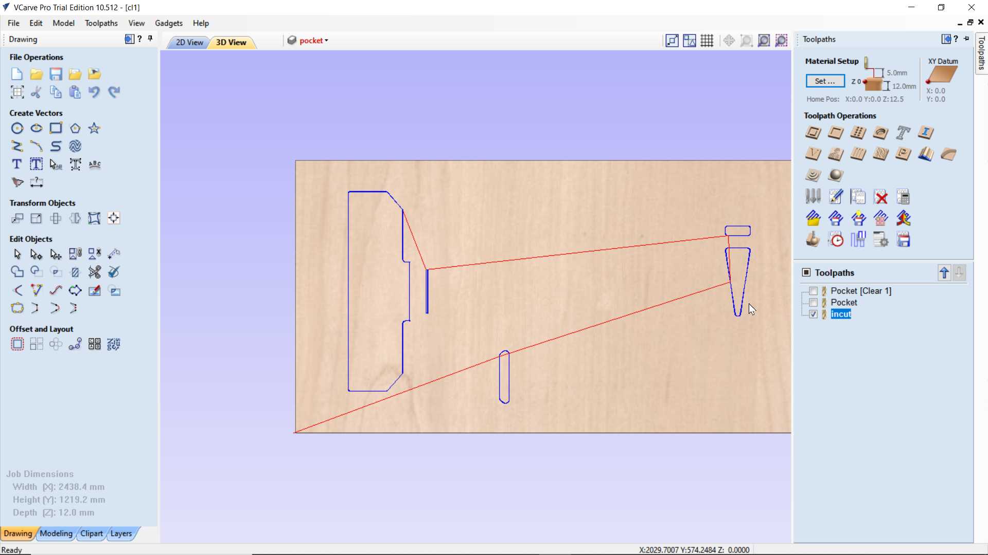
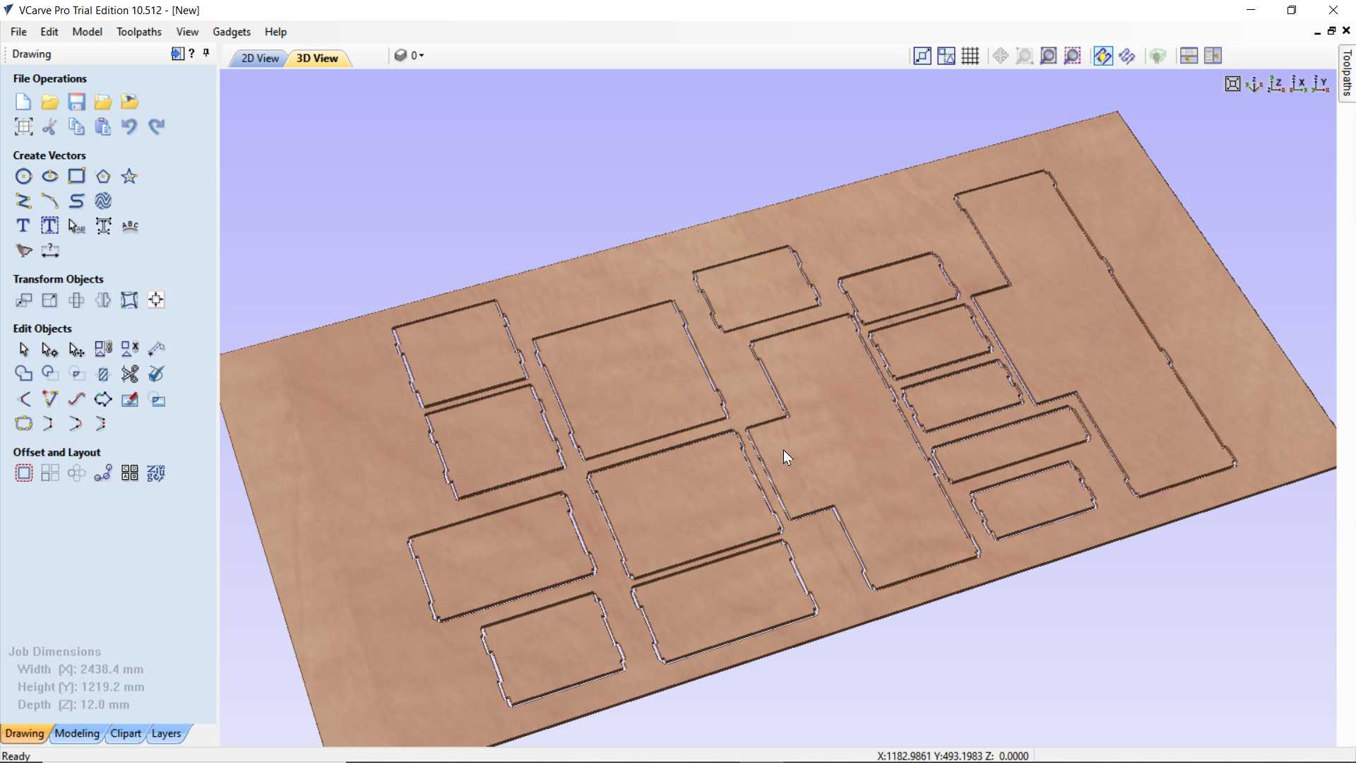
Generating toolpath using vcarve
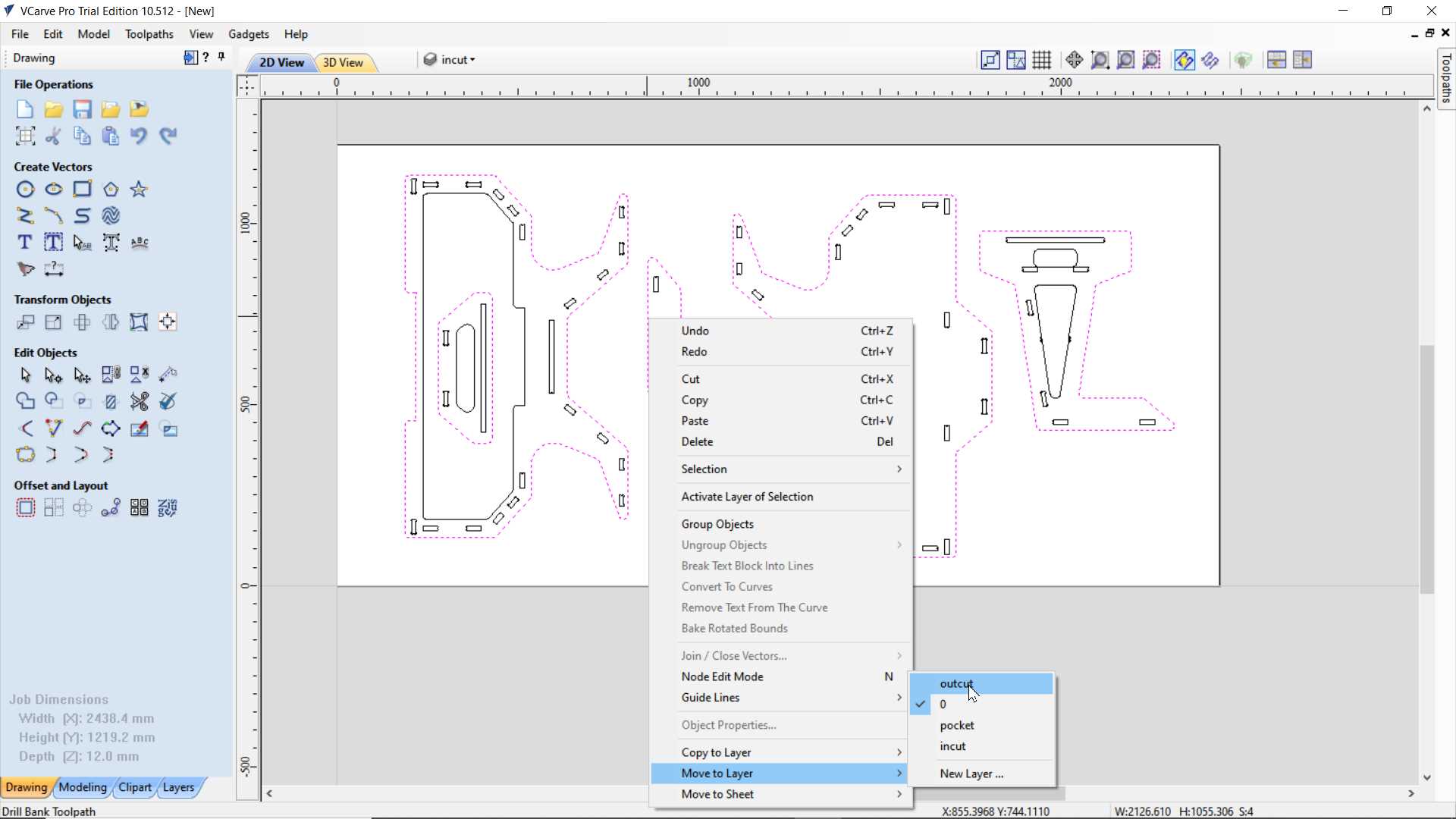
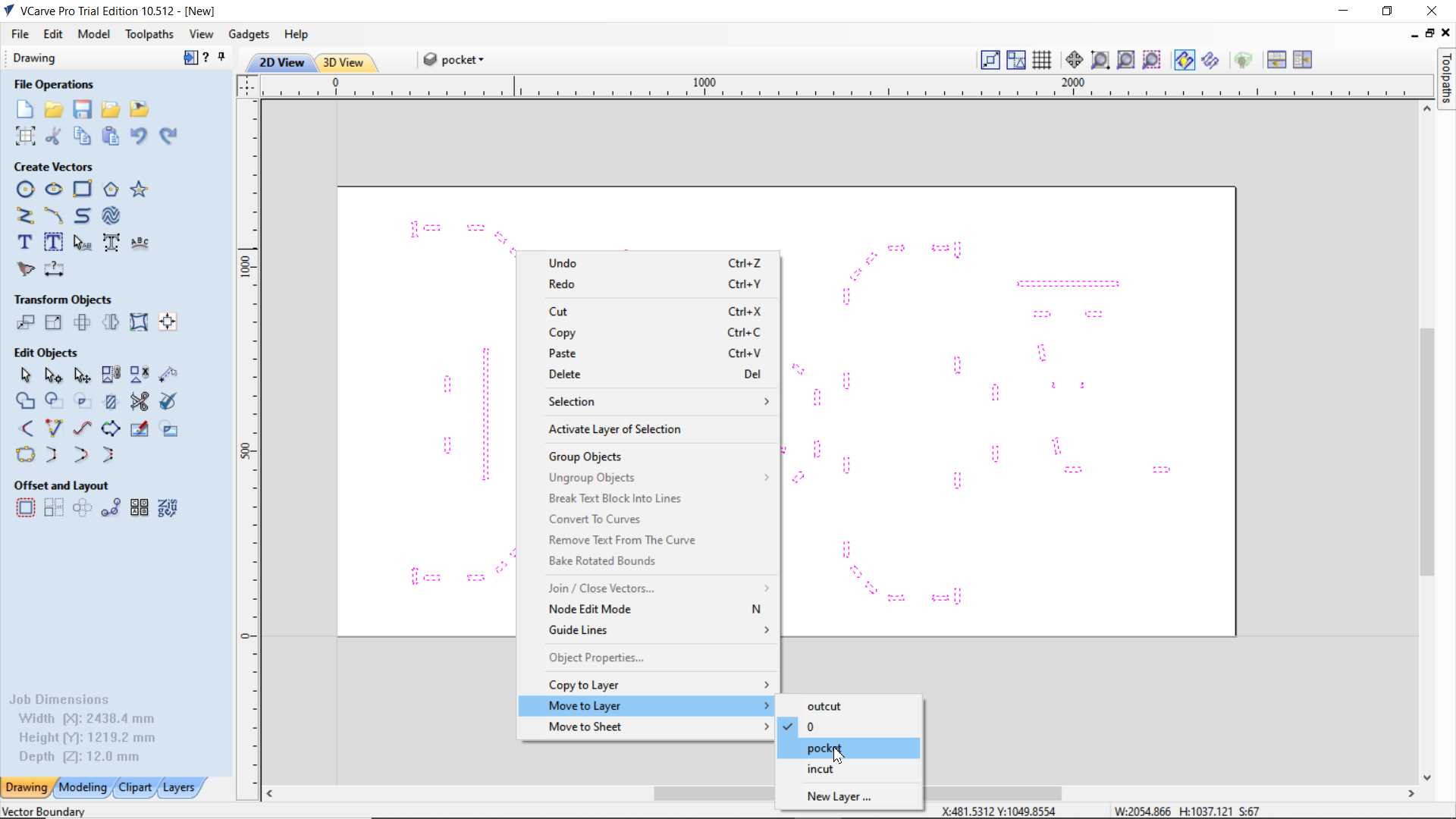
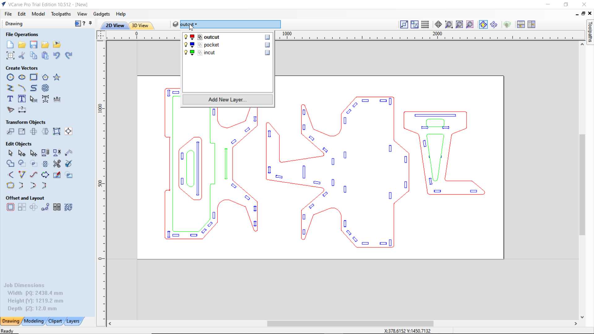
So finally I making toolpath. My design have little complicate cuts so I separated my design accordingly to types of cut I will apply. Name layers into three group pocket, incut and outcut. so In pocket I added all notches. Then in incut I added inner cutting loop and in outcut I added final outer edge cut.
setting up material thickness and other setting
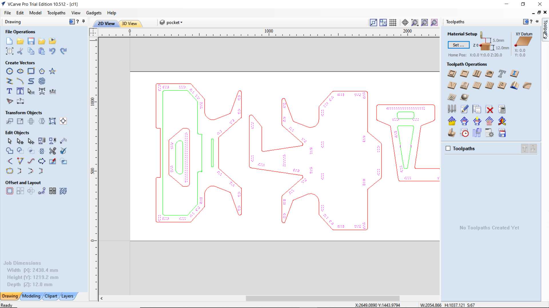
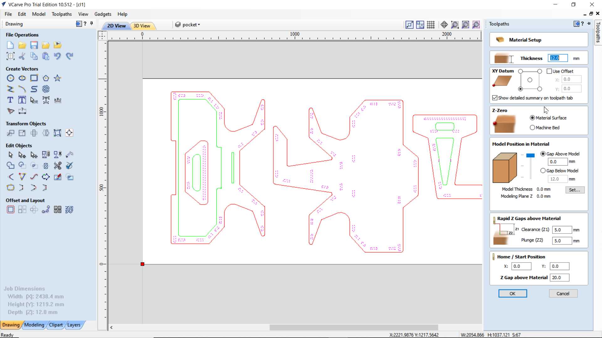
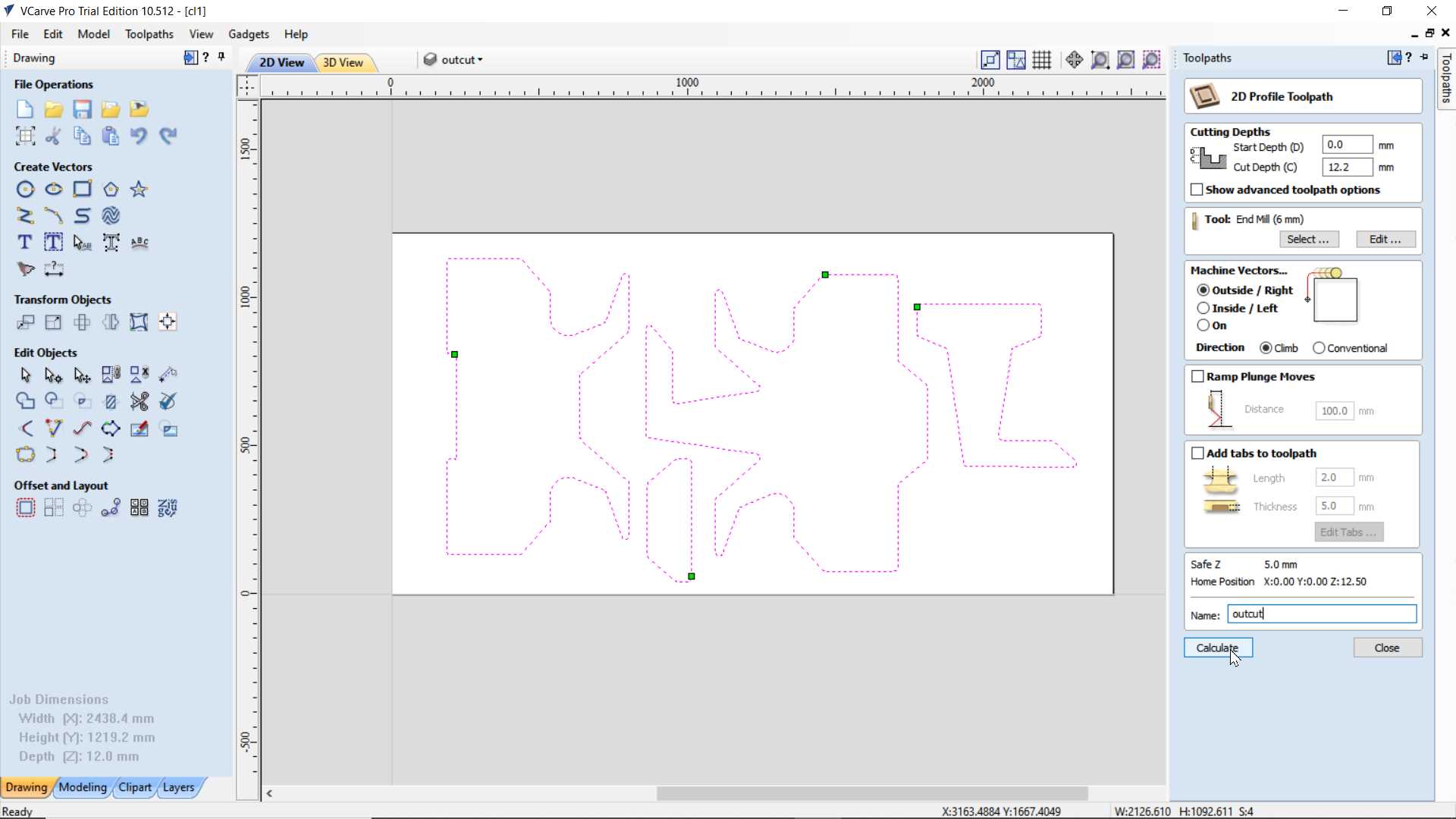
Applying pocket operation on pocket layer and profile operation on incut and outcut layer respectively
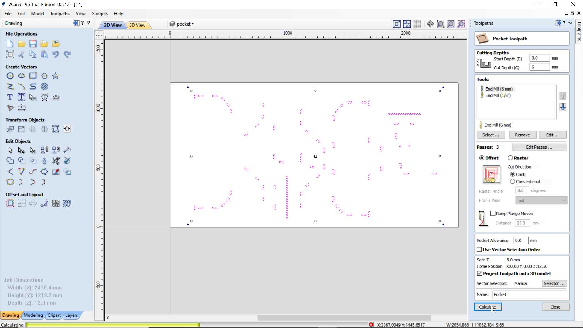
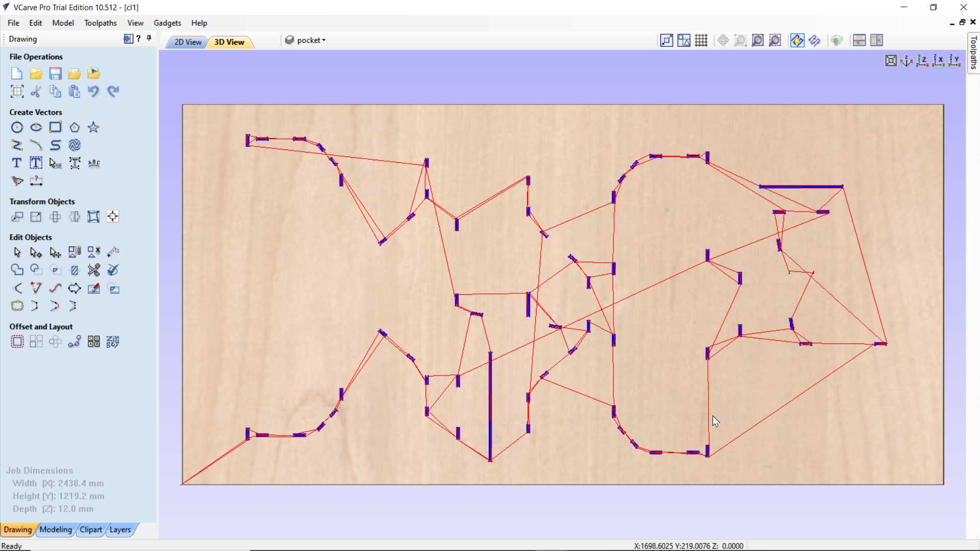
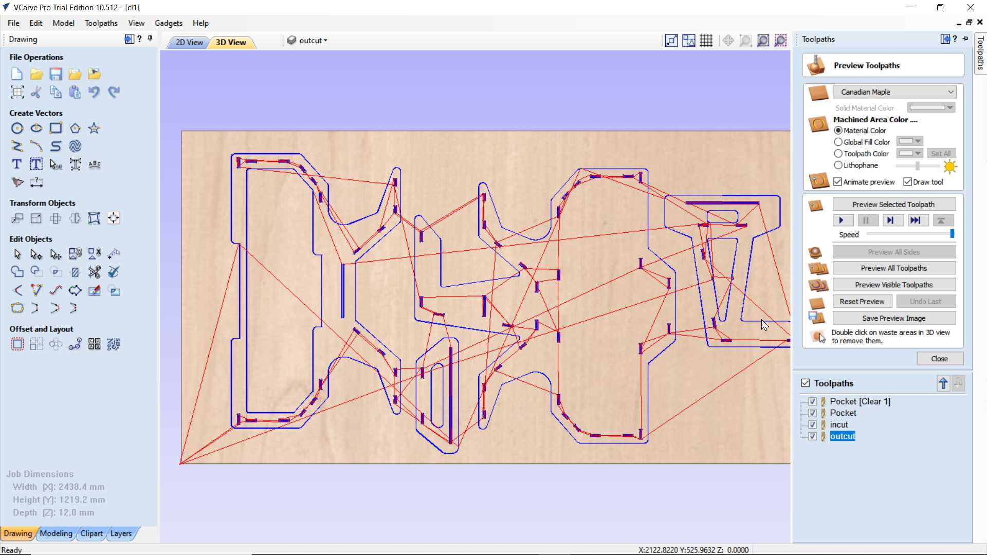
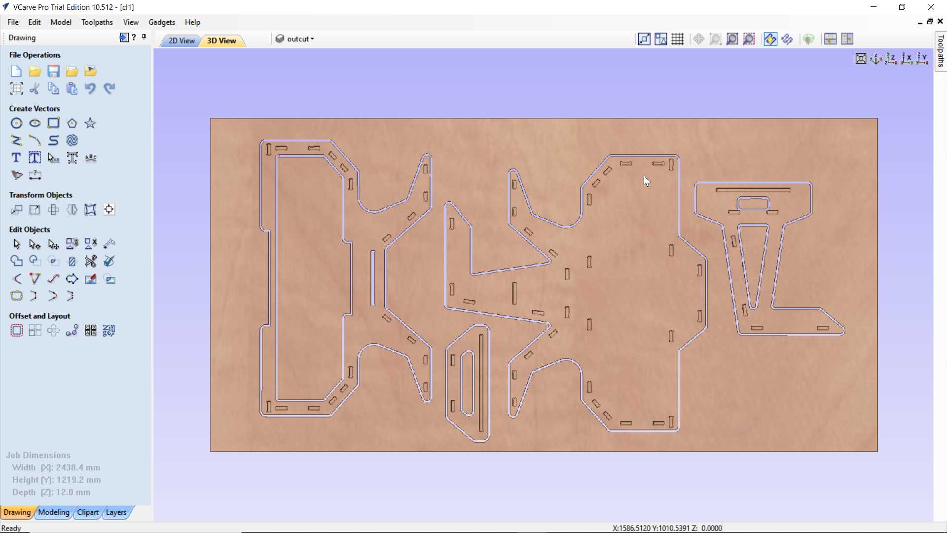
Preview of final cut. I have two file and for both I am using 12mm sheet because 8mm was giving issue in doggie bone with 6mm bit
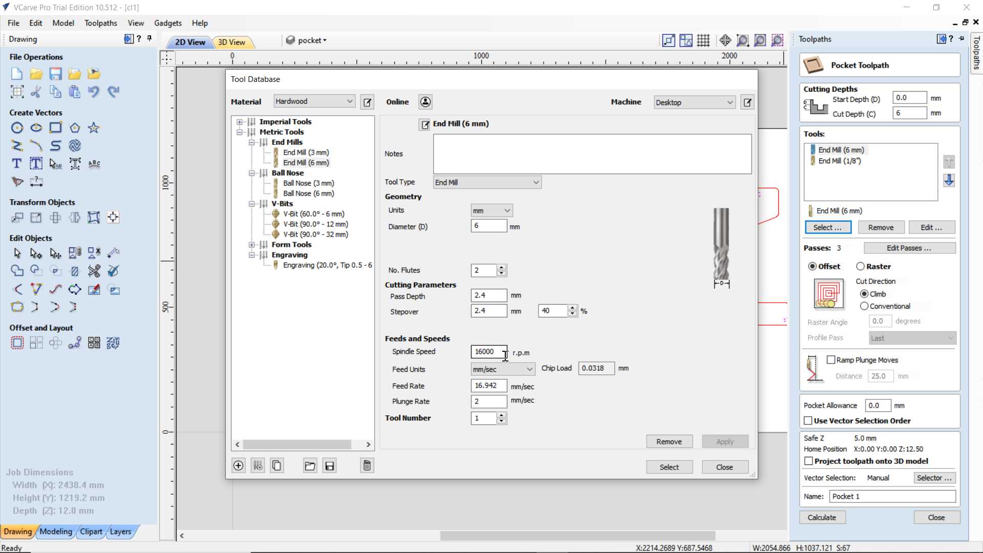
Important Paraments:
Spindle Speed is a rotational speed of the cutting bit measure in R.P.M and can be adjusted
Feed Rate is a speed of bit move on x and y direction while cutting materials.
Plunge rate is a speed of bit moving on z direction while cutting materials
Stepover is defined as the the space between passes of a tool during an operation.
Number of flutes here is 2 and cutter diameter is diameter of bit
Chip load is a measurement of the thickness of material removed by each cutting edge during a cut
The formula for calculating the Chip Load is:
Chip Load = Feed Rate in inches per minute / (RPM x # flutes of the bit)
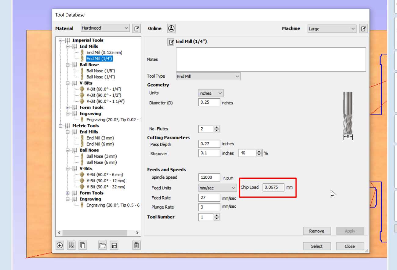
So Here are suggested setting and it give Chip Load is 0.0675 mm i.e 0.0026 inch
On internet search I found this:
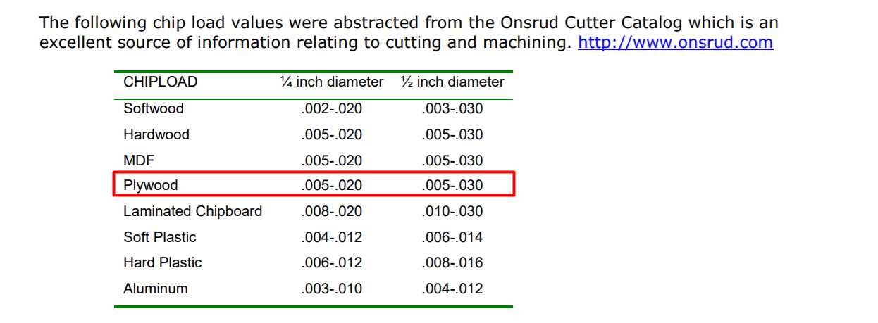
There is lot different in my value and value given on chart I have not done a proper test due to limited access so can't say which one is best
A spinning bit generates friction and heat as it moves through the material. Heat is damaging to the carbon bits generally used in CNC machining, so they will become dull and/or break if allowed to get too hot.
When the waste generated by the machining process resembles dust (the smaller the chip load), the more heat stays on he bit.
With a larger chip load, more of the heat is transferred to the flying chips, so the bit stays cooler.
But there can be too much of a good thing. A chip load that is too large puts more stress on the cutter, causing a rough cut, bit deflection, and/or bit breakage.
Now its time to Cut
So after few week later I got to cut my design finally on ShopBot
Vcarve files didn't worked here with partwork it old version file
But I managed to make path again in partwork almost same like in vcarve
After saving a path that have be generated It need to upload in software that instructs shopbot machine.
.jpg)
.jpg)
.jpg)
So my plywood actually was not flat. it doesn't look bend but it is not perfectly flat so when I applied pocket operation on some pocket bit went through plywood
.jpg)
.jpg)
Here after completing pocket jobs
.jpg)
.jpg)
.jpg)
Next inner Cut. This went smooth but it need care because I have not added taps that prevent part to stay on part while cutting process complete so each time for each part I have to pause process and manually take out cut part from plywood
.jpg)
.jpg)
Same process for outercut
.jpg)
.jpg)
Here all cutted parts
.jpg)
.jpg)
.jpg)
So I tested if it pressfit properly.
Since pressfit will not give that strength I used glue and nail. In that I took help of extra hands
.jpg)
.jpg)
.jpg)
Here how completed shelf look like
.jpg)
.jpg)
So I fill up all unwanted holes that form while pocket operation with a wood dust and glue
tolerance/margin
I have designed whole structure with exact cut-to-cut size and paraments since here there was no need of calculating kerf I thought so I design everthing with exact size I wanted. Since due to limited access we in group or Individual have not explored pre-testing to calculated tolerance with shopbot. I directly jumped on final cut. Since after cutting I have done some finishing manually like sanding off surface even more to make parts attach properly. Since many thing influence it like plywood that I have used is not with even thickness. But overall it not took my too much effort and with little hammering as you see in video I placed everthing in it place. So on observing and measuring output rough idea is that we can considered 0.5 to 1 mm +/- cutting tolerance in design but not sure of it needed more exercise with this machine.
Learning outcomes:
So I made shelf that shape like elephant but here people see it like ganesha (Hindu god with elephant head) thats okay I am happy that people can related with it. Since due to covid situation I got delay to cut it on time but later when I got chance I Finished it and updated hero shot on top of this page. I somehow managed designing this shape I got little fear that it will work or not but I told myself it going to worth it. I have not polished and painted it yet but hope I able to do that in future but as a part of assignments is done for now.