

WildCard Week:
In this Fifteenth week of Fab Academy, we had room to explore from many options like creating machines, welding, molding and casting, robotics, inflattables, electronics, embedded programming, food technology, materials, biotech, textiles, composites etc.
Objective:
Design and produce something with a digital fabrication process (incorporating computer-aided design and manufacturing) not covered in another assignment, documenting the requirements that your assignment meets, and including everything necessary to reproduce it. Possibilities include but are not limited to wildcard week examples mentioned above.
Learning Outcomes:
Checklist:
Opening Quotes:
- Confusion is a word we have invented for an order which is not understood. "Henry Miller"
- God turns you from one feeling to another and teaches by means of opposites so that you will have two wings to fly, not one. "Rumi"
- "It’s pretty confusing."
Good. Be confused. Confusion is where inspiration comes from. "Robyn Mundell"
Embroidery Work on CNC Sewing Machine:
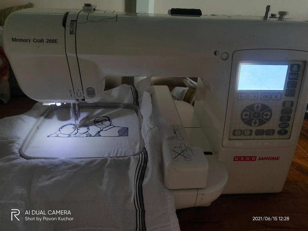
USHA Janome Link is other CNC machine in our Sewing Lab. Embroidery and other sewing designs could be also printed on this machine. I decided to use this machine for this WildCard week.
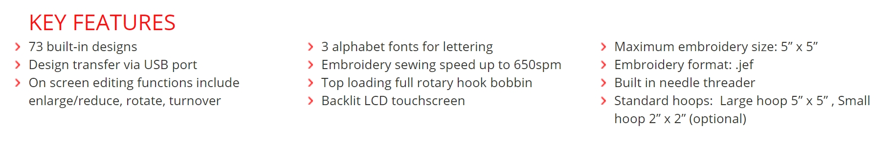
Features of the USHA Janome Memory Craft 200E CNC Sewing Machine:
As I have been away from my Family since 5 months and I was feeling very Nostalgic, so I thought of designing the Portrait of family and printing it on the Handkerchief.
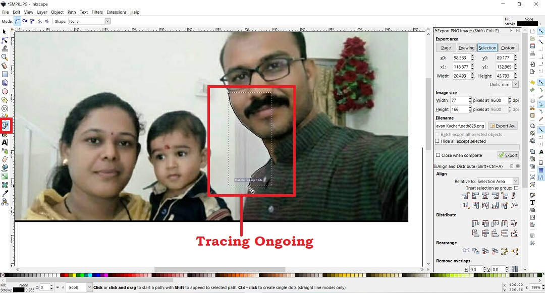
I took one of the Images from the Album and opened it in InkScape. Then I used the "Draw Bezier Curves and Straight Lines" Option to trace the Outline of the Image.
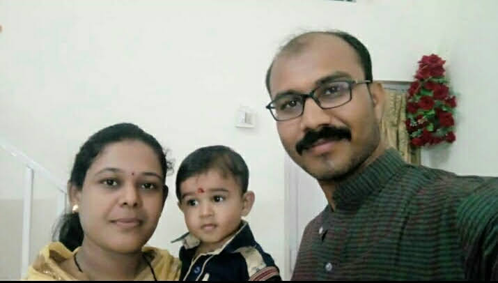
Original Image used for Tracing
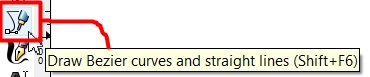
Tool used in Inkscape for Tracing the Outline of the Image
Then, I saved the resultant Trace as .svg file. I then added Text to it as "My Family" and "Sarve Bhavantu Sukhinah" - a Sanskrit hymn which means "Let All be Happy" to it. Then I exported the File as .jpg as this .jpg format is required for the Embroidery machine.
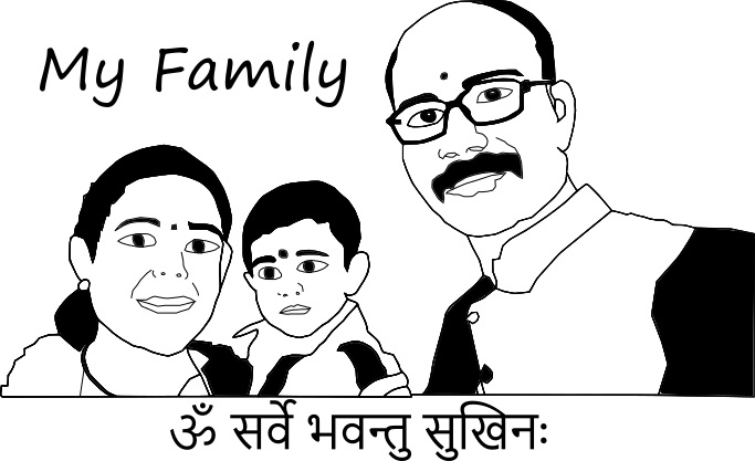
.jpeg File of the Image for Embroidery
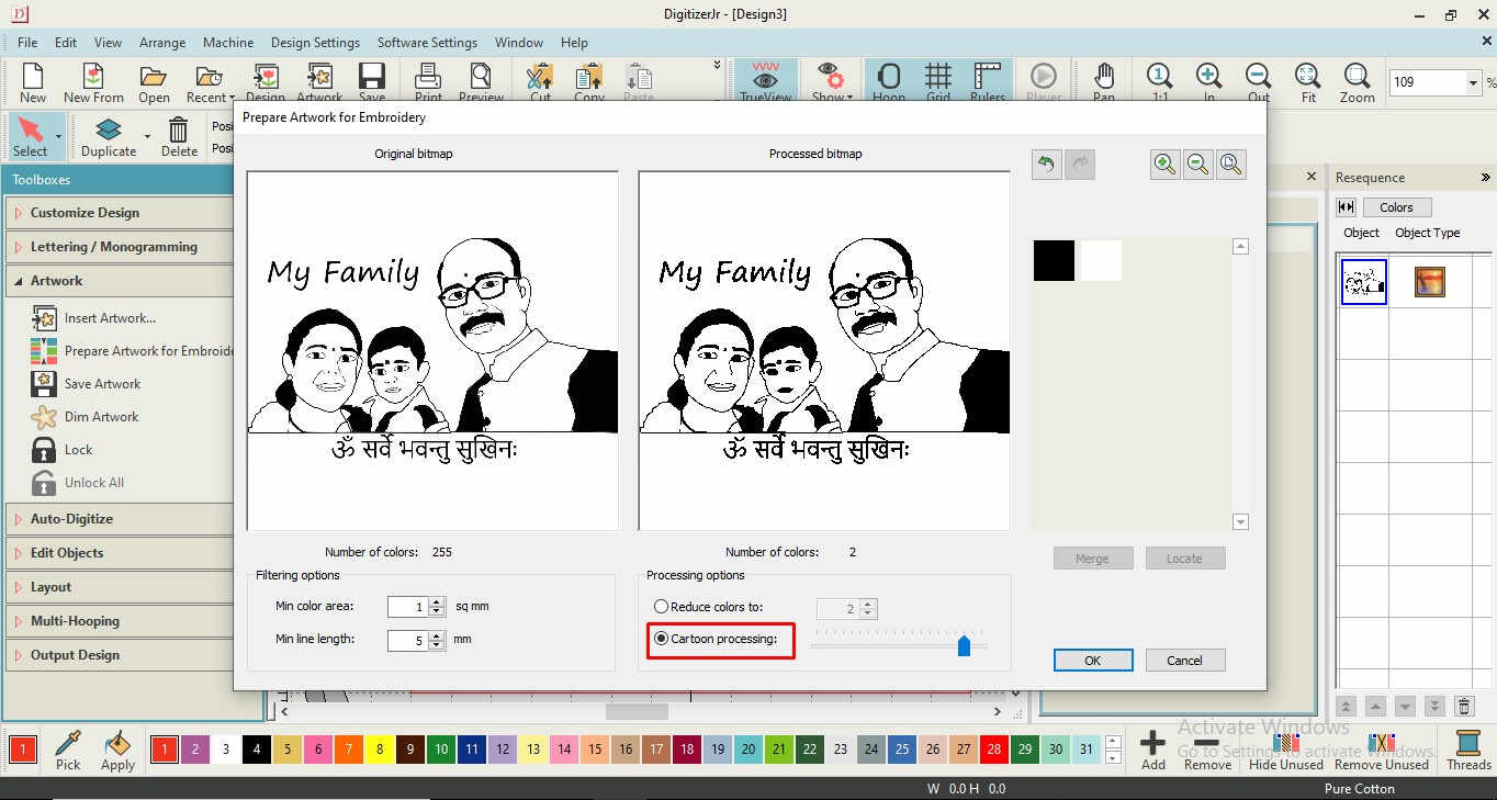
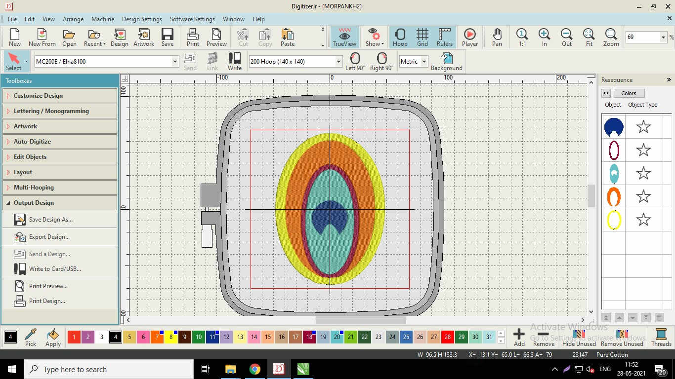
Digitizer Jr V5 software for Embroidery machine USHA Janome
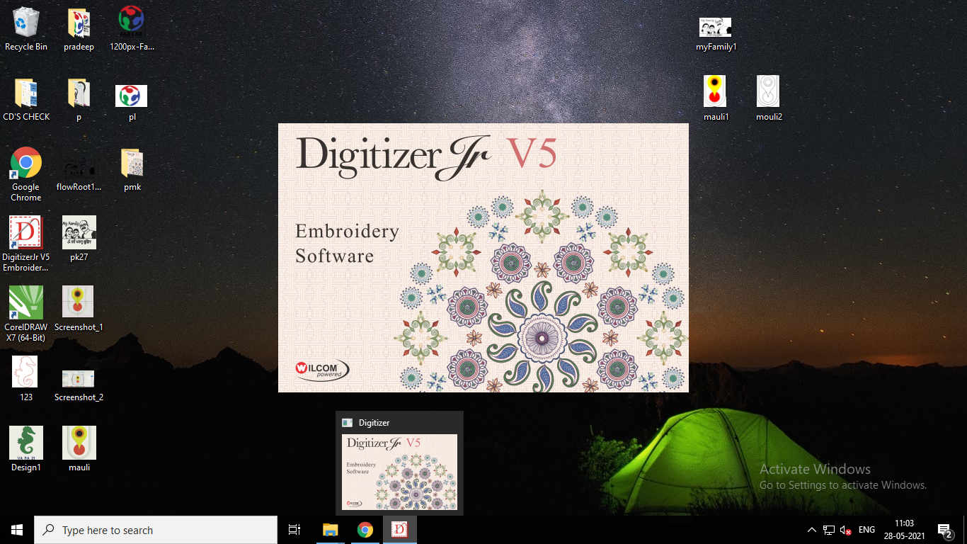
I opened the Software for creation of Toolpath
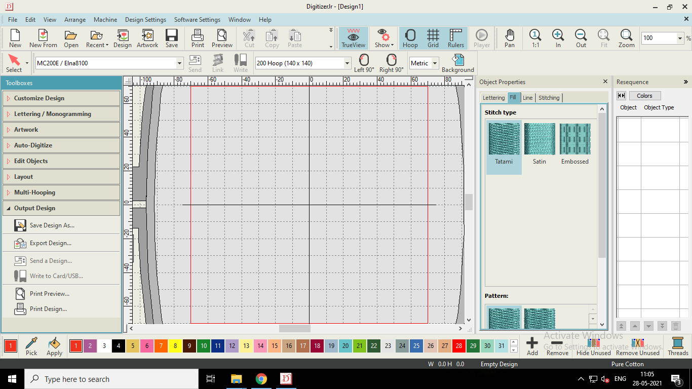
Window of the Software
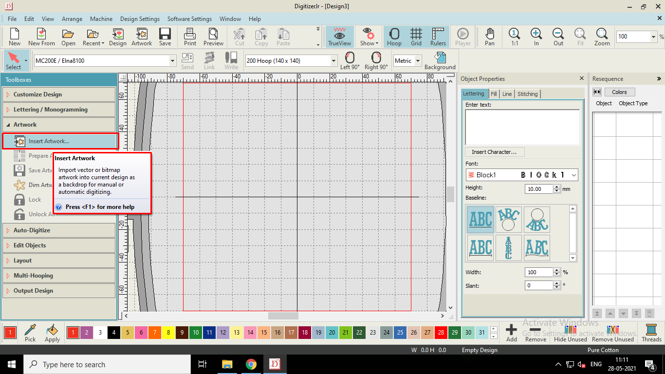
Insert Artwork for Processing
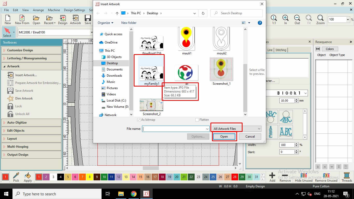
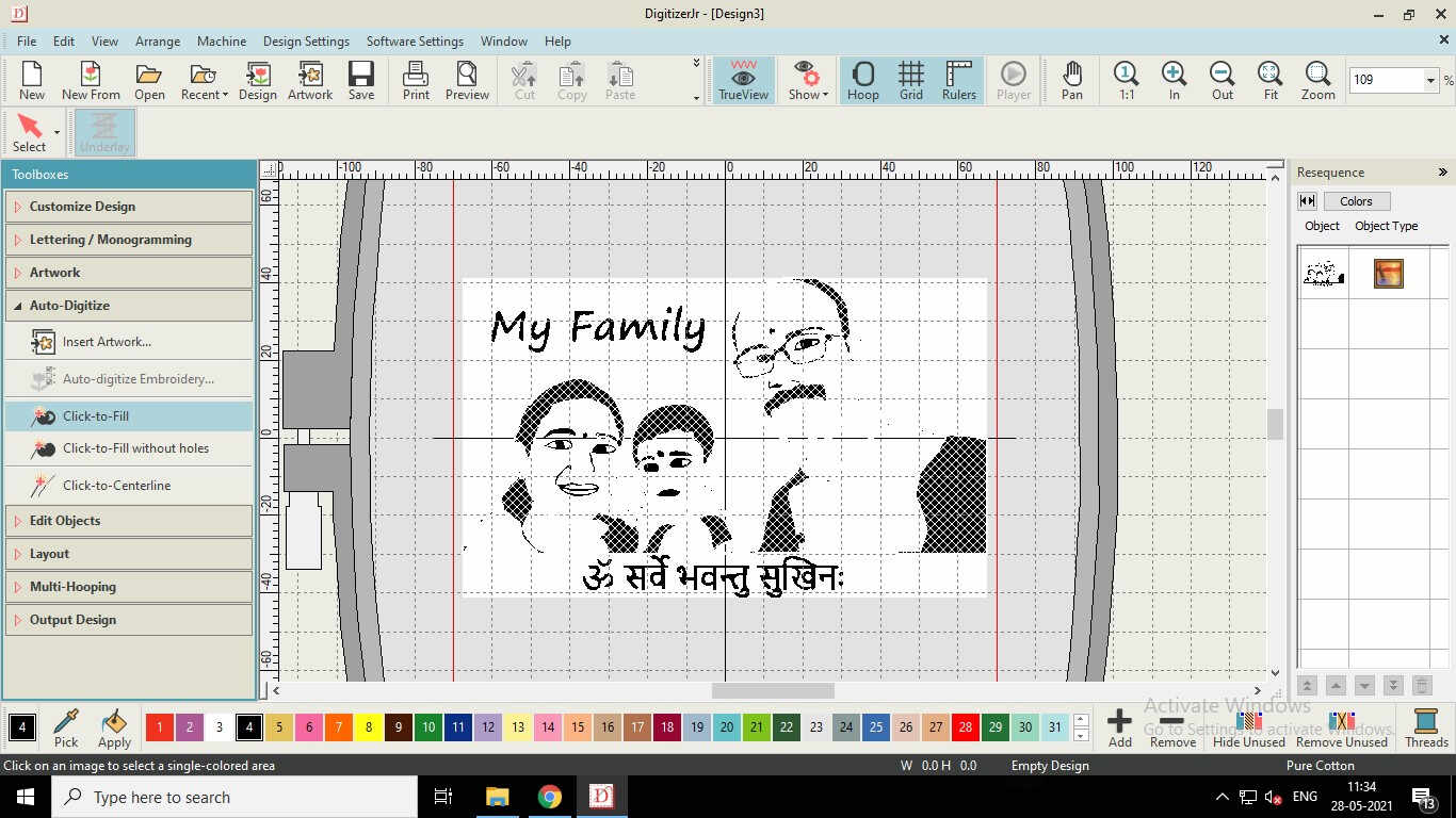
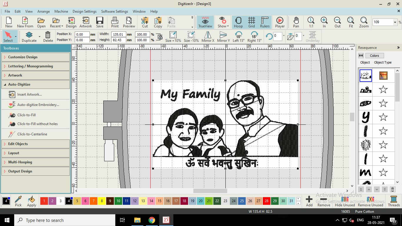
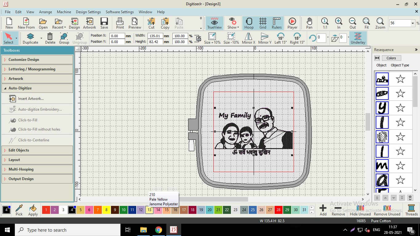
The Bed Size of the Machine is only 140*140 mm. So, if the Size of the selected image is greater than 140 mm, we need to reduce and resize the image to fit in the Red colored frame.
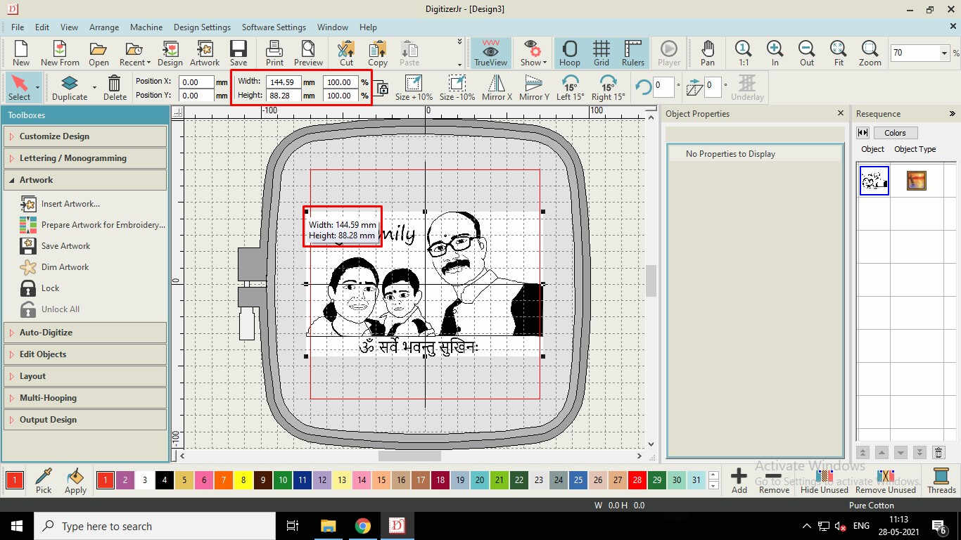
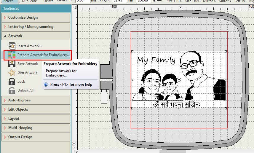
Image after Resizing
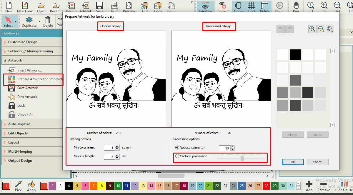
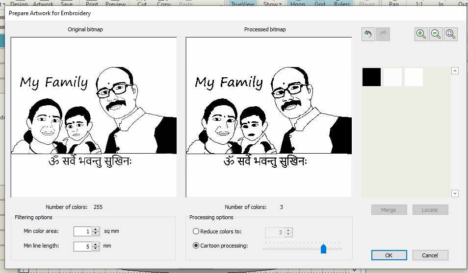
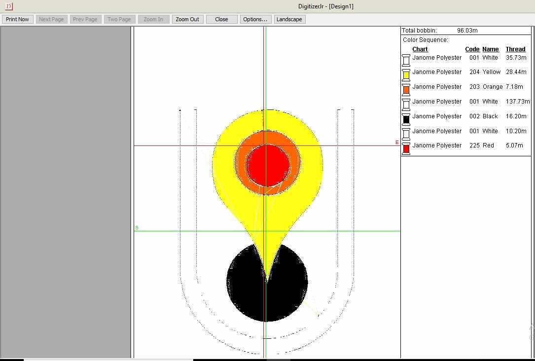
Preparing Artwork for Embroidery
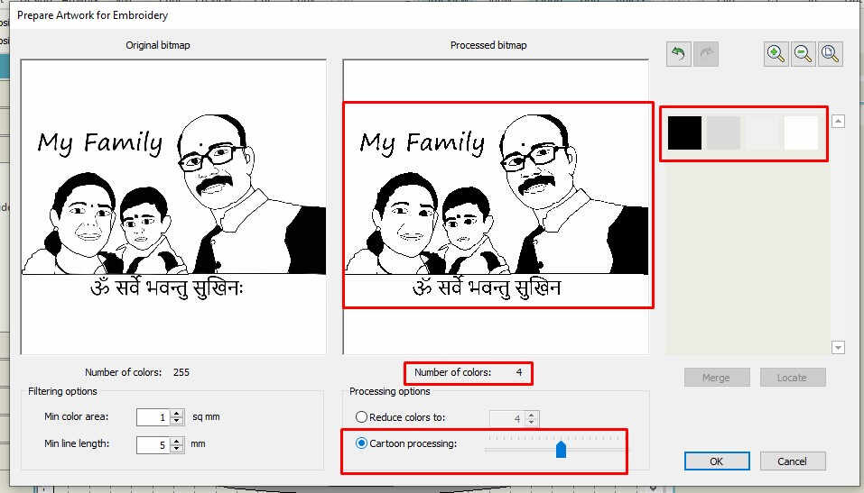
Choose the Best Fit from the Cartoon Processing
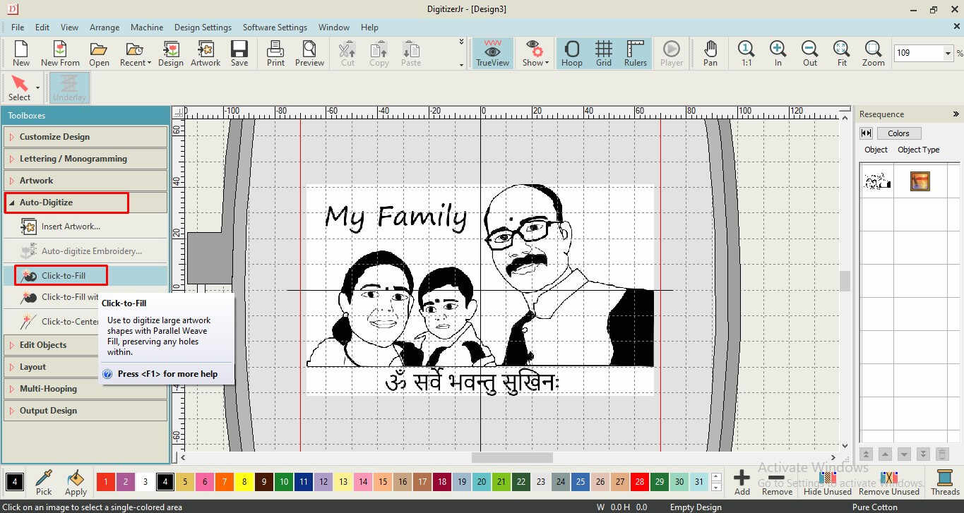
Click to Fill the areas which needs to be Filled with colored stitch
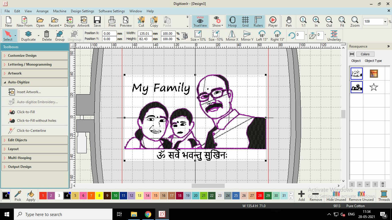
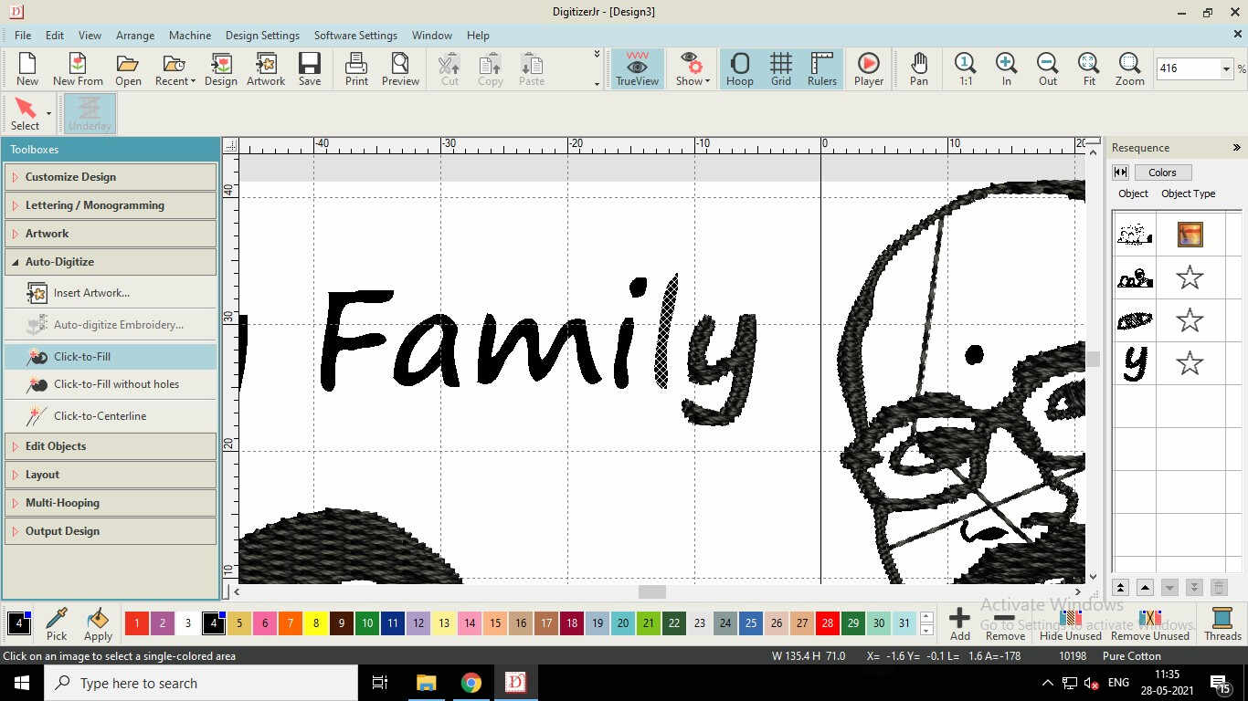
Filled area with stitch would look like this
Colors for the shaded areas could be selected from the pallette below
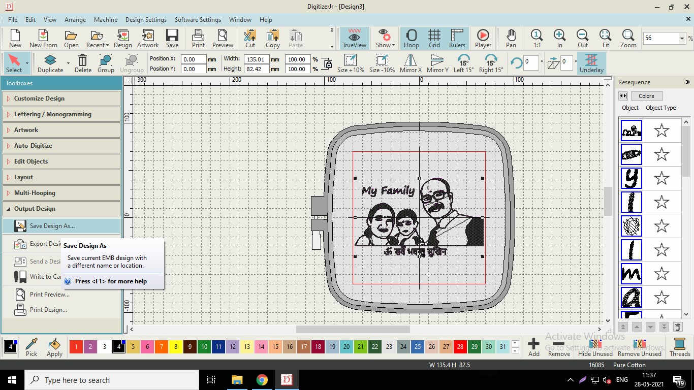
Save the Processed image as ".JEF" file
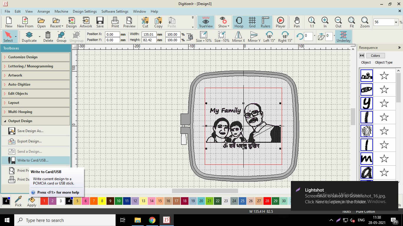
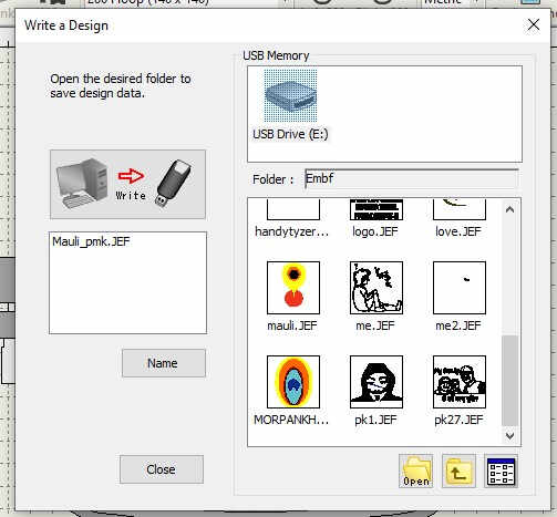
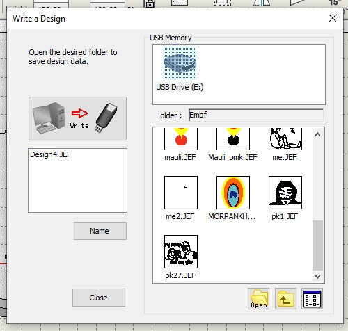
Save and Export the processed file to the USB drive for uploading on the Sewing machine
Also tried to process colorful images.
tried processing the Tilaka/Tikka (Forehead Decor) of Vitthala with colors
 |
 |
|---|
After Saving the File in the PenDrive(USB Drive), plug it in the USHA Janome CNC Embroidery Machine. Select the File for processing. It is an ".EMB" file
Apply the Canvas Paper to the Backside of the Cloth on which the Design is to be printed and Attach the desired area in the center of the Ring. Plug it properly so that the cloth will not have any wrinkles and tightly hold by the clamps. If not, it may come out of the clamps and then the Printing cannot be resumed as the Alignment and Center is lost.
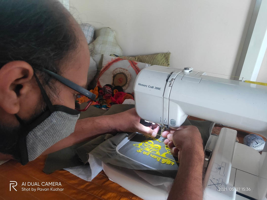
Fill the Bobbin with desired color and place it in the machine. Mount the thread through the 5 loops given on the machine. Mount the Clamps on the machine and Push the Start Button. If the Lever is pulled up, the machine prompts the message to lower it down.
If the Bobbin is out of thread, the machine automatically stops. Carefully remove the Plate from the clamps and remove the bobbin. Fill it up again and mount it. Press the Start Button again to resume. If the thread is cut, cut the front end and mount it through the 5 Loops and through the Needle. Press the Start button again to resume.
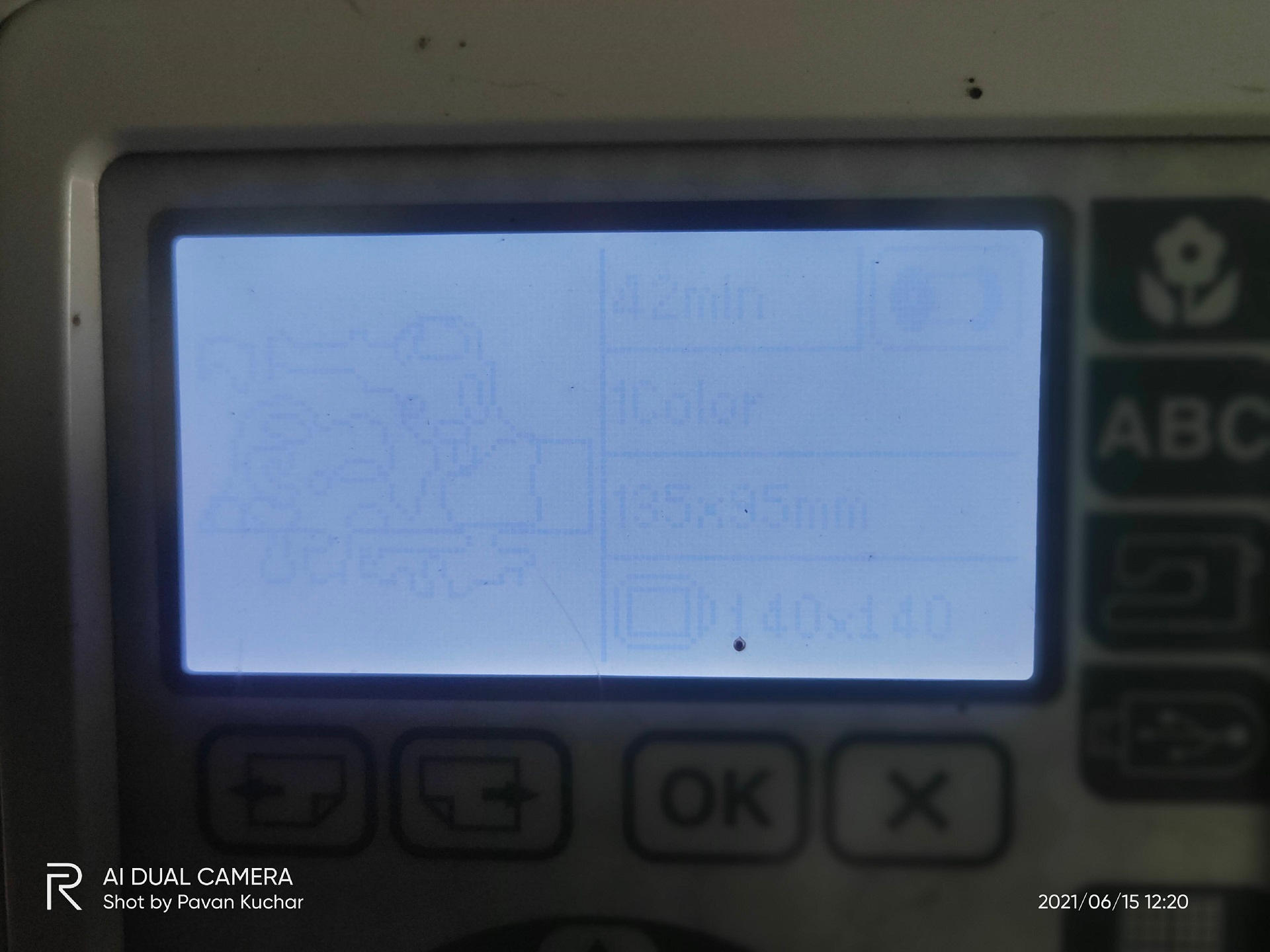
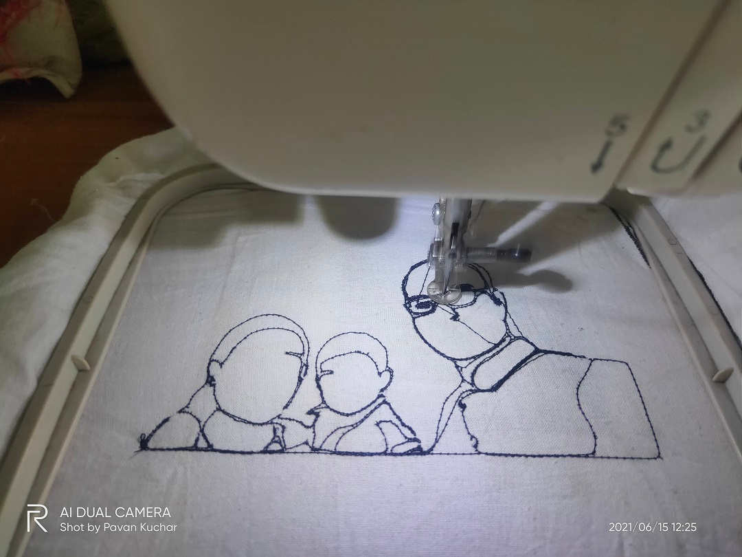
Design in the Machine
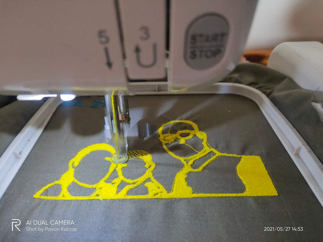
Embroidery is in Progress
Changing the Thread as it was cut in between.
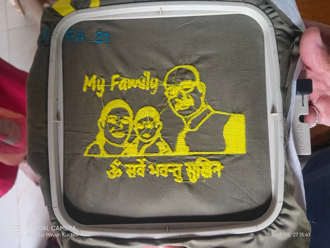
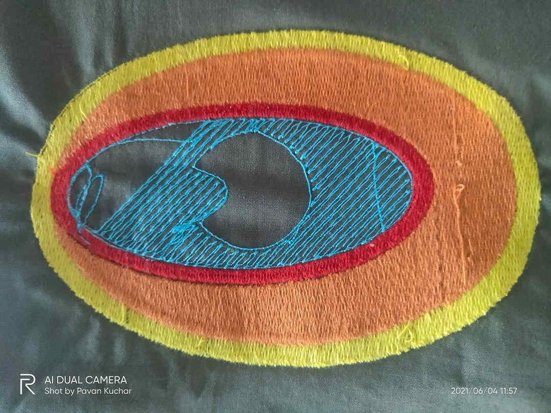
The Image after Embroidery
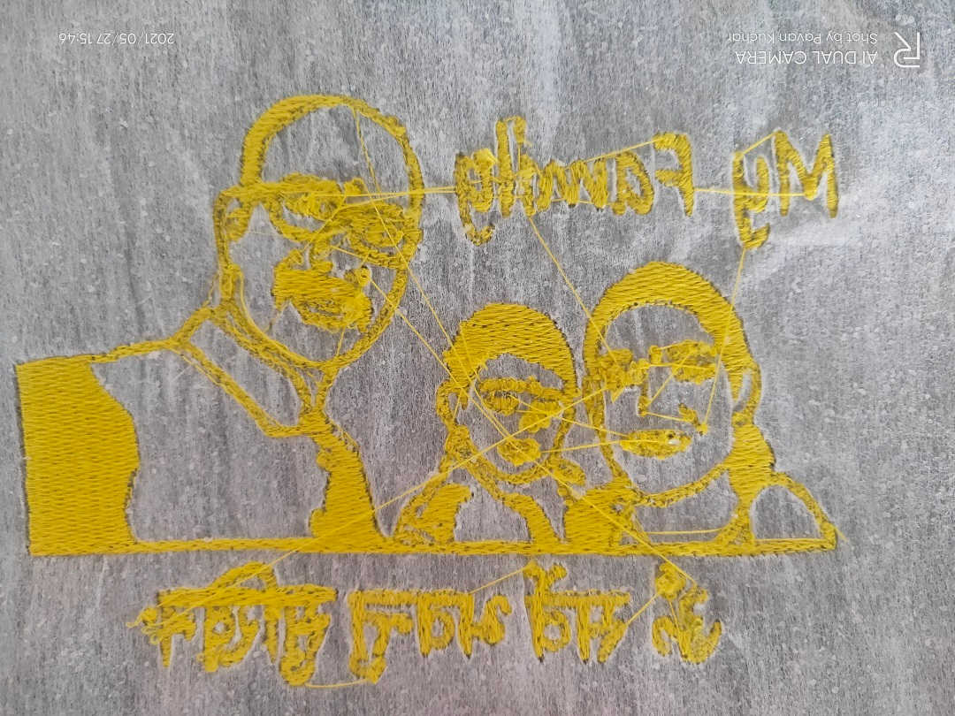
Back Side of the Embroidery
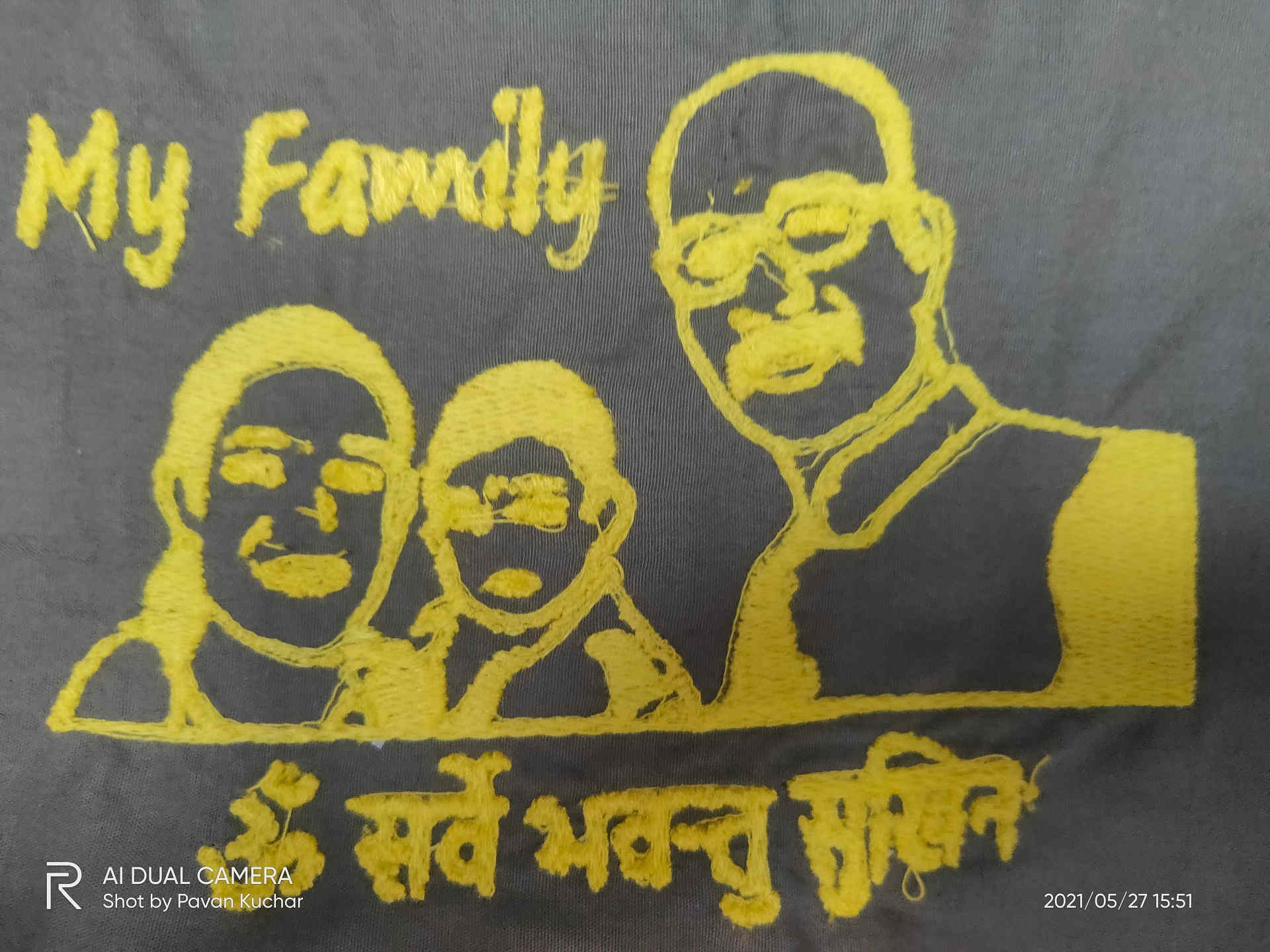
Design after Embroidery
The Embroidery didnt came out as expected. I realized that the image needs to be processed in the Digitizer Software and carefully select the desired and required outlines to be filled. Minutes and details could be only outlined and few objects could be filled.
Tried it on Handerchief. The Outer Lining embroidered by the machine
the Machine and the Embroidery Ongoing
Colored design trial
The thread was broken and the Cloth also slipped from the Clamp. I was not able to locate the center. So, will have to again do the CAM process.
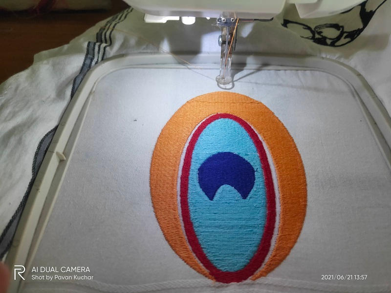 Colored design under Processing | 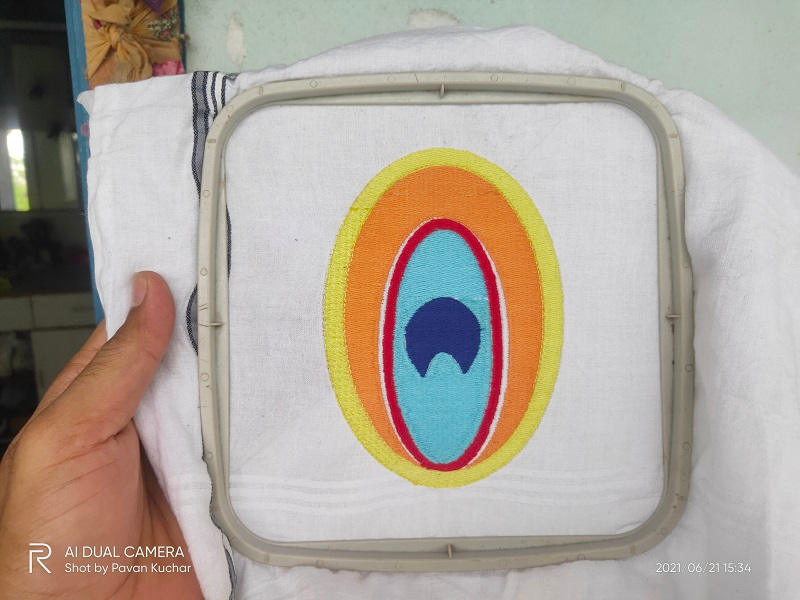 Finshed Embroidery of Colored Design |
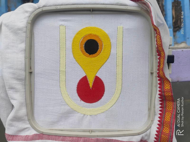 Embroidered Forehead Decor (Tilak) designed by Anand | 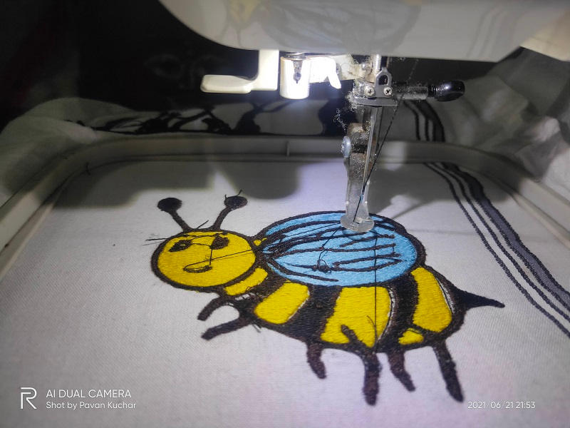 Embroidered HoneyBee designed by Rahul |
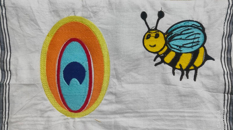
Colored Peacock Feather and HoneyBee
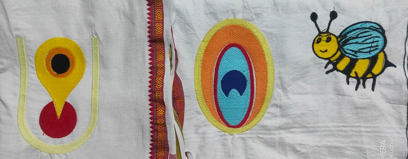
All the Embroidered Designs
Plasma Cutting:
Most of us have decided to use the Plasma Cutter machine for this week. Just like the Laser Cutter, we had to identify the Kerf of this machine for cutting our designs. Also, we needed to study the Technical and Safety specifications of the Plasma Cutter.
We have the Steel Tailor Plasma Cutter in our FabLab.
Plasma Cutting:
Plasma cutting is a process that cuts through electrically conductive materials by means of an accelerated jet of hot plasma. Typical materials cut with a plasma torch include steel, stainless steel, aluminum, brass and copper, although other conductive metals may be cut as well. Plasma cutting is often used in fabrication shops, automotive repair and restoration, industrial construction, and salvage and scrapping operations. Due to the high speed and precision cuts combined with low cost, plasma cutting sees widespread use from large-scale industrial CNC applications down to small hobbyist shops.(Source-Wikipedia)
Working Principle of Plasma Cutter:
The basic process in plasma cutting and welding is to create an electrical channel of superheated, electrically ionised gas – i.e. plasma - from the plasma cutter itself through the workpiece to be cut, thus forming a finished circuit back to the plasma cutter via an earth terminal. This is achieved by a compressed gas (oxygen, air, inert gas and others depending on the material to be cut) which is blown to the workpiece at high speed through a focused nozzle. Within the gas, an arc forms between an electrode near the gas nozzle and the workpiece itself. This electric arc ionises part of the gas and creates an electrically conductive plasma channel. As the current from the cutting torch of the plasma cutter flows through this plasma, it gives off enough heat to melt through the workpiece. At the same time, much of the high-speed plasma and compressed gas blows the hot molten metal away, separating the workpiece.
Parameters of Plasma cutting Machine:
- Type: SMART III
- Input voltage:110/220 V
- Input Frequency:60/50 Hz
- Input power:200 W
- Controller:LCD 7 ˝ color screen controller
- Effective cutting range:1500 (crosswise) X 3000 (lengthways) mm
- Max cutting speed:4000 mm / min
- Max running speed:5000 mm / min
- Machine positional accuracy:0.2 mm
- Repeated positioning accuracy:0.2 mm
- Cutting thickness:Plasma cutting: depends on plasma power
- Cutting mode:Plasma
- Cutting software:FastCAM
We have Steel Tailor's Plasma Cutter in our Lab. I decided about certain designs which could be used in the Vigyan Ashram. It could be a Magazine holder, Key Hanger, Mobile Stand or a Shape of Goat for my Final Project.
Various Shapes designed by me in Inventor are-
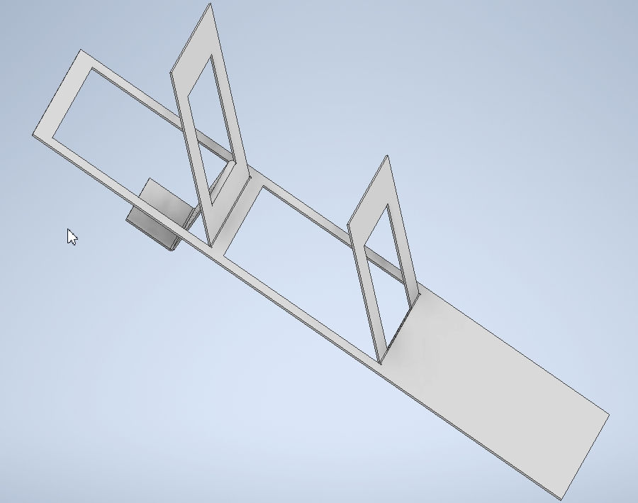
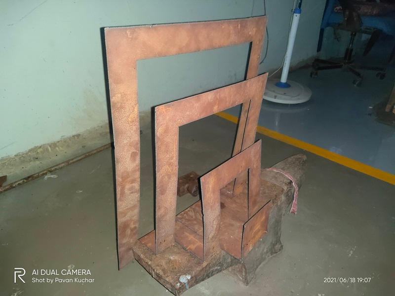
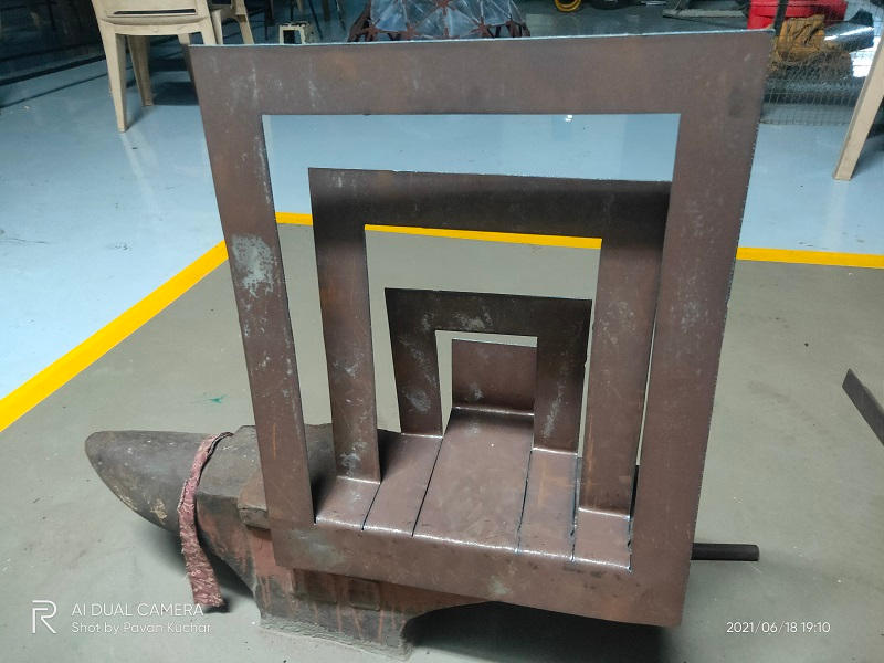
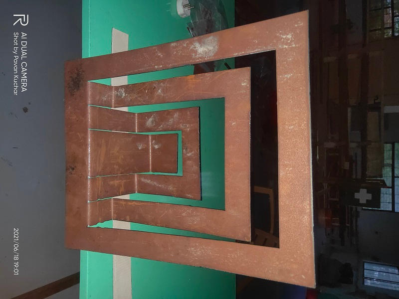
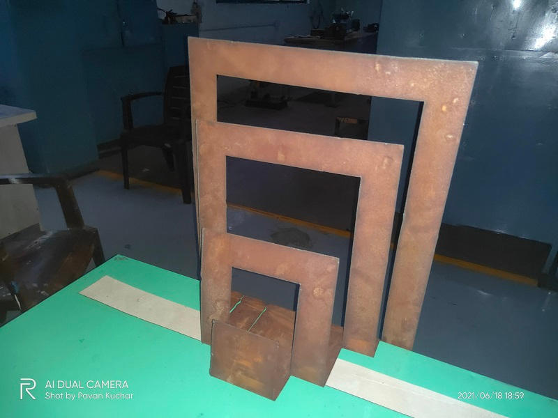
Standing Newspaper and Magazine Holder
Snake shape Keychain Holder
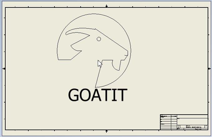
Goat shape for Welding on my Final Project
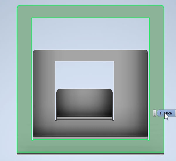 Front View | 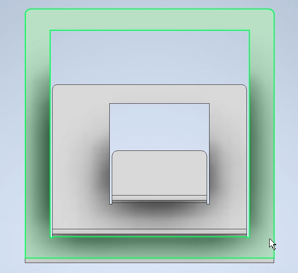 Dorsal View |
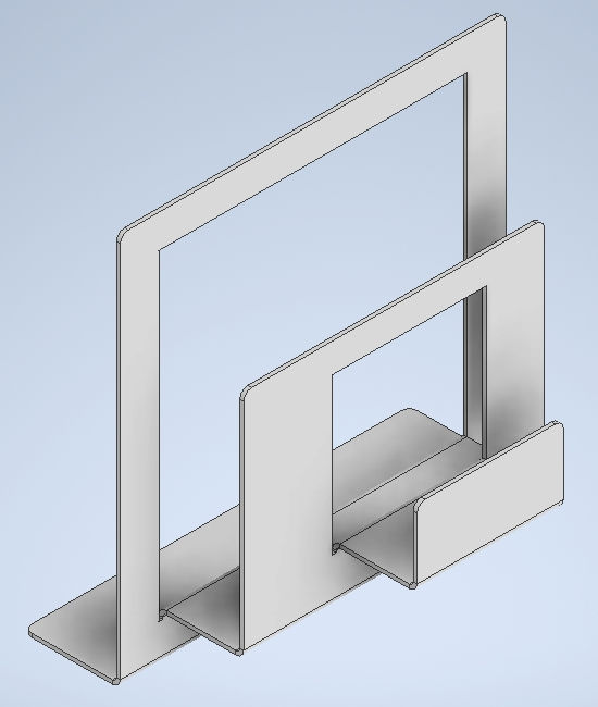 Side View-Back | 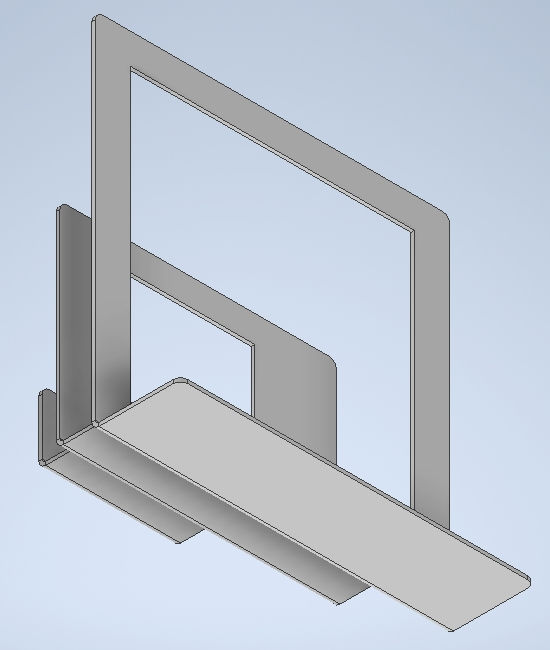 Side View-Front |
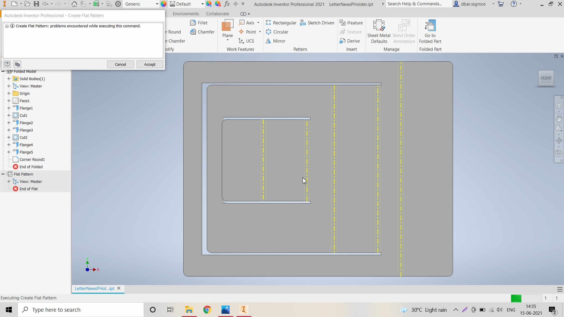
Error in Design after Flattening the design / Metal Sheet
About FastCAM Software for Toolpath Generation:
FastCAM® CAD CAM Software for Plasma, Oxy, Laser and Waterjet is a total NC solution for metal shape nesting and cutting; You can Draw, Path, Nest and Cut from the one system. FastCAM® allows people at a shop floor level to start profile cutting with the minimum of training.For more details click here.
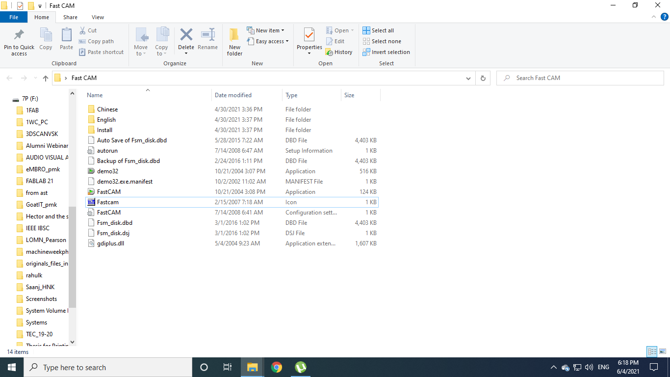
Open the FastCAM software for creating the Toolpath
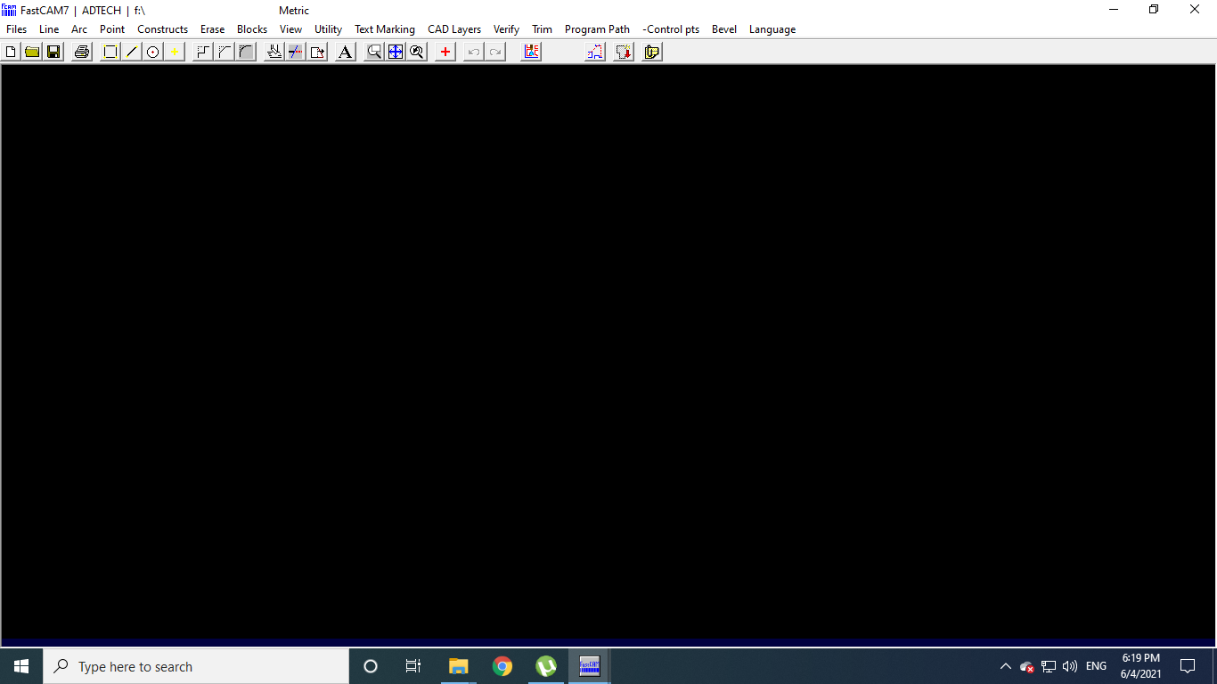
Window of the FastCAM software
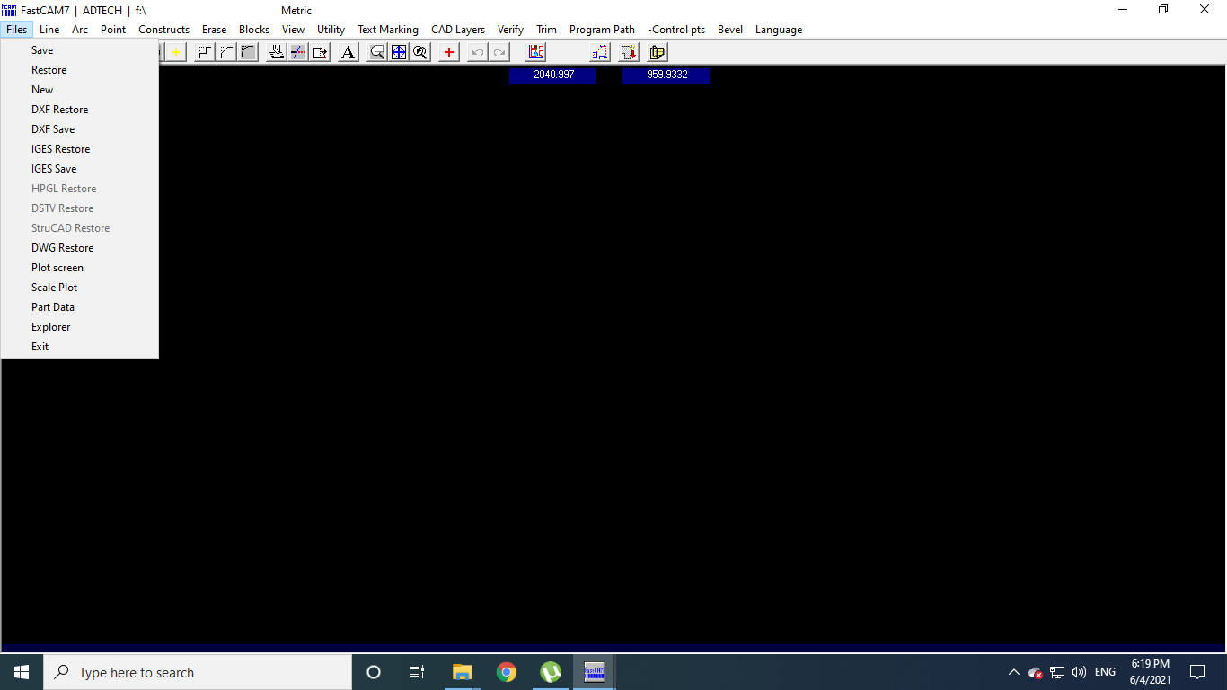
Go to Files and Click on New
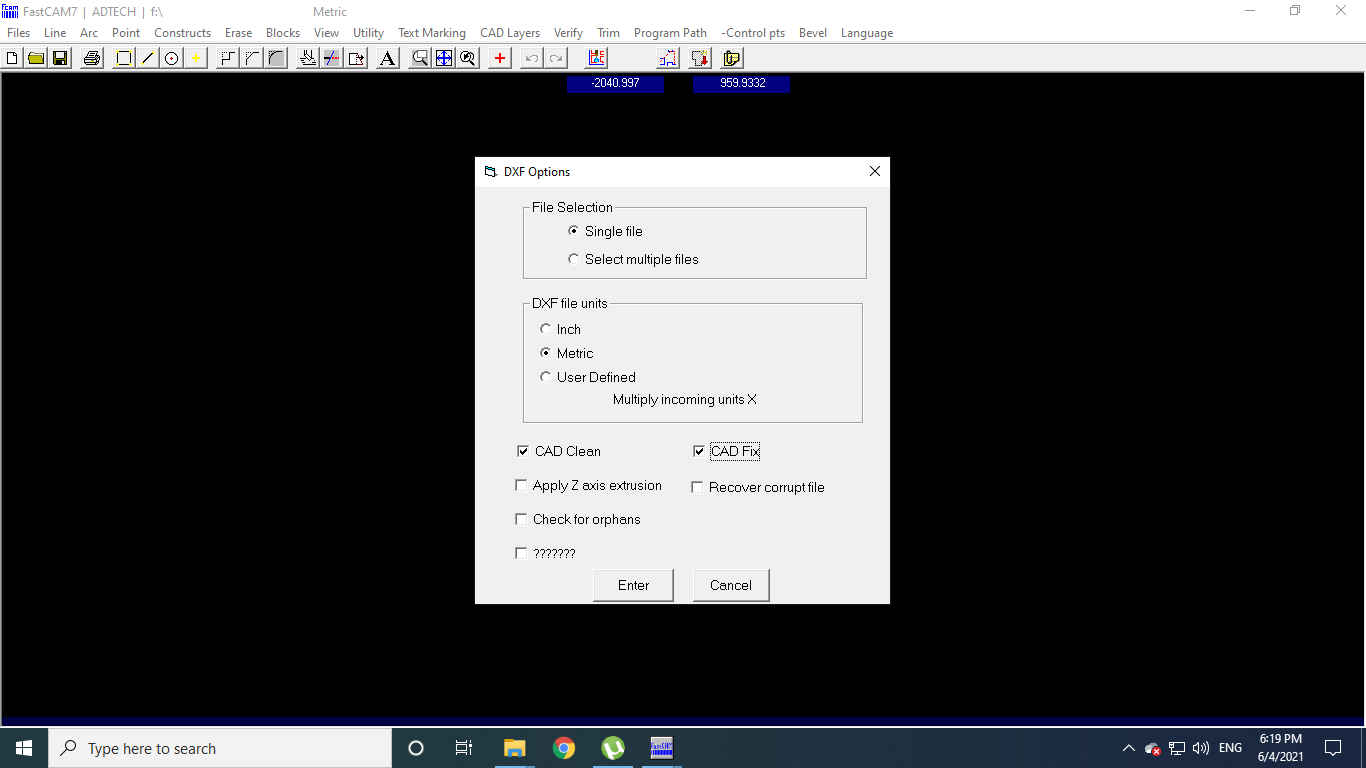
Select the particular Options in the dialogue box and hit Enter
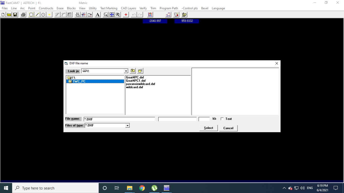
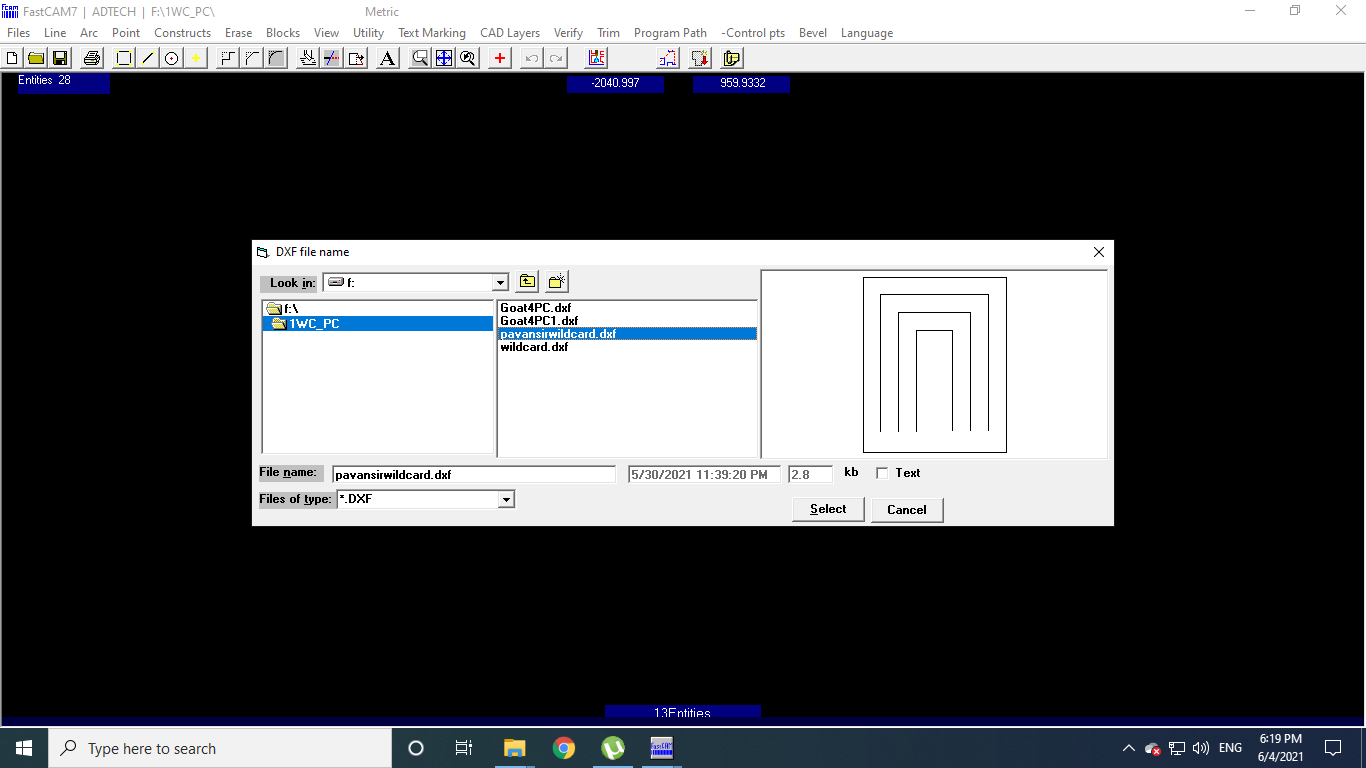
Select the .dxf file which you want to process
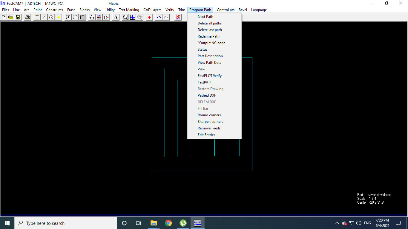
Go to the Program Path
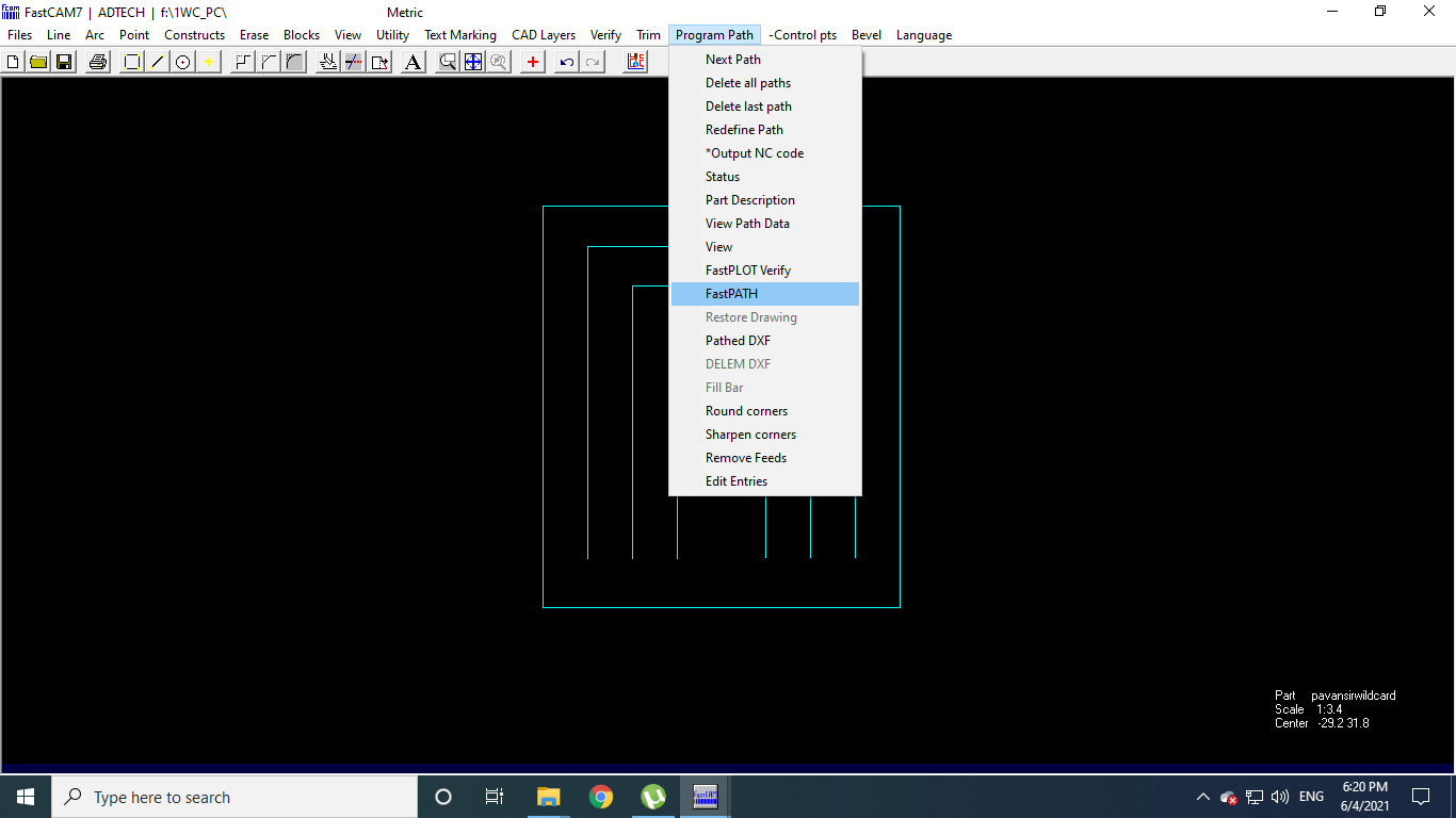
Select the Fast Path
Click on the Start Fast Path
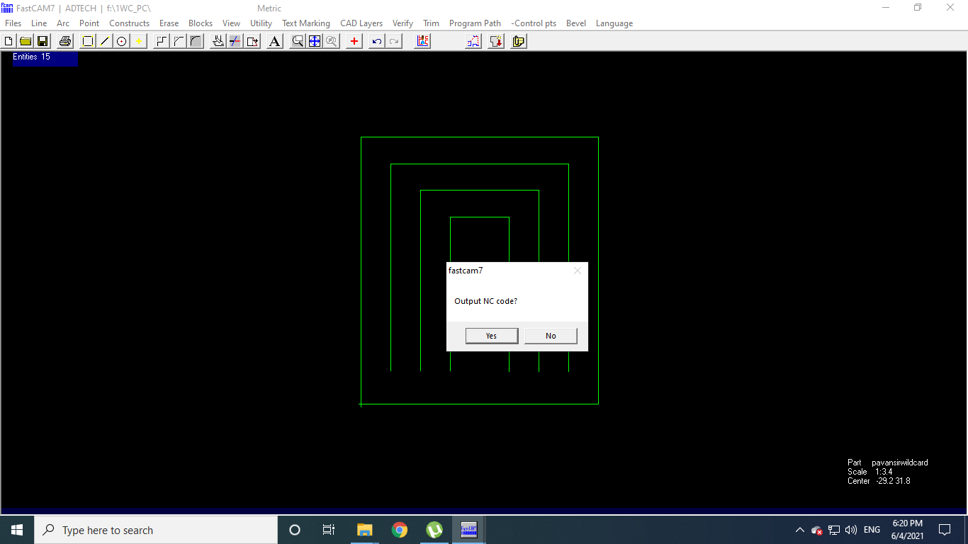
Click on Yes in OutPut NC Node
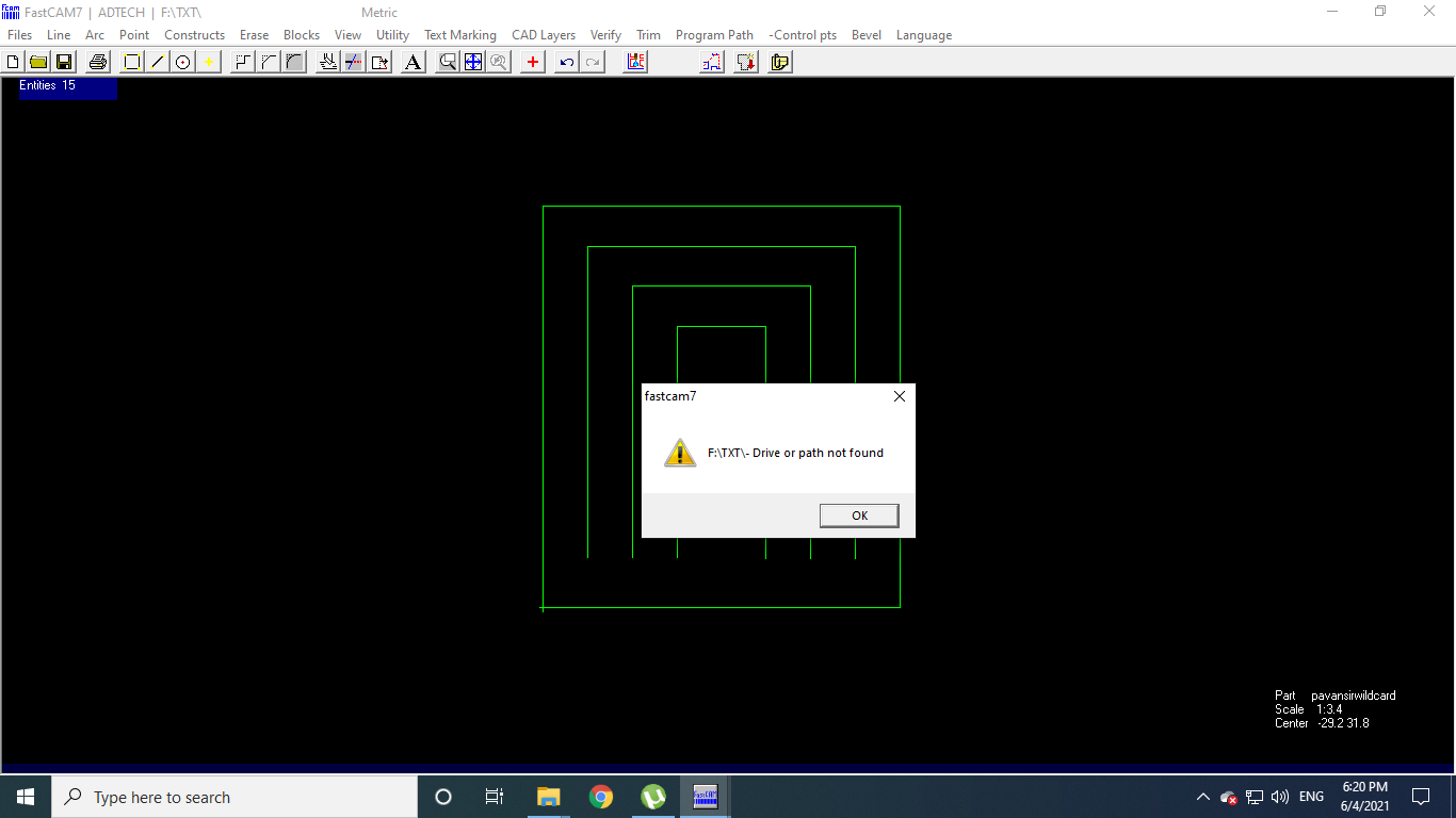
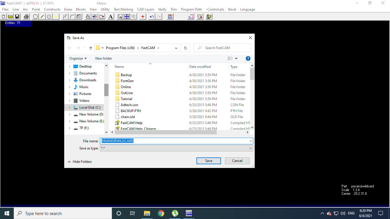
Save the File in desired location
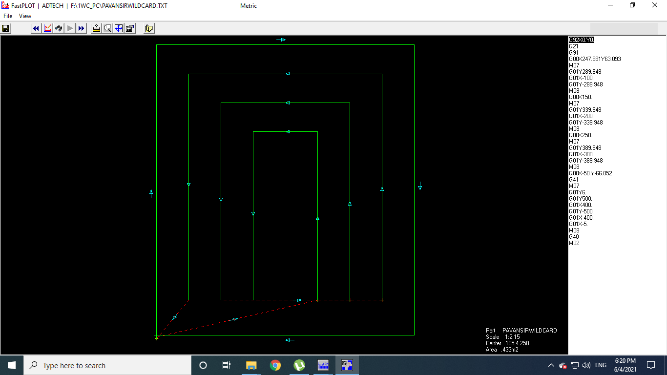
G-Code and ".TXT" file is created for Plasma Cutting
Before Plasma Cutting:
The details of Kerf Calculation could be found on the page of Anand Tale.
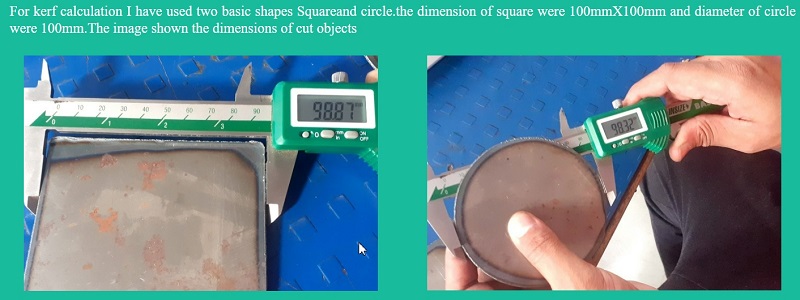
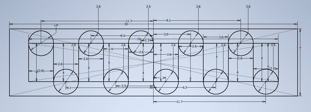
Kerf Calculation done on basic Shapes of Square and Circle
PreRequisites and Settings:
- Material used:Metal sheet of "CRCA"
- CRCA :Cold roll closed annealed
- Thickness of metal sheet :0.8 mm
- Air pressure:7 Bar
- Current set at:30 Amp
- Voltage Supply:320V three phase supply
- Kerf:1mm
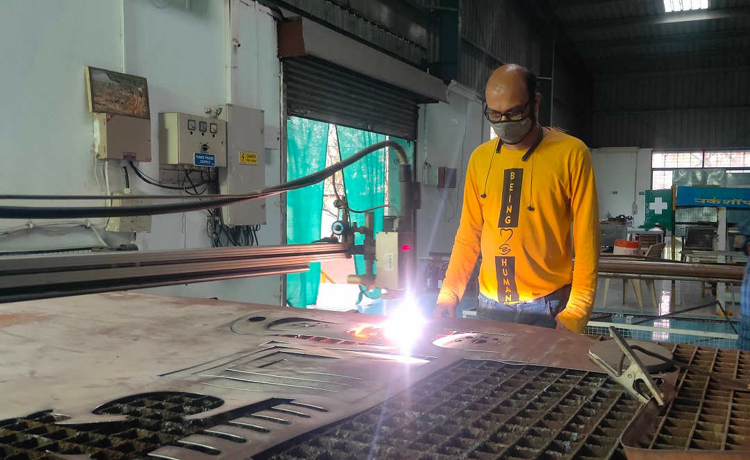
The Plasma Cutting Ongoing
Video Stream of Plasma Cutting:
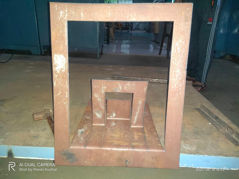
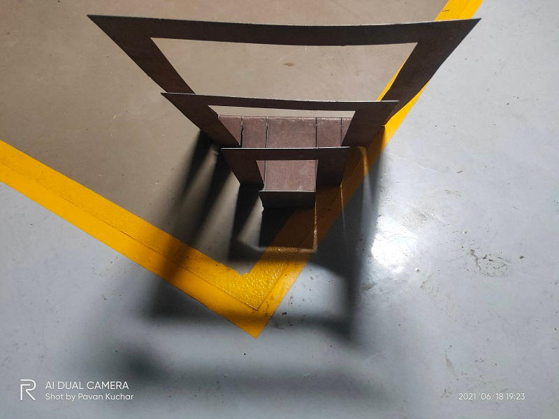
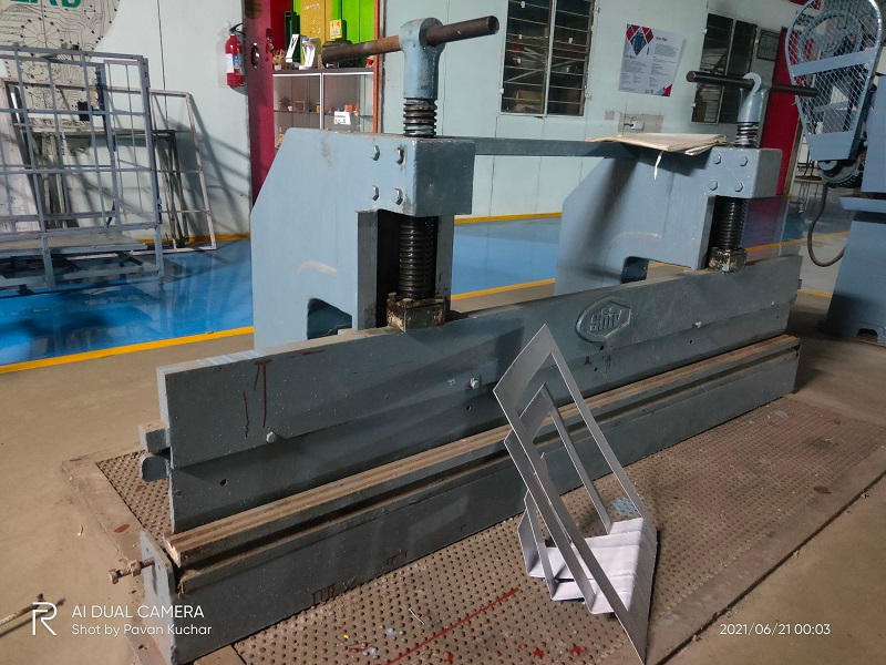
After Plasma cutting, I used the Bending machine, Hammer and Anvil to give shape to the Metal sheet.
 |  |
|---|---|
 |  |
 |  |
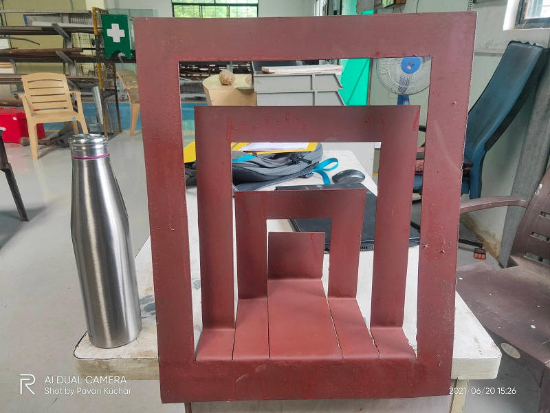 Applied Anti Rusting Red Oxide Primer | 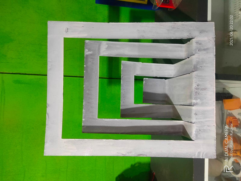 Painted in White Oil Paint |
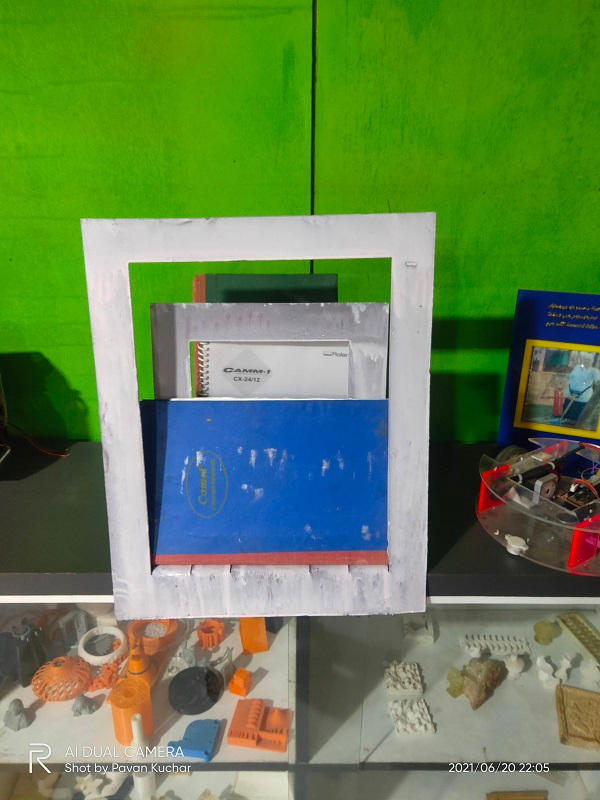 Shelf and Magazine Holder | 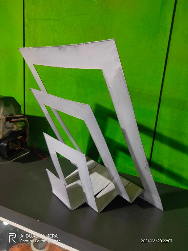 Could be used as Seperator as well |
|---|
Summary:
In this week,
- I learned about the Digitizer Jr V5 Software for creating Toolpath for Embroidery designs.
- What I experienced is that the Simpler and less complex the 2D design, the Embroidery is better, but if the design is complex and more curvy, it has lesser finishing in the embroidery.
- Proper selection of Outline and filling the patches is necessary while creating toolpath.
- The thread should be of good quality or else it breaks midway.
- I learned about the FastCAM software for the Toolpath creation for Plasma Cutting
- The Plasma cutter cuts the basic and rectangular shapes with ease and cleanly but the curves take more time. Smaller details take longer time to cut. Kerf should be calculated and added to the design for better cutting.
- Set the proper Power and Speed while cutting the metal sheet. Also, remember to attach the earthing to the metal plate.
Downloads: Original Files
You may find here the designs that I used in this Assignment.