
Send a message between two projects.
Link to Group AssignmentDesign, build, and connect wired or wireless node(s) with network or bus addresses.
Assignment Requirement
Status
Linked to the group assignment page
Completed
Documented your project and what you have learned from implementing networking and/or communication protocols.
Completed
Explained the programming process(es) you used.
Completed
Outlined problems and how you fixed them.
Completed
Included design files (or linked to where they are located if you are using a board you have designed and fabricated earlier) and original code.
Completed
Included a ‘hero shot’ of your network and/or communications setup.
Completed
For this assignment I reviewed Adrian Torres's networking processes, specifacally I2C (Inter-Integrated Circuit). I2C is a synchronous, multi-master/multi-slave, single-ended, serial communication bus. It is a means of communicating with multiple devices.
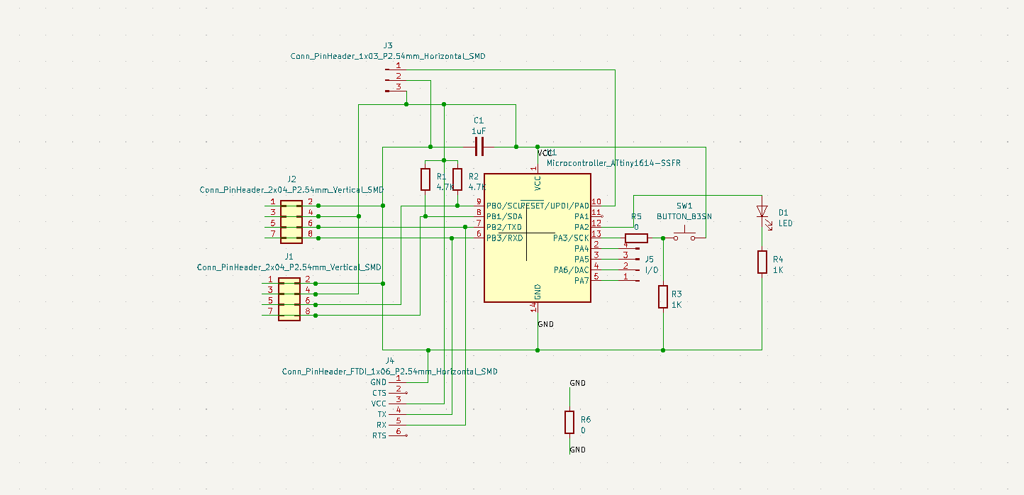
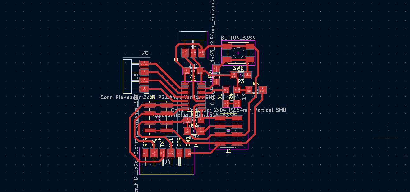
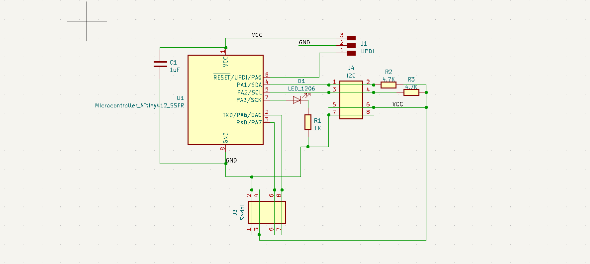
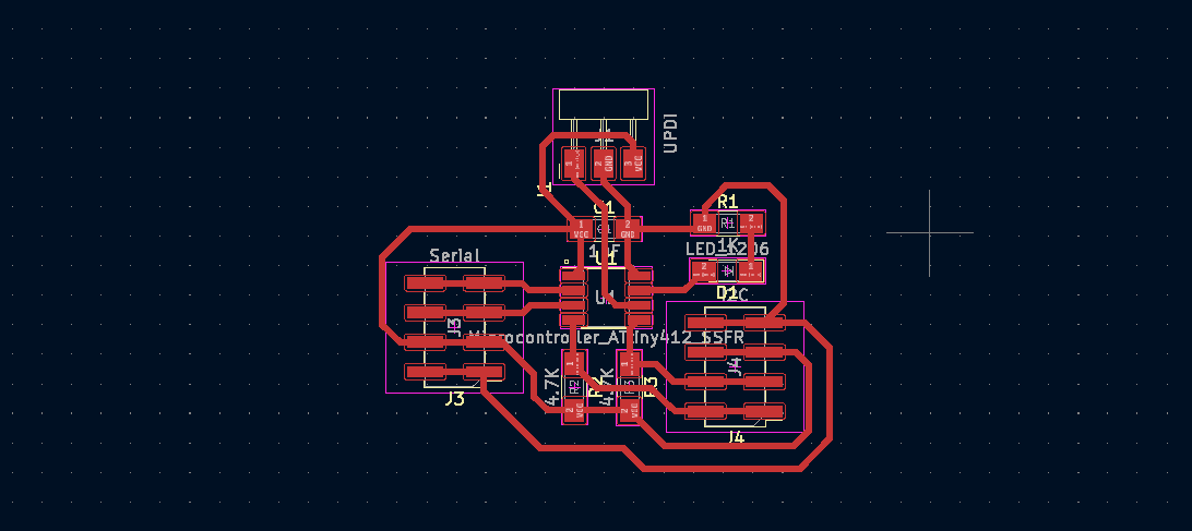
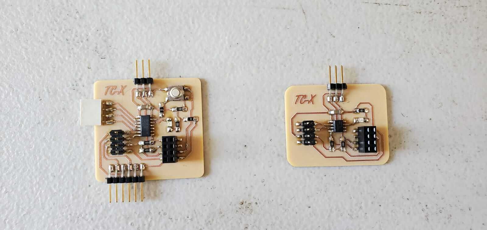
I designed two microcontroller boards that are not limited to this assignment. The boards were designed with with ports for both UART and I2C connection and communication. The master/bridge board contains an ATTiny 1614 microcontroller and the slave/node contains an ATTiny 412 microcontroller.
This board includes:

This board includes:
For the programming, I used Adrian Torres's I2C programs for both the Master and Slave boards.
This program contains a for loop which increments by 1. This value is sent over the I2C bus and if this value matches the condition containing the address of a Slave board, the signal will be sent to that Slave board and its LED will flash. Adrian's program generates 4 values, however I only connected one Slave board.
            //original code by Luis Diaz
//Fab Academy 2022
//Fab Lab León
//ATtiny412 master I2C

#include

int i = 0;
int j = 0;

int led = 4; //led pin

void setup() {
  Serial.begin(115200); //speed of the communications
  Wire.begin();

  pinMode(led, OUTPUT); // led
}

void loop()
{

  for (i = 0; i <= 3; i++) { // 0,1,2,3

    Wire.beginTransmission(8); //slave number 8
    if ( i == 2) {
      Wire.write(1);
      Serial.println("1");
    } else {
      Wire.write(0);
      Serial.println("0");
    }
    Wire.endTransmission();

    for (j = 0; j <= i; j++) { // blink i times
      digitalWrite(led, HIGH);
      delay(200);
      digitalWrite(led, LOW);
      delay(200);
    }

    delay(1000);
  }

}
This program includes an address that when matches the signal or message sent by the Master, its LED will flash.
            //original code by Luis Diaz
//Fab Academy 2022
//Fab Lab León
//ATtiny412 node 1 I2C

#include
int d1 = 0;
#define led 4

void setup() {
  pinMode(led, OUTPUT);
  Serial.begin(115200);
  Wire.begin(8);     //change address for the nodes in my case I use 8 and 9.
  Wire.onReceive(recieveEvent);
}

void loop() {
  if (d1 == 1)
  {
    digitalWrite(led, HIGH);
  }
  else
  {
    digitalWrite(led, LOW);
  }

  delay(500);
}

void recieveEvent(int howMany)
{
  while (Wire.available())
  {
    d1 = Wire.read();
  }
}