Third Week:
Computer-Controlled Cutting
To this weekly assignment we had to design and cut a parametric press-fity construction kit which can be assembled in some different ways and being carful about some important parameters: Kerf and Tolerance, but before that let me tell you about the machines.
The machines
The lab has 2 optimal machine for this assignment.
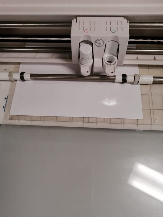
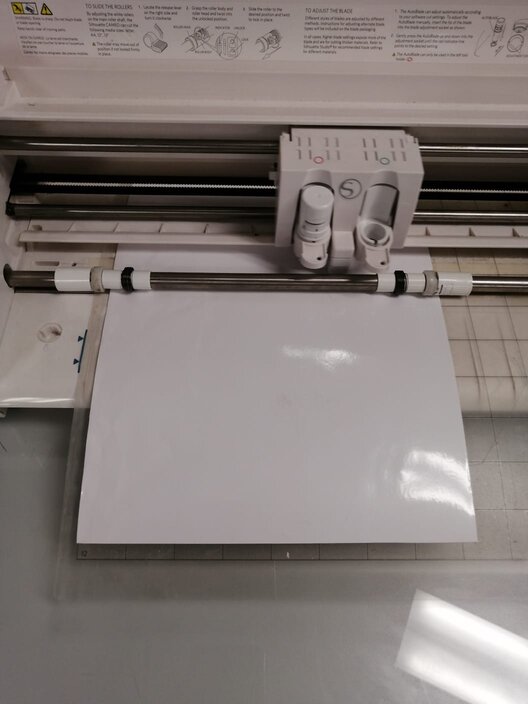
1st) Vinyl cutter: This is the "Silhouette Cameo" which can be use to cut vinyl in A4 Bond format as maximun. It uses adhesive rolls and it's mostly used to make some stickers.
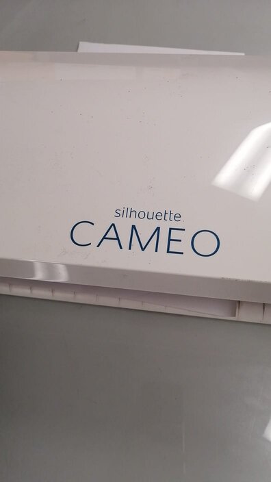
This machine is easy and practical to use. And its software interface accept .dxf format.
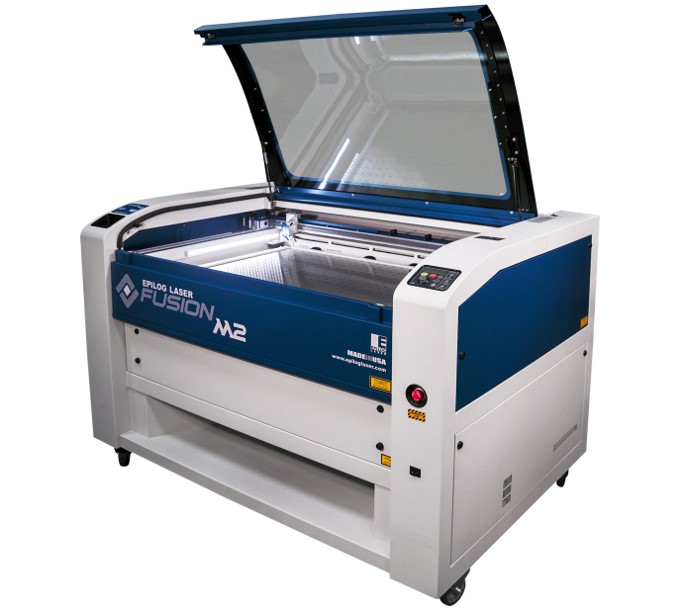
2nd) Laser Cutter: The main machine for this assignment, I think. It's a "Epilog Fusion M2 40". It cuts MDF 3-4mm, acrylic 3mm, and corrugated cardboard.
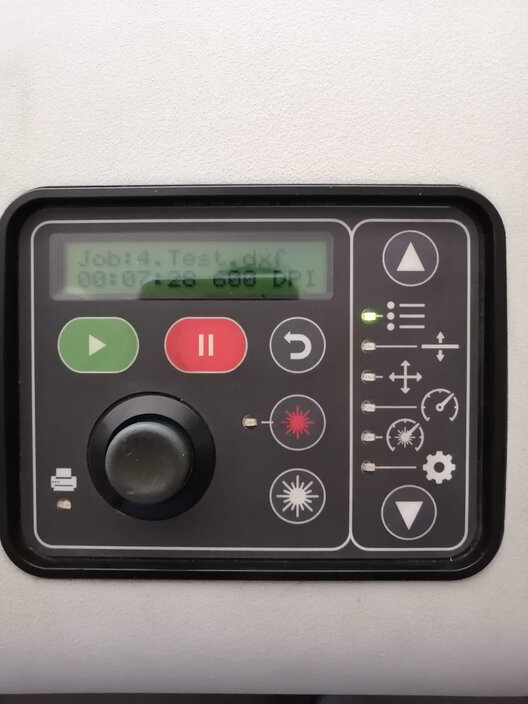
And its panel control:
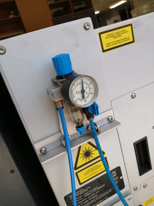
This machine is based on CO2 which is use to guarantee the laser does not have any interference all way through until it hits the material's surface. Due to, we have to keep an eye on its pressure gauge when we open its valve as it will be showed in the next pictures.
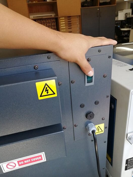
1st we open the pressure's valve.
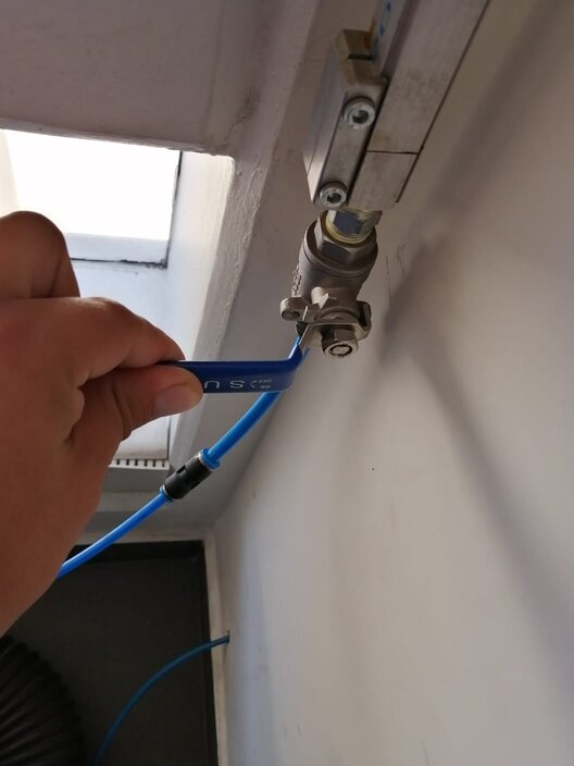
2nd we have to check constantly all pressure is safe to work.
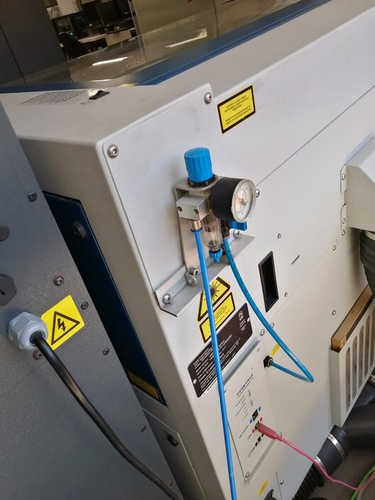
Another thing very important of these kind of machines are extractors which make possible the extraction of gases and smoke produced by manufacturing process.
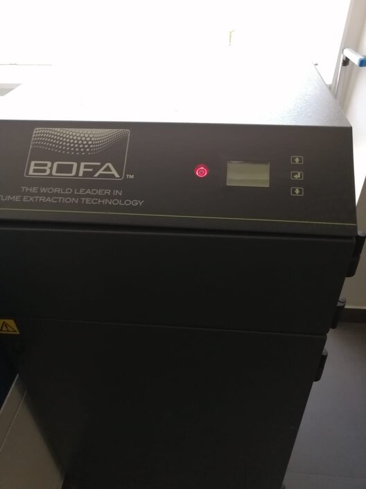
This machine has 2 devices which are the same and work together: The Smoker Extractor.
And The Air Extractor, which is near to Epilog machine.
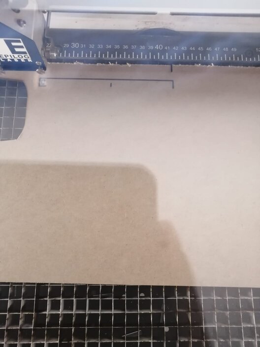
The thickness of the laser light is around 0.001 mm and its tolerance is 0.2 mm.
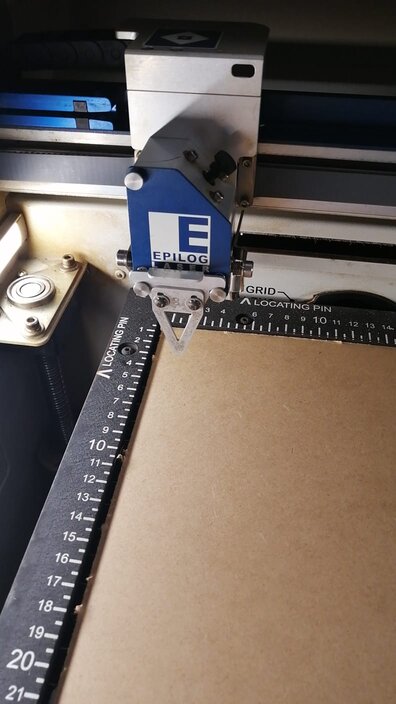
It has another parameter, the Z-Axis, which define if you will cut or print. Its calibration is made with help of a peculiar tool, that triangule which is screwed on laser's head and its calibration process is manual where you have to make that triangule touch the material's surface.
Next important thing about laser cutting machines is the relation about speed and power. Let me explain these 2 concepts: The speed is related with machine's movement and it's mesuared in percentage, our lab machine has 700 mm/sec as his maximun speed. Finally, he power is related with laser intensity and it's also mesuared in percentage, and in our case its maximun power is 40 Watts as 100%.
Now, next image will show you the relation between these concepts.
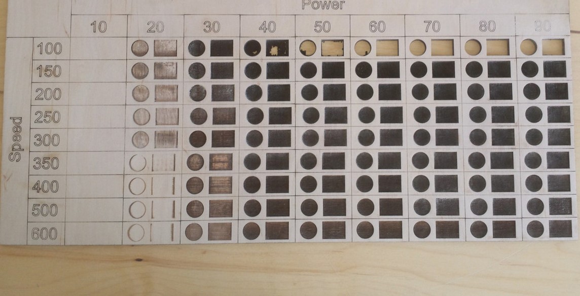
Note: More power and less speed means you will cut something. The oppositve relations is to print.
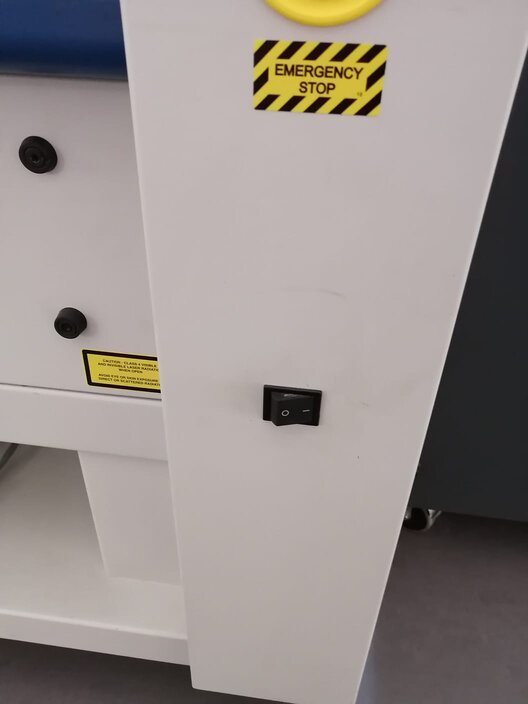
Finally, a very important thing is the emergency stop button which is on right-botton side of the Epilog machina and is in red color with a yellow "Emergency" button.
Both machines require .dxf formats to impress and/or cut.
Vinyl cutting
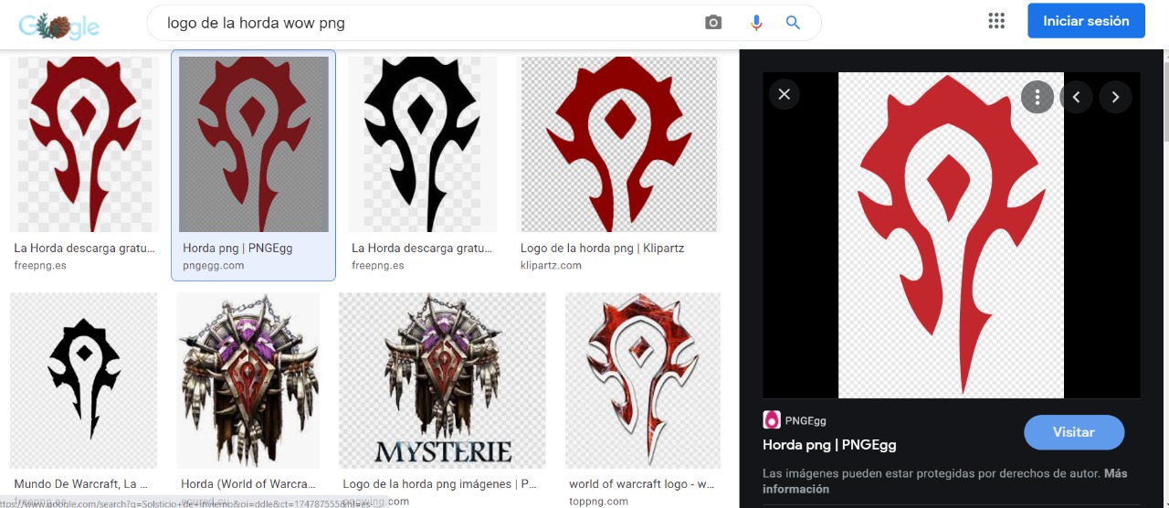
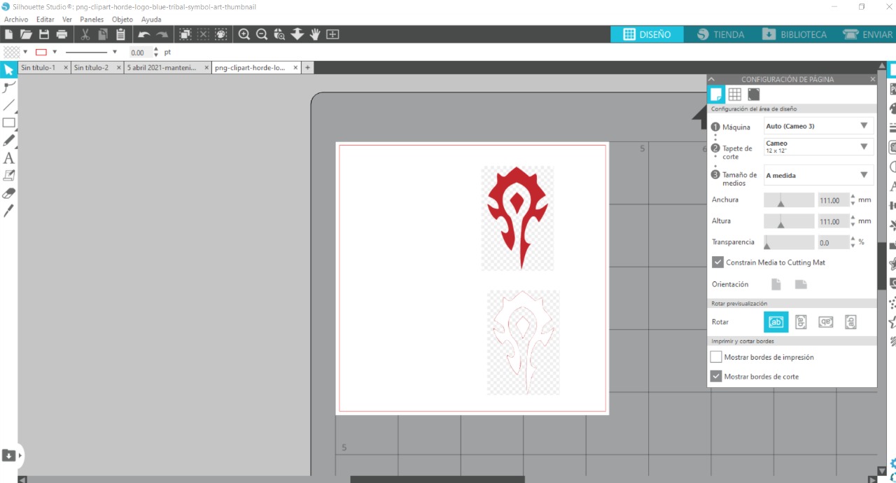
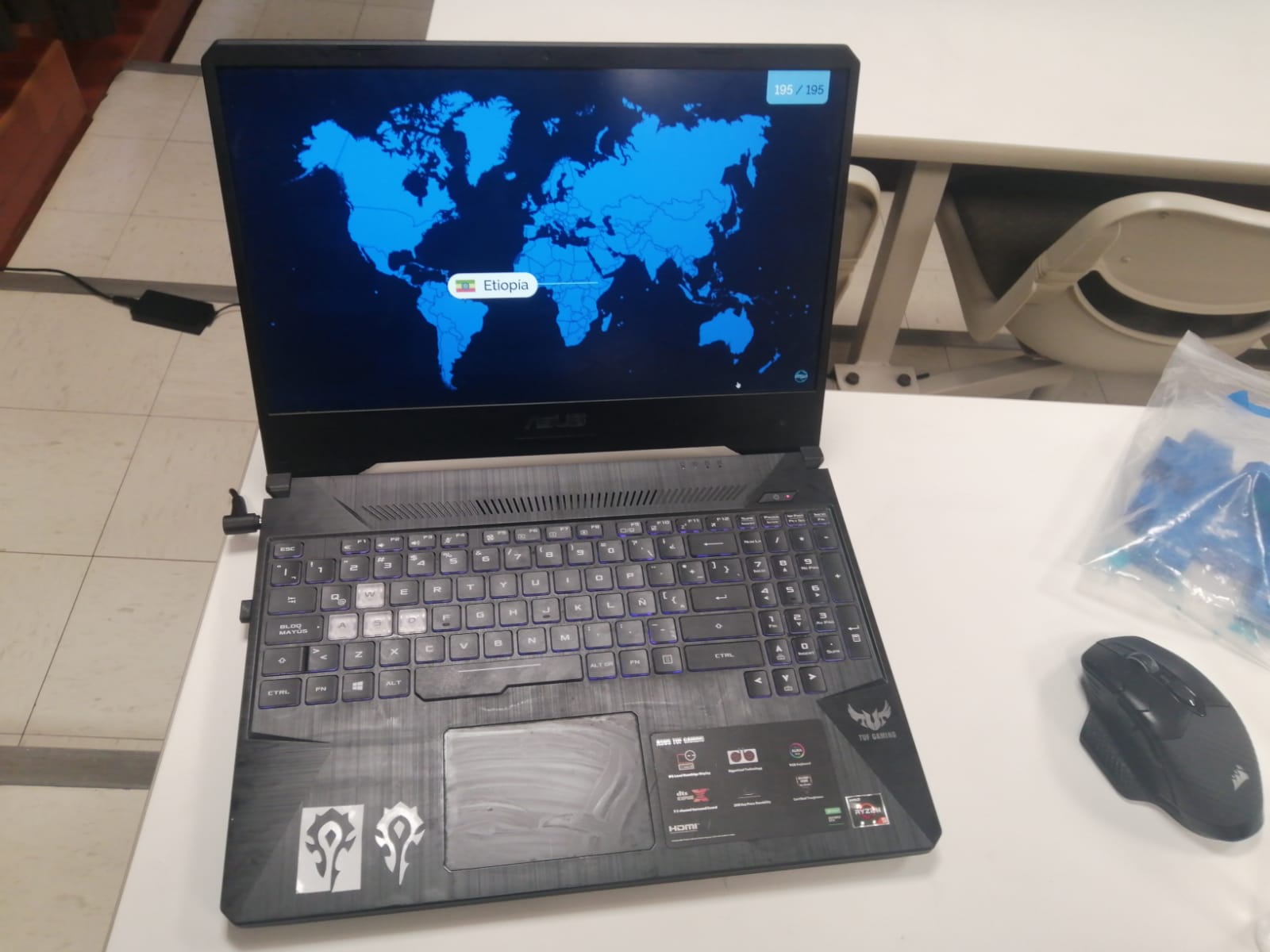
To this part I thought to use import picture from Google about Horde from the Universe of Warcraft. Let's take a look of my test.
1st. I used a the next picture, it's from one of my favorites videogames:
Having import it you will have the next screen.
Then we just have to go to "Send" screen. There you have to select 2 parameters: Pressure and Speed.
Pressure refers to the deepthness of the tool and how it will perform and Speed to the speed of the axial movenment of the tool to cut the material.
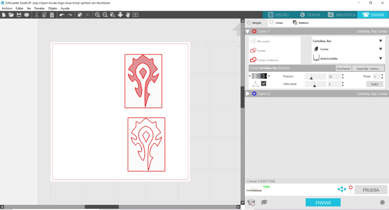
After setting this we just have to click on "Send" on the bottom part to start the cutting process.
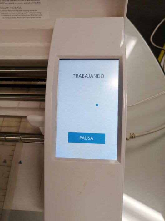
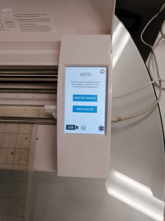
Finally,when the process is done you'll have this message at the machine's screen which translating means DONE or COMPLETED.
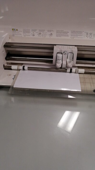
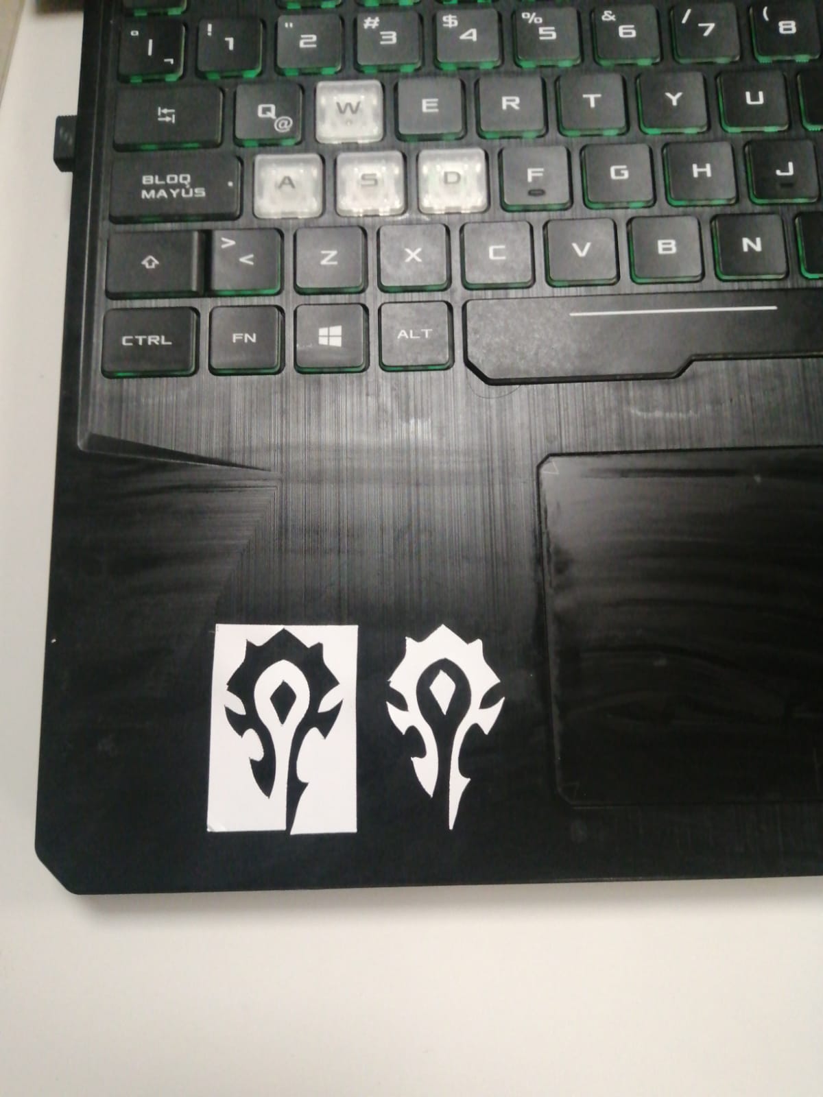
And your product will be like this.
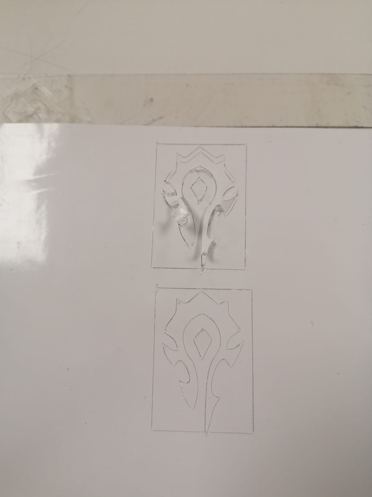
Now we just have to clean it and stick it wherever you want.
Laser cutting
To this part I had to design a parametric figure which can be easly assembled. I used Fusion 360 but I had to watched some tutorials where they teach you how to create parameters and make something parametric. Let's see.
First I praticed trying to make something parametric. I made a mess at first and I couldn't finish this work.
Then I experimented much more with this option. I created a piece which has few parameters to change.
Then I revolted it to create a kind of wheel.
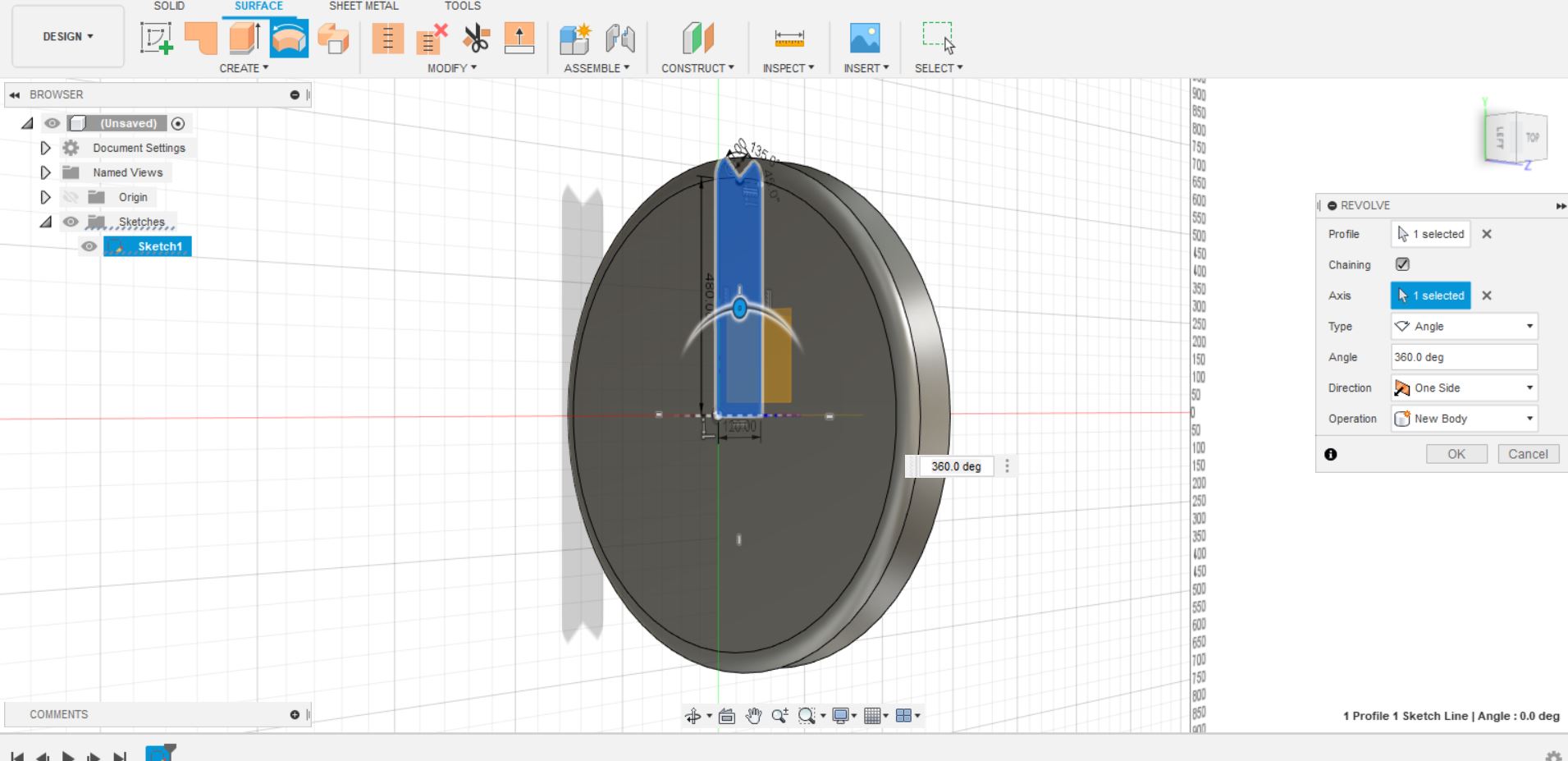
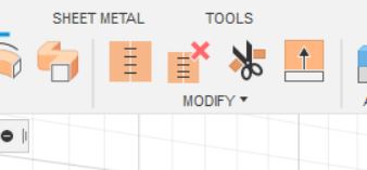
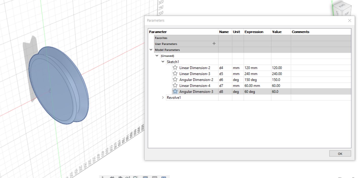
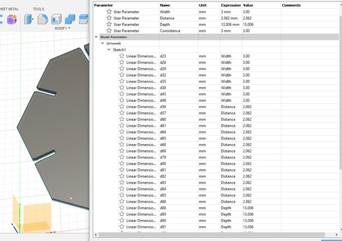
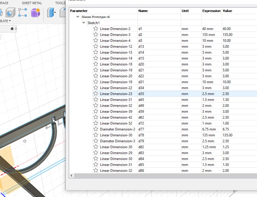
Now I pressed on "Modify" section and selected the "Parameters" option.
When you press this option this window will appear. Here are all the parameters of you piece or project.
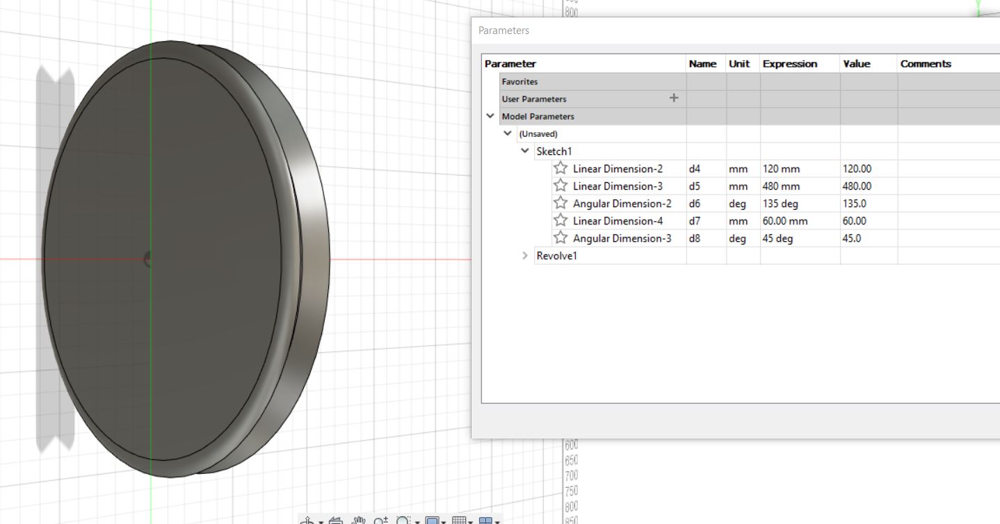
With this window you can change some parameters as distance, angle, thicknees. It has the option to select the especific units.
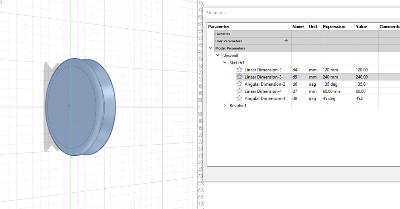
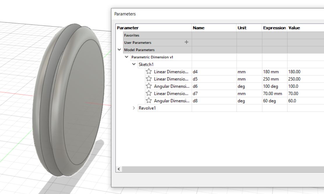
In this example I changed some unit and all the especific parameter of this 3D structure was changed.
To finaly has this.
After the training...
After all this practice I decided to start with a parametric piece.
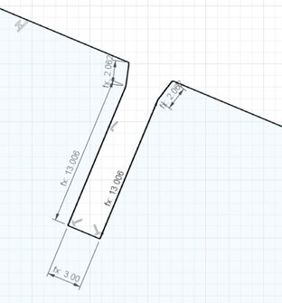
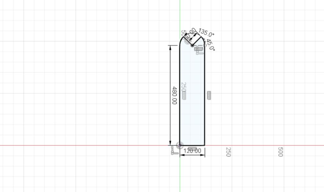
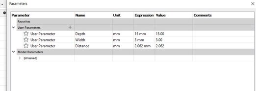
I started setting my own parameters in "User Parameters" as you can see in the next picture, I mostly used 3: Depth (distance between further point to the closet part), Width (as the espesure of the material which is 3mm) and the distance (calculated with formula and refers to the sloped entrance).
Now I started sketching and drawing. Before you define the parameters as usually do, ingressing the distances or angles, you have to put the preset parameters which its names as in my case "Depth", "Width" or "Distance".
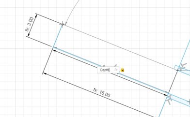
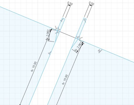
Note: You can chack if you are doing well looking the "fx: ####".
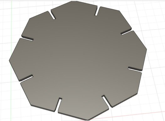
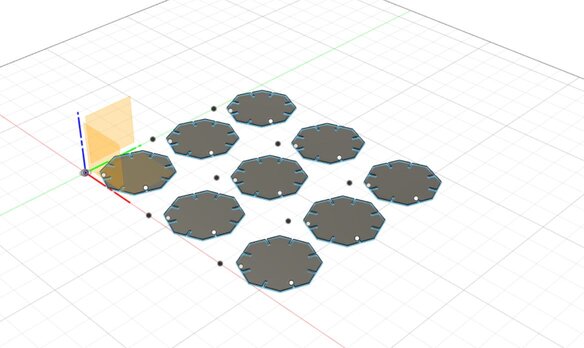
After that I extrude the piece to check its model.
As a curiosity, these are all NOT configured parameters.
Finally I cloned the piece which are linked so they can changed if you change 1 user parameter in "Parameter" window.
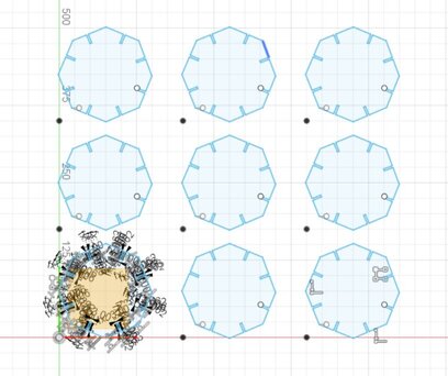
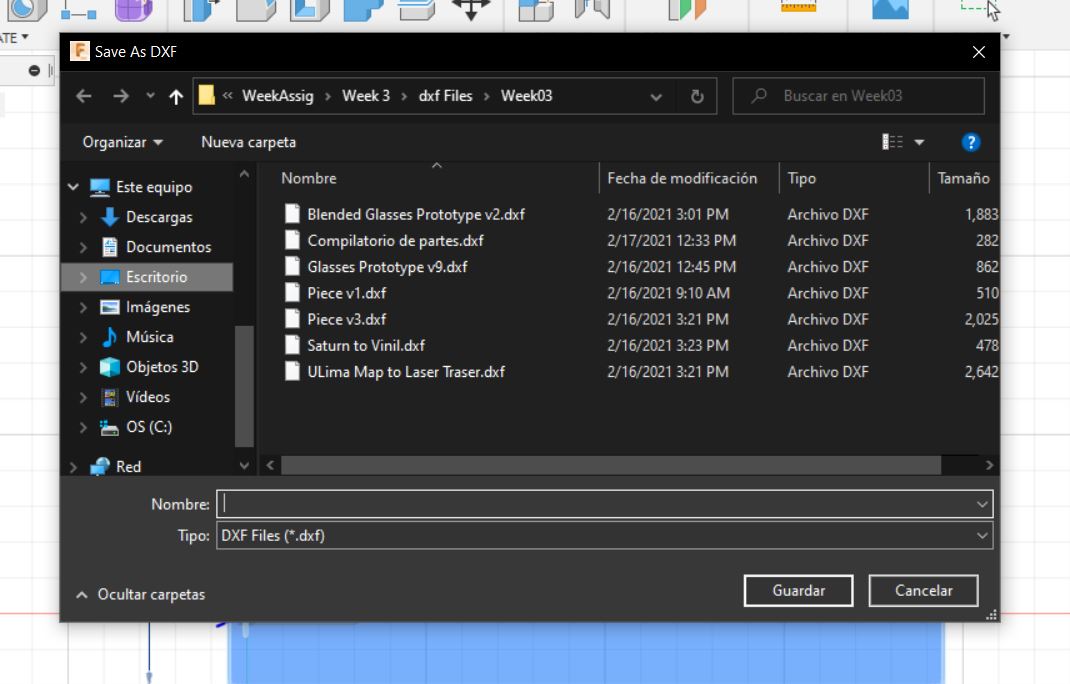
I export this file as .dxf format to make possible for this machine's software recognize it but thare was another propblem. Epilog's software didn't recognize my scale as you can see in the next image.
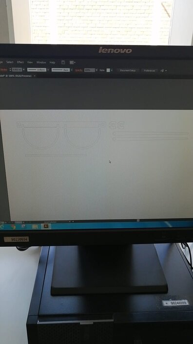
Researching for some information, I could find a helpful post in Autodesk's FAQ and following the next instruction, and crossing my finger, was possible to export an optimal file format .dxf for this software.
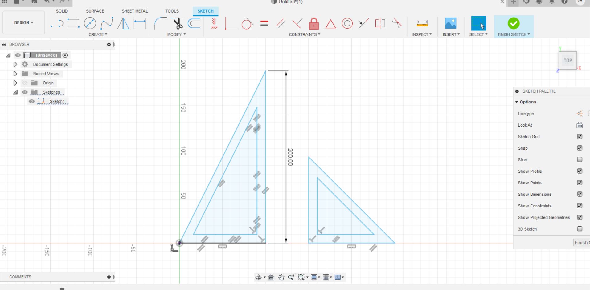
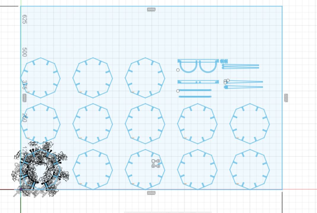
1. We have to go to our sketch. If you have some sketches, it's recommended to group to reduce material's waste. It will be helpful to build a rectangule with maximun dimension of the machine's action surface and leaving some space between the product and every side.
2. Go to this part and right click over the "Sketch" icon you want to save.
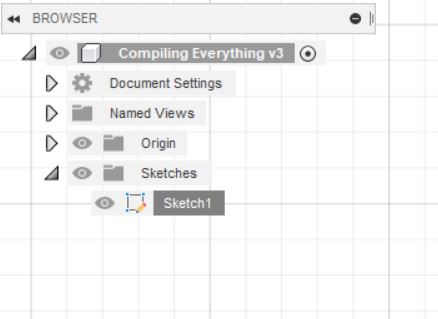
3. You will find some option and you have to choose export as ".dxf" file, this option just save the vectorized sketch.
AFter I solved this problem, I download and integrated my file in Epilog software, in the software are some predefined profiles called: Raster to print on surface, and Vector to cut the material. Based on that and taking care about the relation between speed and power, and the tolerance,
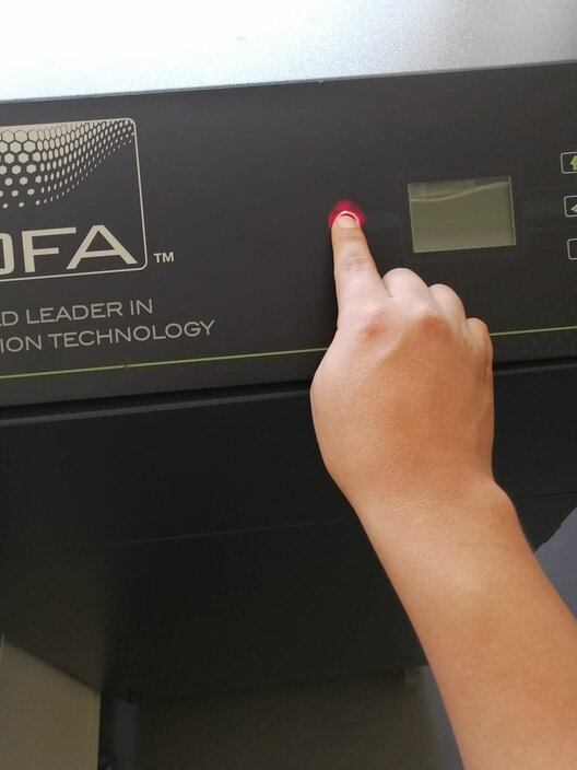
Before I started the process I had to turn on the Air and Smoker Extractor.
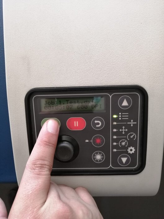
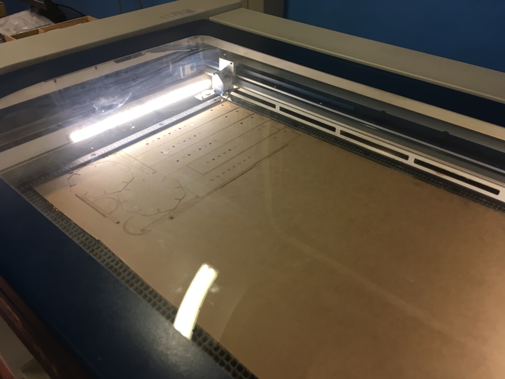
Then I could start the process pressing the green button. As you can see my file called "Test1.dxf" is loaded in Epilog machine.
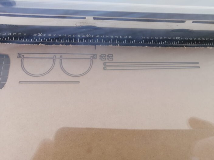
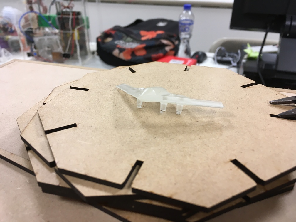
Then a problem happened, I forgot to calibrate Z-Axis so I got a really good printed glasses' pieces.
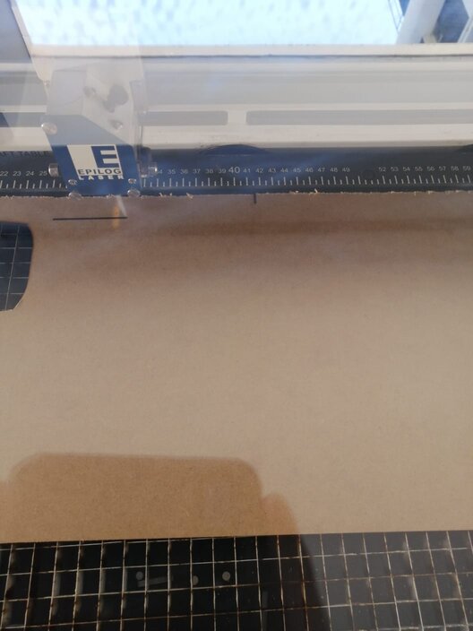
After that I'd calibrated this part the process finally started.
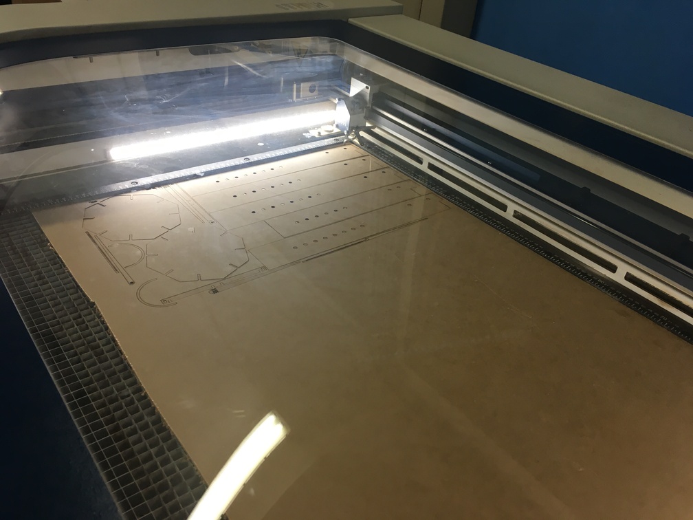
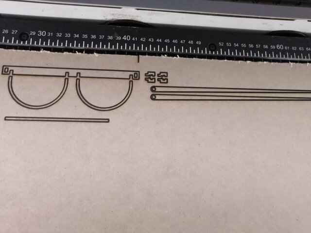
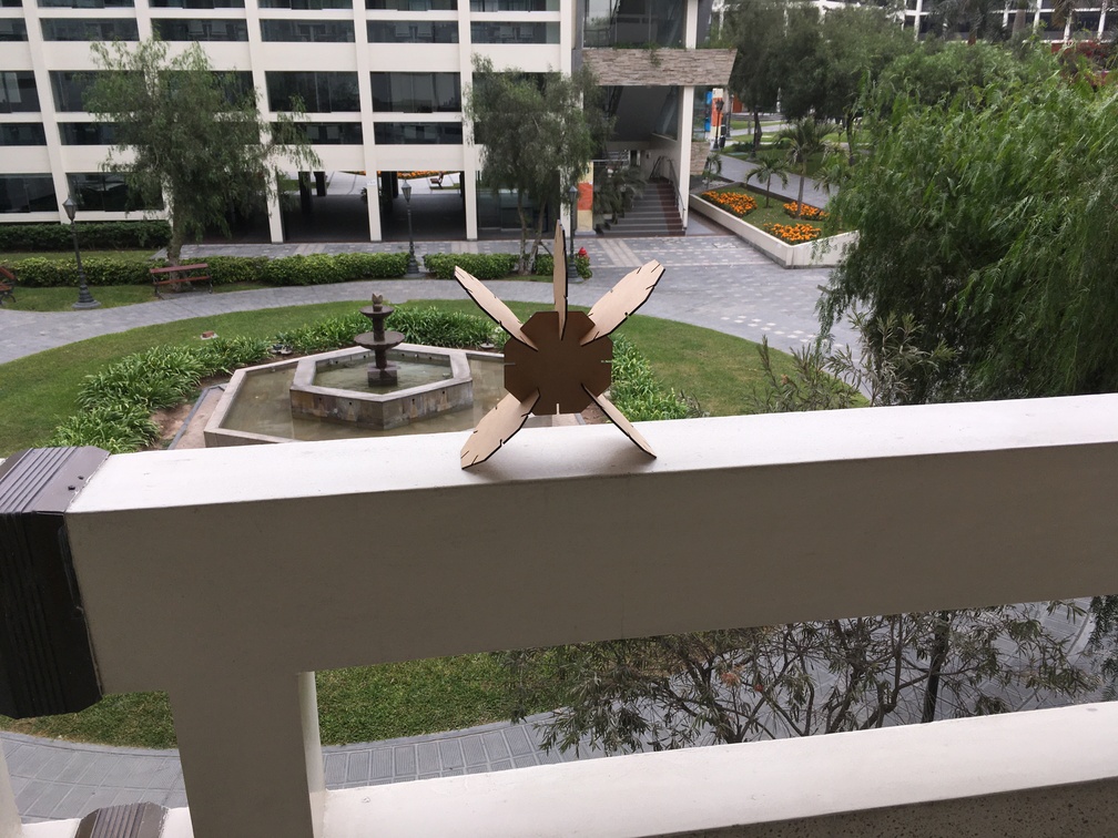
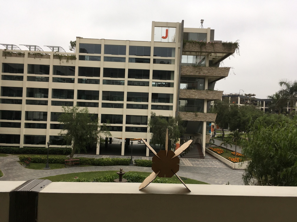
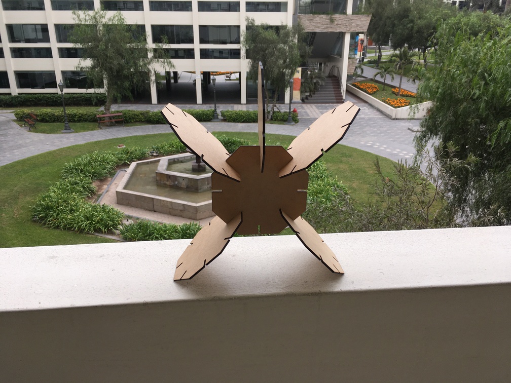
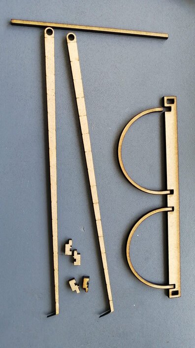
Note: In this operation I cut the MDF sheets for a test for my final project.
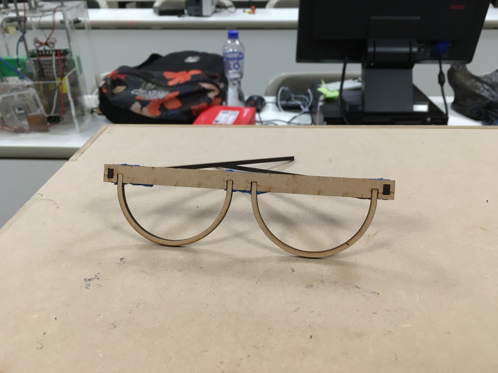
Here are my final pieces.
Another way to get a beautiful glasses...!!!
To this part I had lots of ideas to useful or not so useful thing. I chose to create a pair of folded glasses. But before that I decide to practice the tolerance of pieces so I first designed these glasses with a machanical hinge based on some of my childhood experience with some chinese pirate Lego.
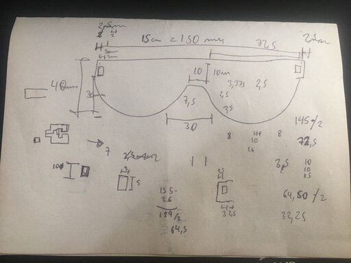
1st I sketched my project and took some measurements based on my real glasses. And I designed my own kind of hinges.
Let's take a look of the total of parameters it has, a bunch of no predefined parameters. Don't worry, I predefined my own parameters before I started the design.
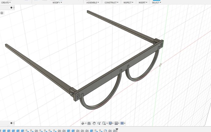
Here is the final sketch designed in a 3D view.
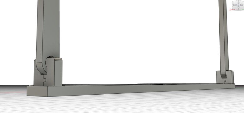
As a curiosity, take a look of its hinges I designed those based on my childhood experience.
I cut it with same protocols as the last parametric piece, and then I assembled to finally got this.
Here is a video how to assembly the hinges.
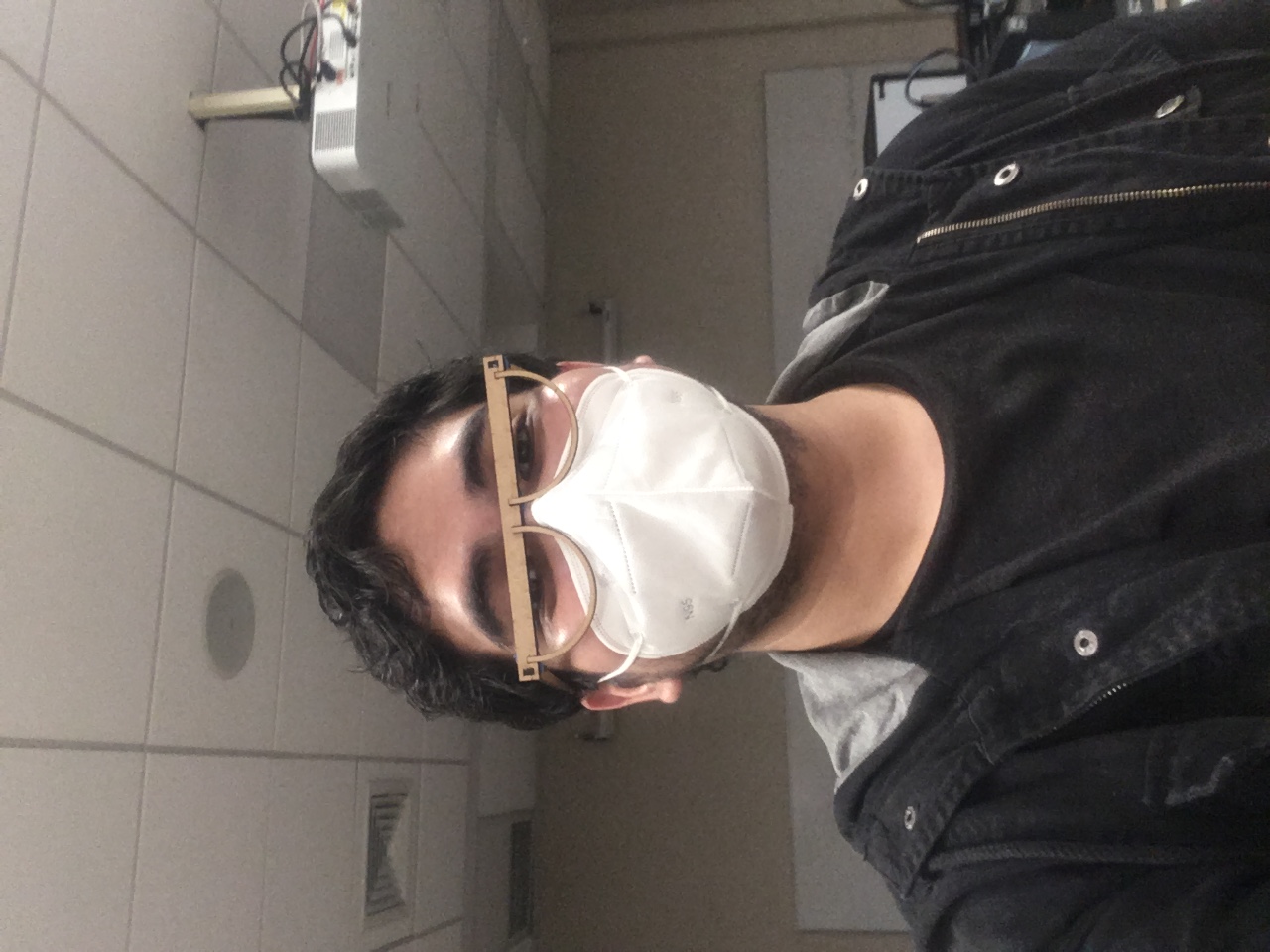
Having assembly all you will have this
Here I am waring these glasses
Let me tell you what problems I had
1st and more important: I started this course in February of 2021 and in my country, where I was coursing the program, we got some restrictions due to pandemic situation which make impossible for me to go to my node lab to progress as usually it is. Beside of that, my node instructor, Alejandro, gave me support and solutions for this situation. I took some notes which helped me to fill some information about the machines I used to develop this assignment.
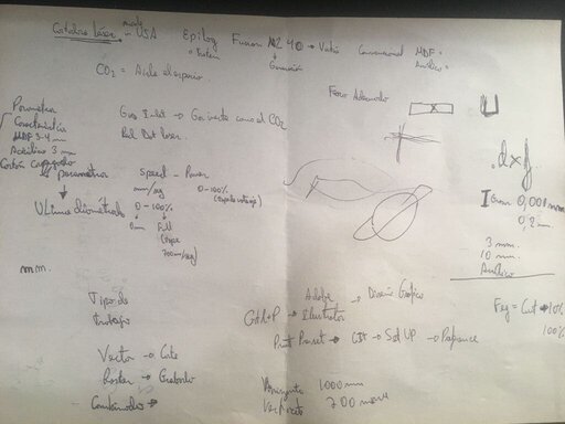
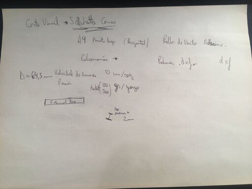
Note: I know this are modern times but really love writing and drawing by hand, and it's de-stressing for me.
Note 2: I am sorry if you cannot read or understand what I wrote. For the first, my handwriting is not as well as I want or expect. And for 2nd one, I am native of a Spanish country (Peru) and at time I was taking note I didn't realize I was doing it in Spanish.
2nd machines' softwares didn't read the .dxf format so was impossible to print or cut. To solve this we have to opened in licensed software like AutoCad to export in a especific .dxf format. I explained this solution on "Laser cutting " but I will save your time Autodesk's FAQ
Files
Below you will find my files which I made this week.