Final Project
I love making robots specially when they will be used to learn about robotics, programming and electronics. Nevertheless, I realized that there are no low-cost kits to create multiple robots with servomotors and motors. Most of the time, we must design the whole robot because the accessories to hold a motor or a servomotors are not easily attachable. Therefore, my idea is to create a special holder for servomotors and motors to put many actuators together and build multiple robots. The holder will be design in a way that can be fabricated with no troubles and most importantly that has a special attachment to be a clip and play robot.
The general idea of the holders and some of the robots that can be made is shown below:
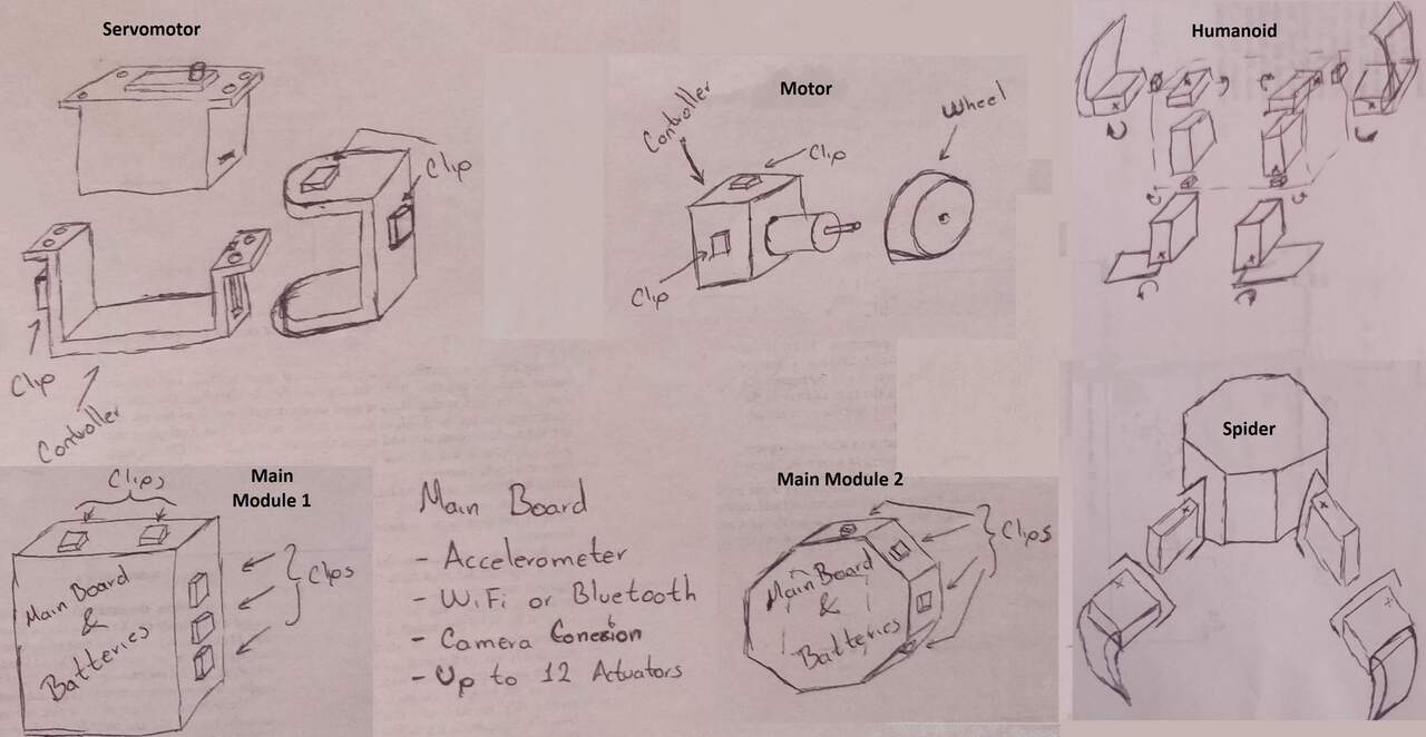
As can be seen in the previous image. With the special holder for the servomotor and motor you can create multiple bodies or robots. I want to try to have an individual controller in each holder so I can controller every actuator with the main controller via I2C. However, it might be easier for send the required wires to the main controller. Another idea for the main controller is to have Wi-Fi and/or Bluetooth connection to create an app and manipulate the robot via wireless. Also the controller must have an accelerometer in case the person build an humanoid, it can detect when it falls. Finally, I am analyzing the possibility to have a camera connector in the main board to attache a camera in case that the robot needs it.
Designing the first version of my robot
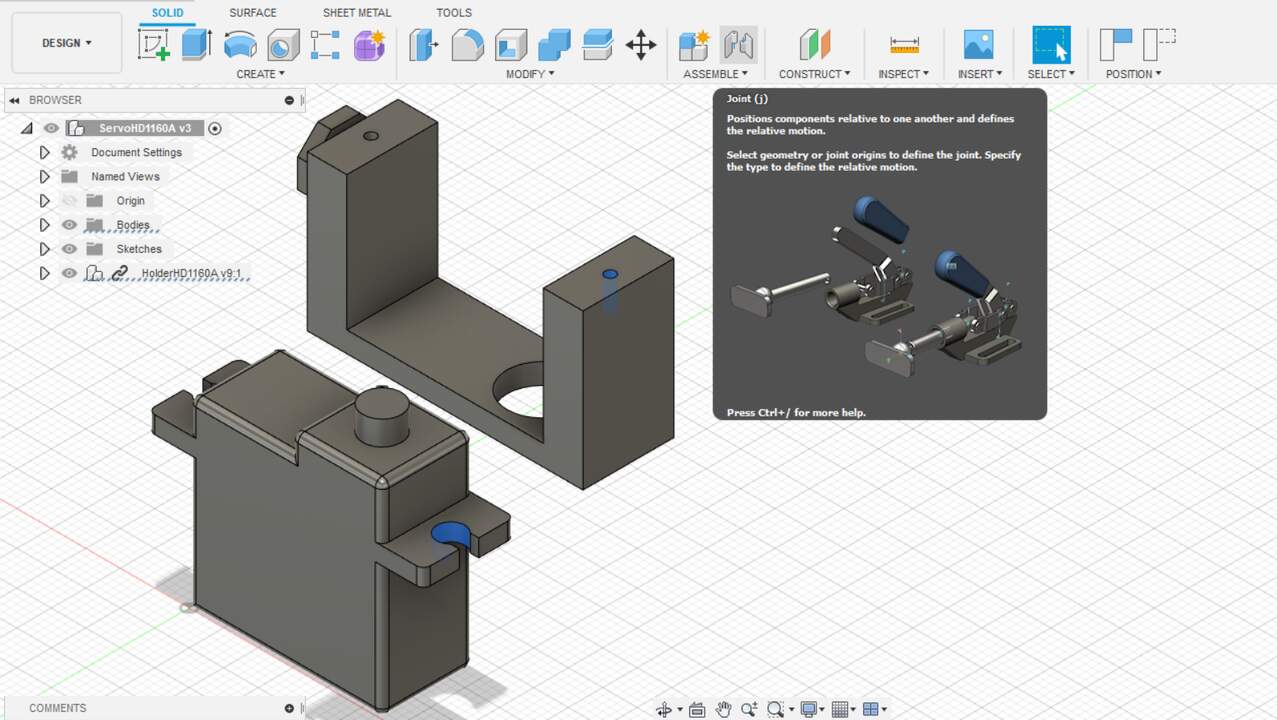
I started the design of my project when practicing but I just drew a few components of a final product. Thus, I used Fusion 360 as my main CAD software and I designed componenet by component. The first robot that I design was a spider with 6 legs and each legs has two servomotors. Since I already had the servomotors, I began with the servomotor holder and the c-profile that moves according to the servomotor movement. These two designs are presented below.
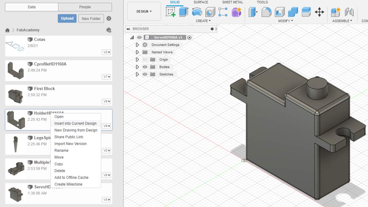
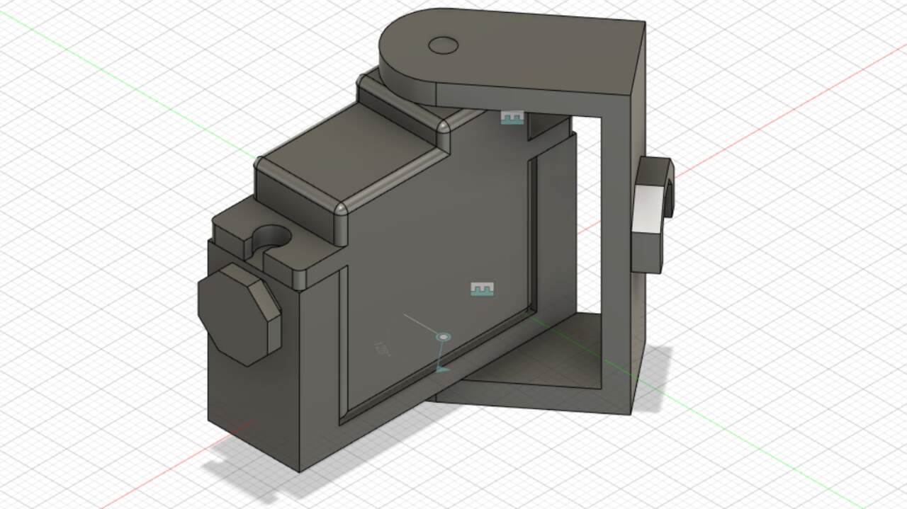
Once I finished with the two main components, I started the assembling process of the spider. I first put togheter the servomotor, the holder of the servomotor and the c-profile. To do this assembly I opened the servomotor file and I click on the top-left icon that looks like a square to see all the files that I had on the cloud. Afterwards, I searched the file that I wanted and I did a left-click over this file. A menu pop-up, and I chose the option "Insert into Current Design" and the design was brought into the servomotor file. Succeding the addition of the other part, I selected two surfaces that I wanted to joint in order to build constraints between components.
I kept adding the c-profile component and the required joint to simulate the servomotor movement and so I could get the first unit which is composed of one servomotor, one holder and one c-profile. Next, I added two units that use the servomotor holder of one unit and the c-profile of the other unit.
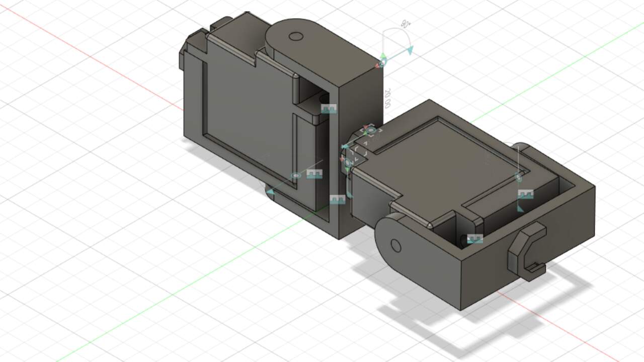
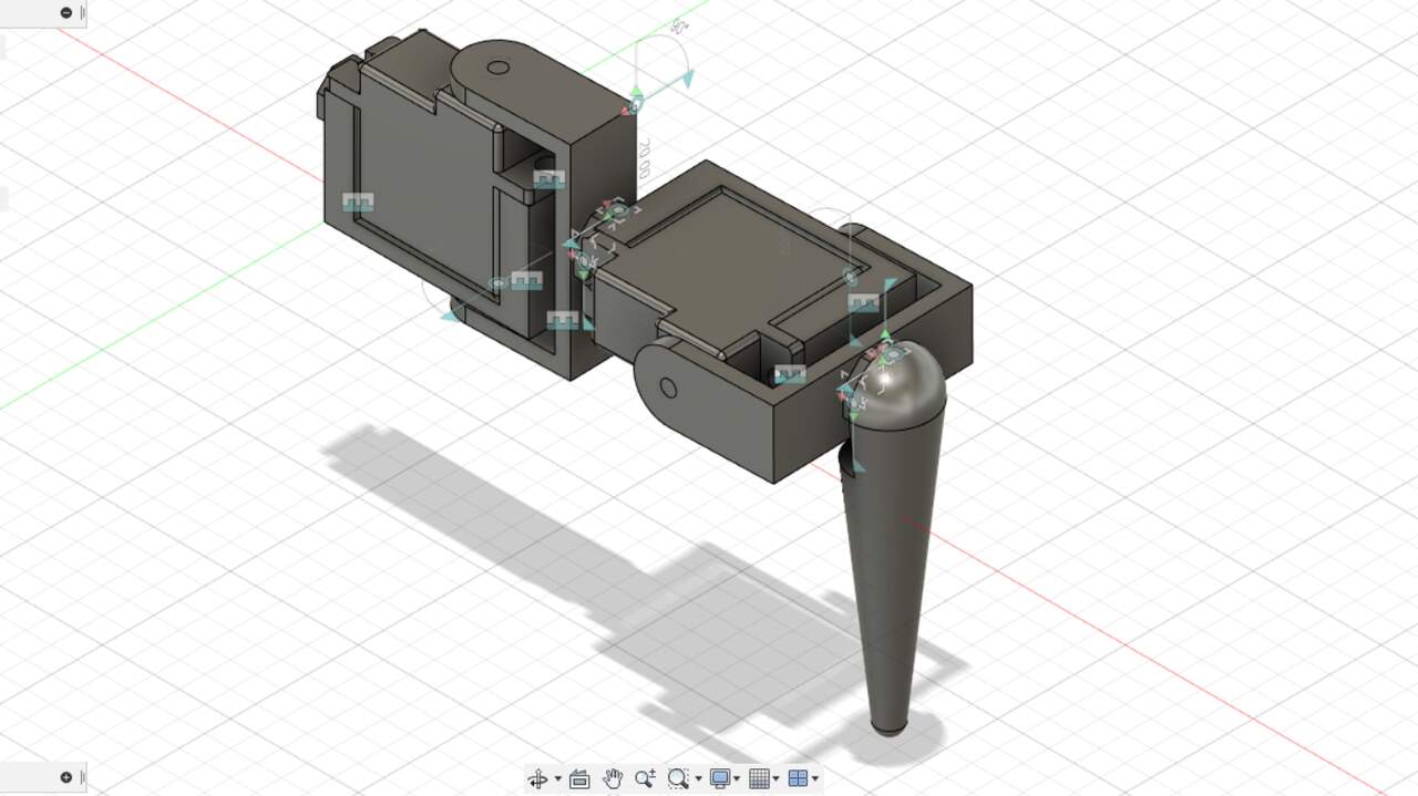
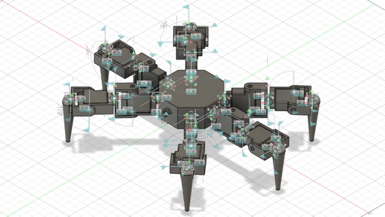
I used the design with two units and I added a leg to simulate the whole spider foot. Finally, I created a new component that holds all the feet of a spider and put togheter six feet to simulate a spider-like robot.
Rendering the robot
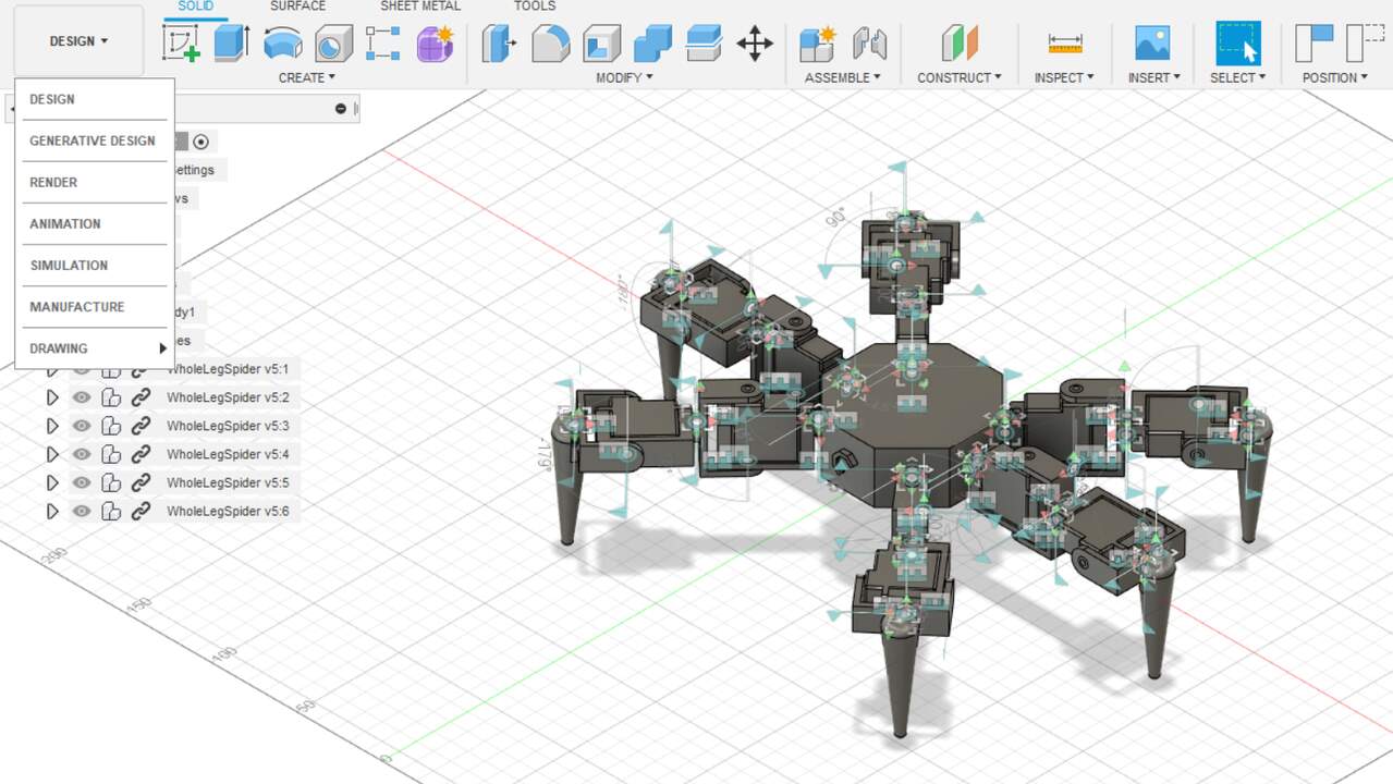
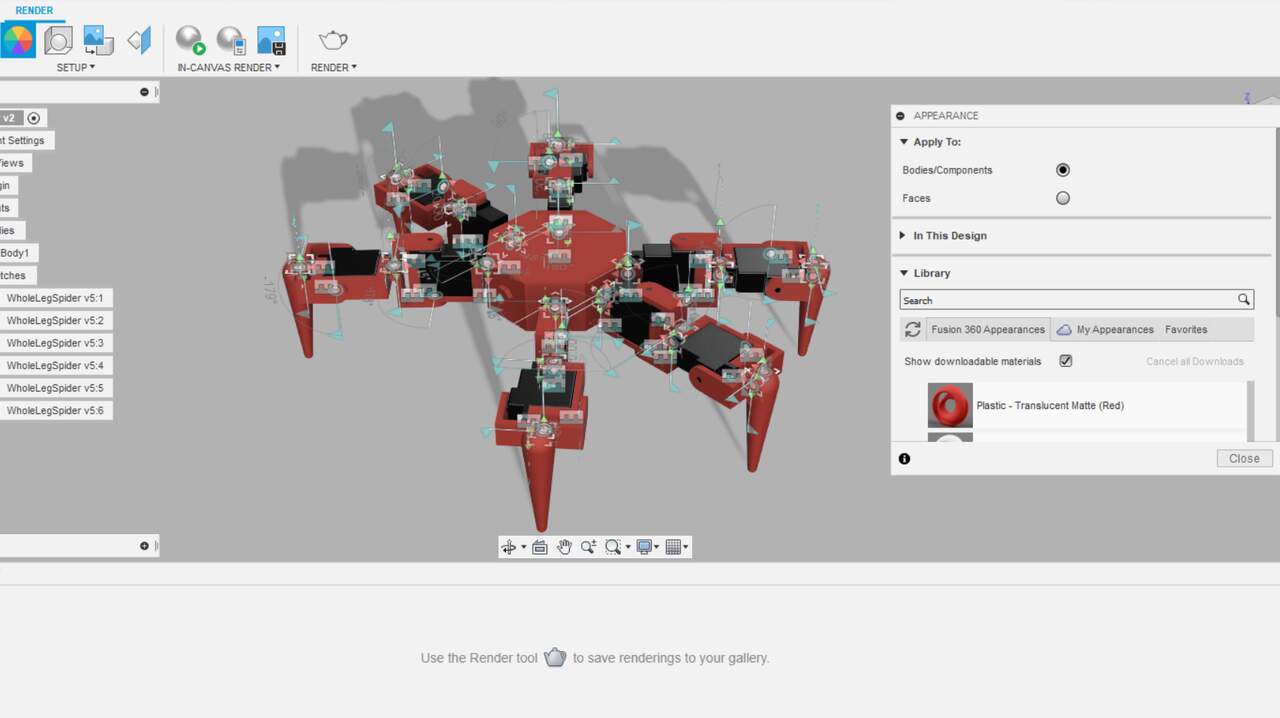
I also used the first version of the robot to produce a render. To start a render, I had to move to the render tab wich is on the top-left corner and can be seen in the images below. After selecting this option, I gave an appearance to each components. I used a black inside plastics for the servomotos and a red also in plastics for the rest of the components. The appearance can be applied from the top menu over the circle with multiple colors. A new tab will be opened and there, you can select the color that you like. To apply the color to a specific component, you must drag the wanted color over the component.
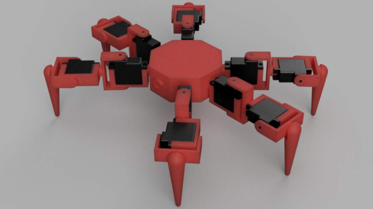
To produce a final render, you just have to click on the sphere with a play symbol and the options about the quality and dimensions will appear. In my case, I used the default setting because I have a educational license but it produce a really good result as can be seen in the image below.
Animation of the robot
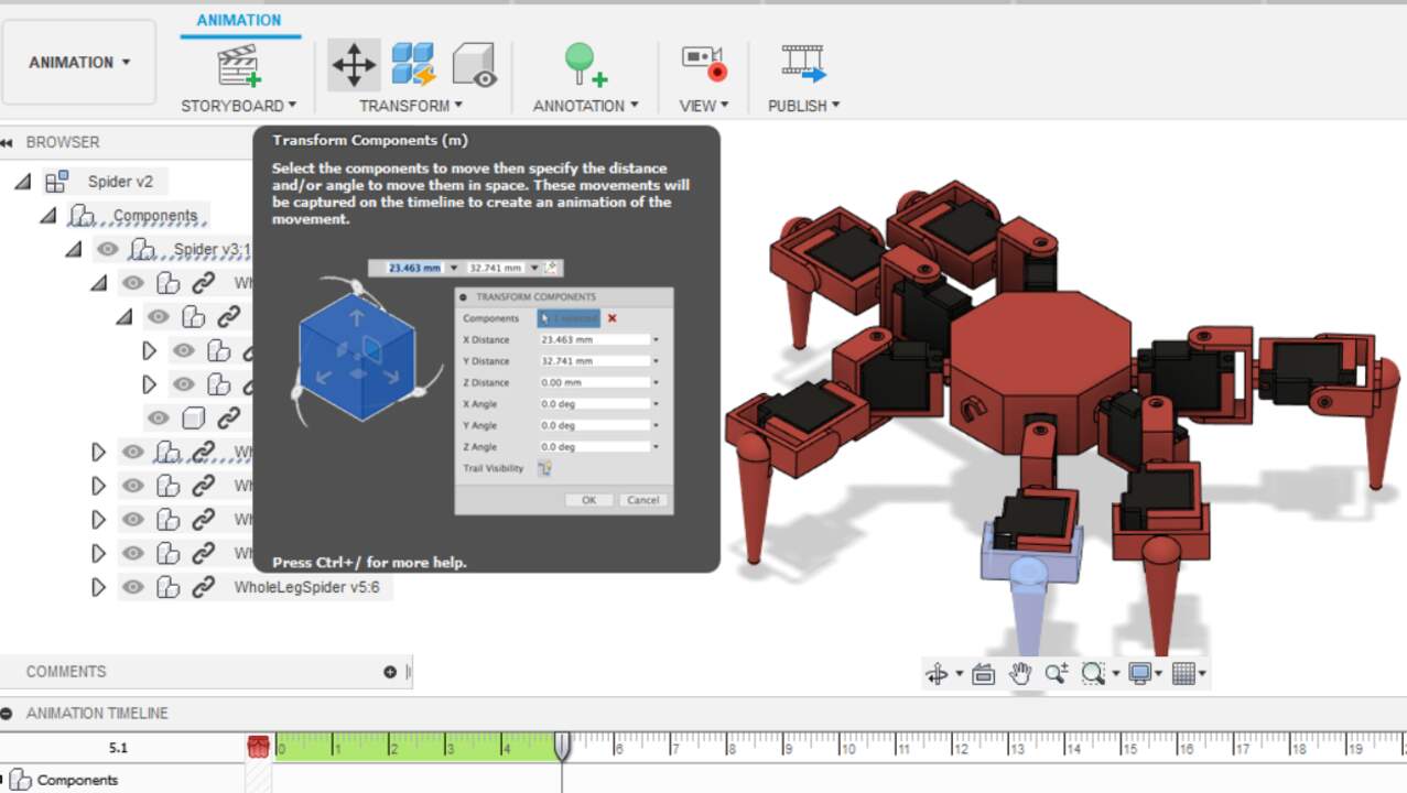
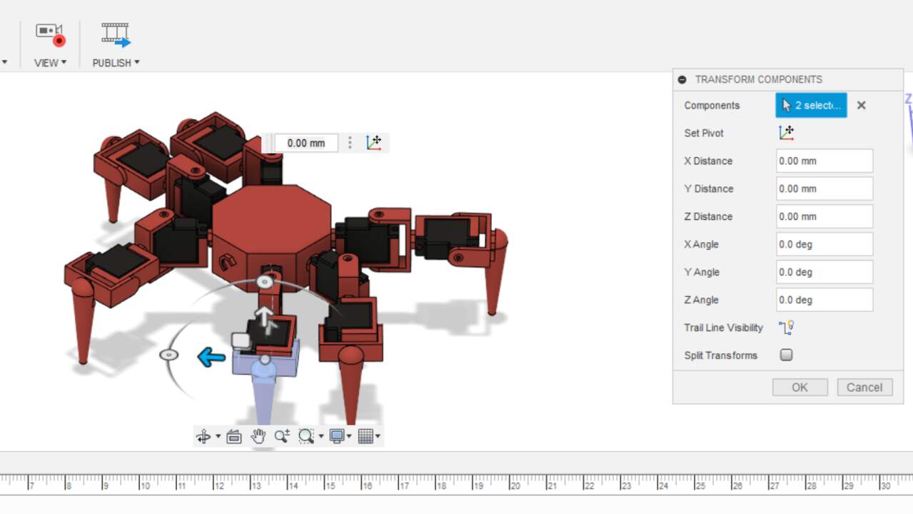
The last function that I used in Fusion 360 with the robot was the animation. The animation is really easy if you understood the joints (constraints) definition in Fusion 360. First, you must move into the animation part in the top-left menu. After you are inside the animation menu, you have to select the individual components that you want to move and choose the transform button which has a cross. If the seleccion was successful, the software will ask you about a pivot point which is the revolute or linear axis where the component will move. You can use the menu in the right to specify the required movement or you can also use the arrows over the components to move them manually. Once you like the movement, click "OK" and keep setting the next movement you want to register.
To record a video in Fusion 360, you have to click over the "Publish" button on the top menu and it will ask you the settings for the video. As well as the render, I used the default settings to create the video. Finally, a small video of the robot motion is shown below.
Finding the best clip and play system
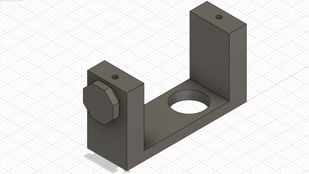
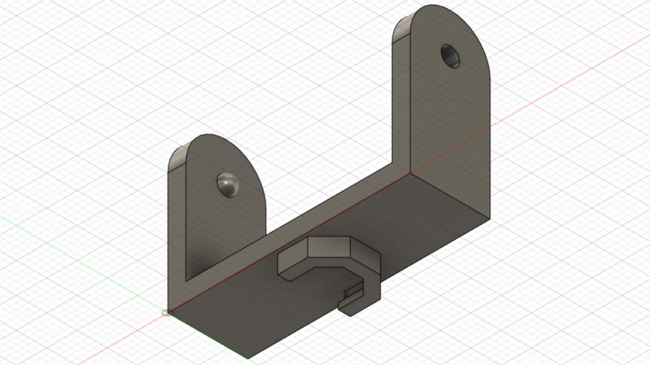
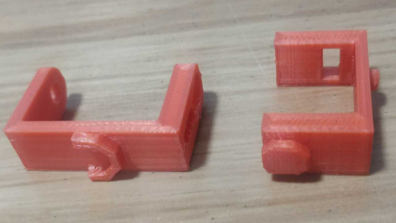
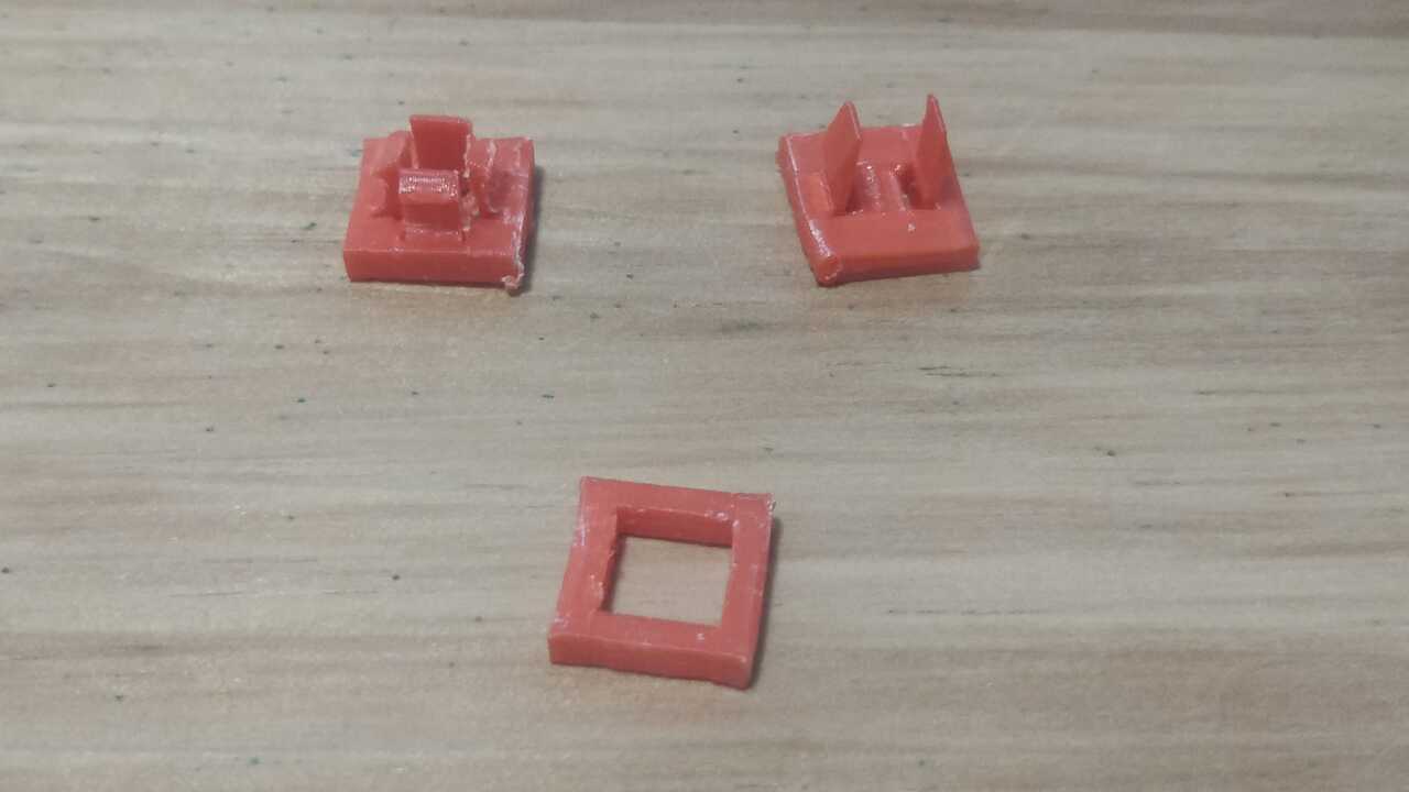
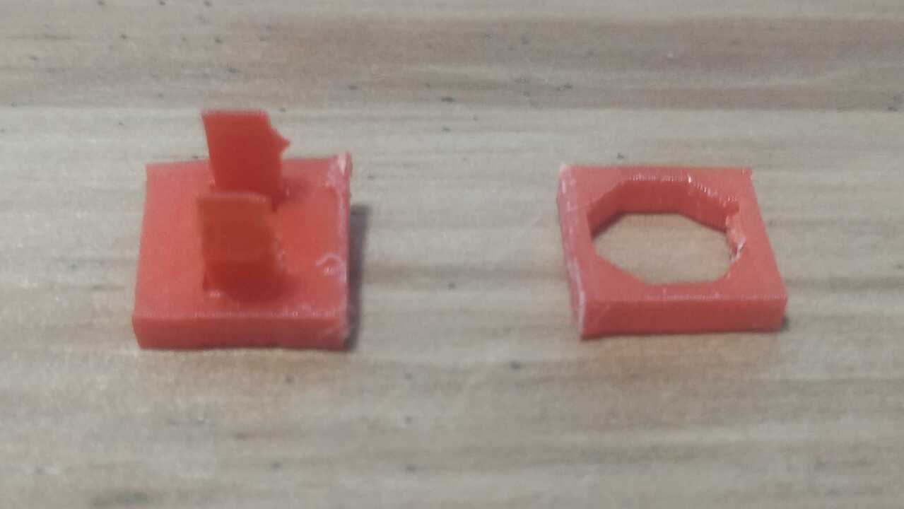
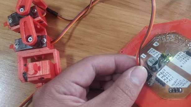
In order to create the first version of my robot, I 3D printed the drawn version that I created in Fusion 360 and that was presented previously on this page. Nevertheless, I realized that the joint was not strong enough to hold both parts and sometimes the female joint broke because it was to thin or the 3D printing was not so precise. Therefore, I created a second version that is shown on the right, where one parts must slide into the other and after it reached its destination a clip will comeback to the original position.
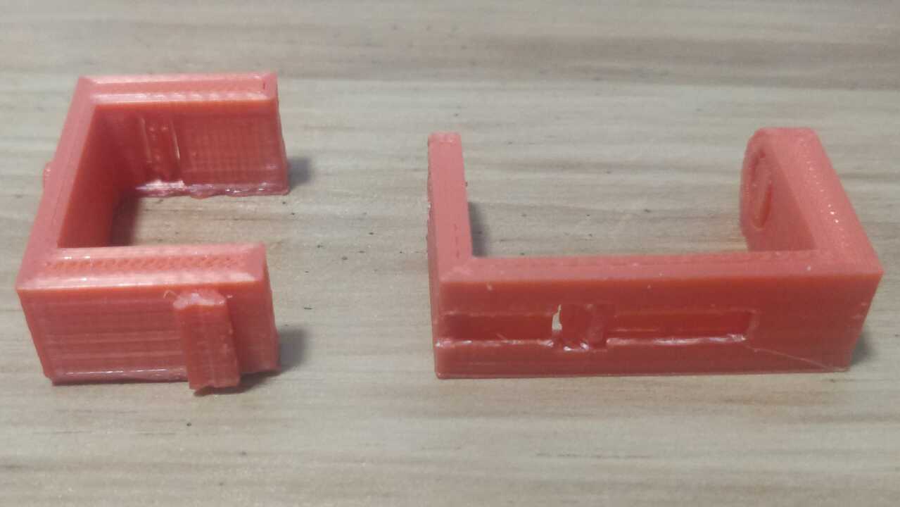
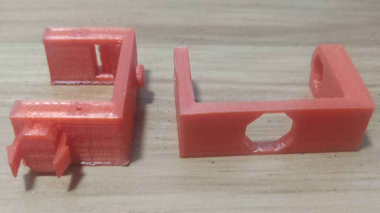
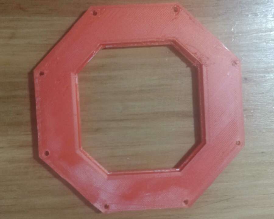
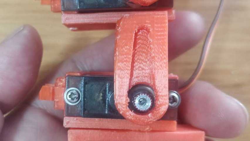
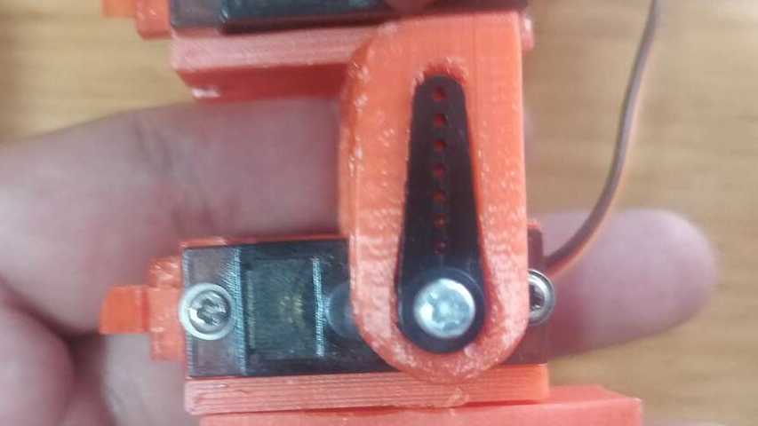
The only problem with the previous version was that I had to create different holder for the servomotors depending on the required assembled angle between servomotor. So, I created another two version that can fit into an square of 10 by 10 mm. Unfortunately, this version was not working as perfect as I wanted because sometimes it is required that you assemble two pieces together in a different angle that 0 or 90. Thus, I created a fourth version that instead of using a square, I used an octagon with a clip and an octagon shape to hold the pieces as much as possible.
When I saw that the fittings was working as I planned, I proceed to create the last version of the servomotor holder and the C-profile that moves with the servomotor shaft. It is important to remeber that any good prototype requires many iterations to achieve the most efficient way or in this chase the most efficient shape.
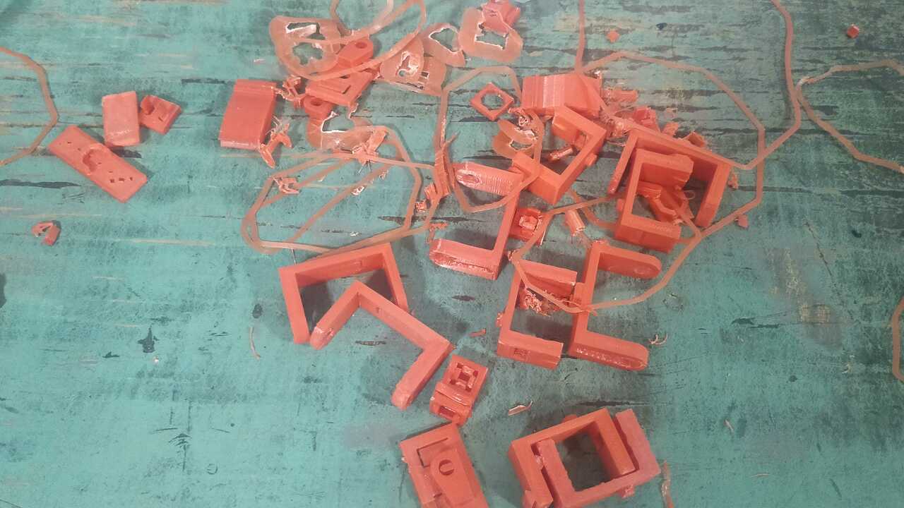
The following video shows the multiple clips that I tested to see what was best for my robot
Fabricating the accesories for the actuators
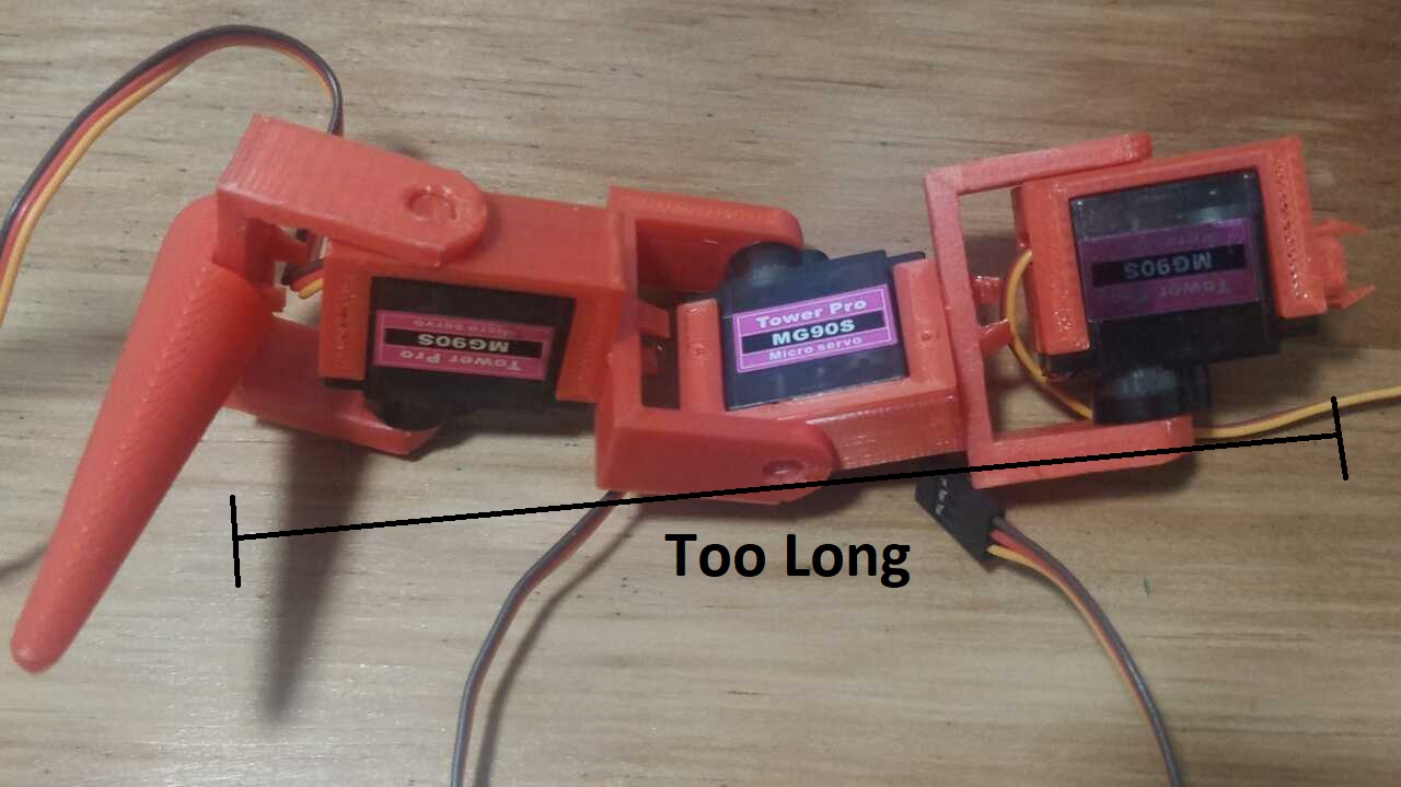
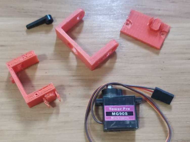
After finding the best clip an play system, I proceed to 3D print a few final holder for the servomotors MG90S and to complete a spider leg but I realized, that the leg was too long and it might cause troubles while moving.
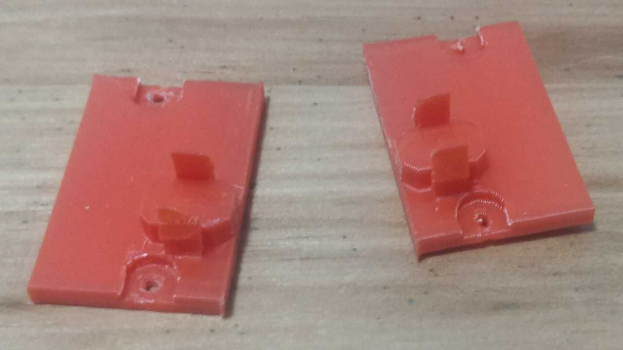
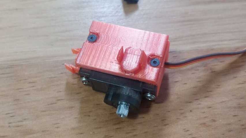
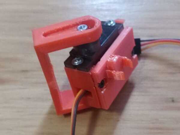
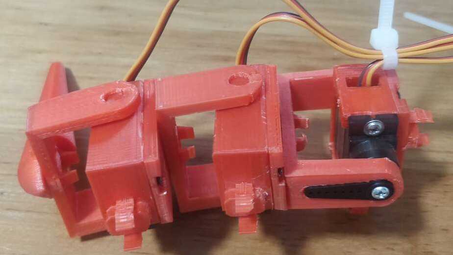
Thus, I decided to create walss with the same clip system to allow the user to place almost in any position and orientation. The idea is to create two parts that goes in one or both sides of the servomotor holder with the clip like the two photos below show.
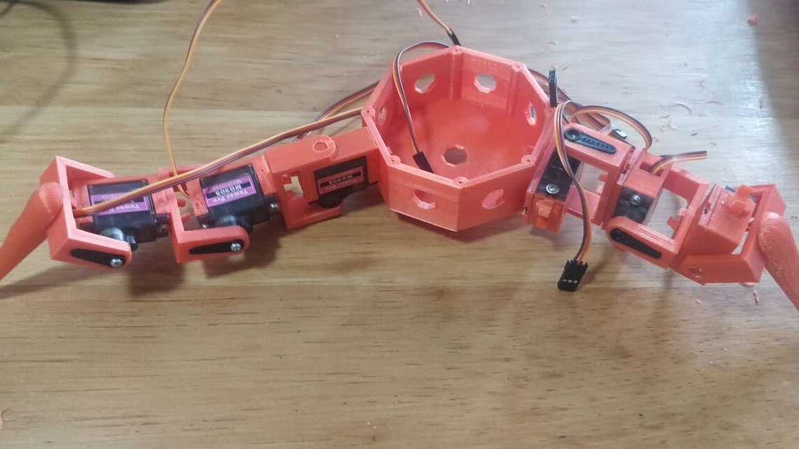
To finish the testing, I create multiple accesories and I put them togheter to form a leg. In the following picture, I show the difference between both legs when they are placed in the main module and it is clear that the shorther leg is more compact and it looks more suitable for the main module.
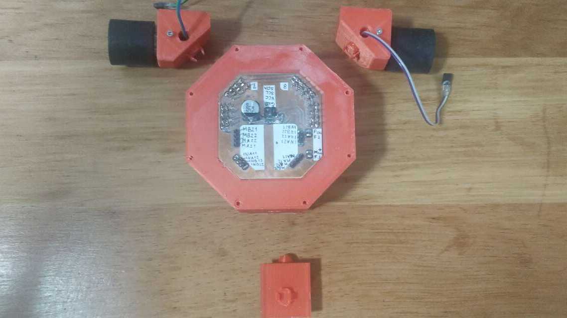
Now using the same clip and play system, I proceed to build the accesories for the COPAL motors 50:1 that I already had from previous robots that I built. Taking in consideration that I the main board is an octagon, I have to create two modules that allow me to have both motor in the same line. Thus, I created both modules with the shape of a triangle to align the motors just like is shown below.
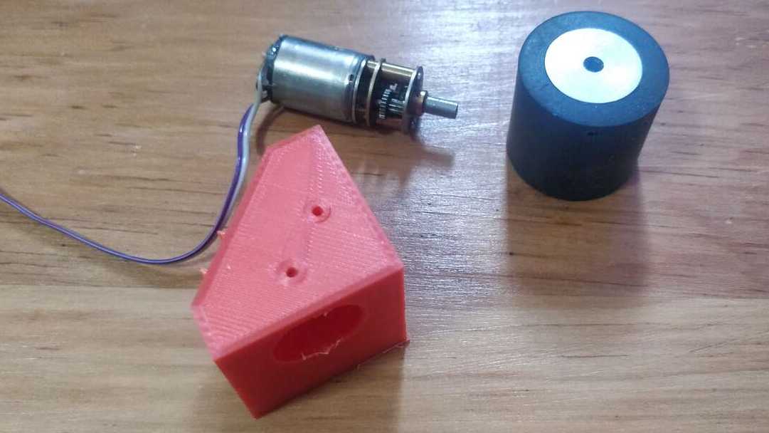
The wheels that was used for these accesories wher bought in hobbycom that is a electronics shop in Mexico City. Nevertheless, when I assembled the pieces together I realized that the bottom part of the piece has a sharp edge and it could avoid that teh robot moves through tilted surfaces.
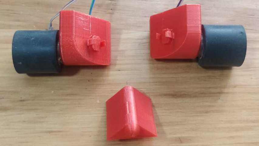
Therefore, I create a second version of the accesories that is fully rounded at the in the face that is pointing towards the floor. And I also reduce the hole where the wires go trough because it was not neccesary to have bigger holes. Finally I also eras one hole for the screws that holds the motors since I only need one of them.
Main circuit for Axolbot
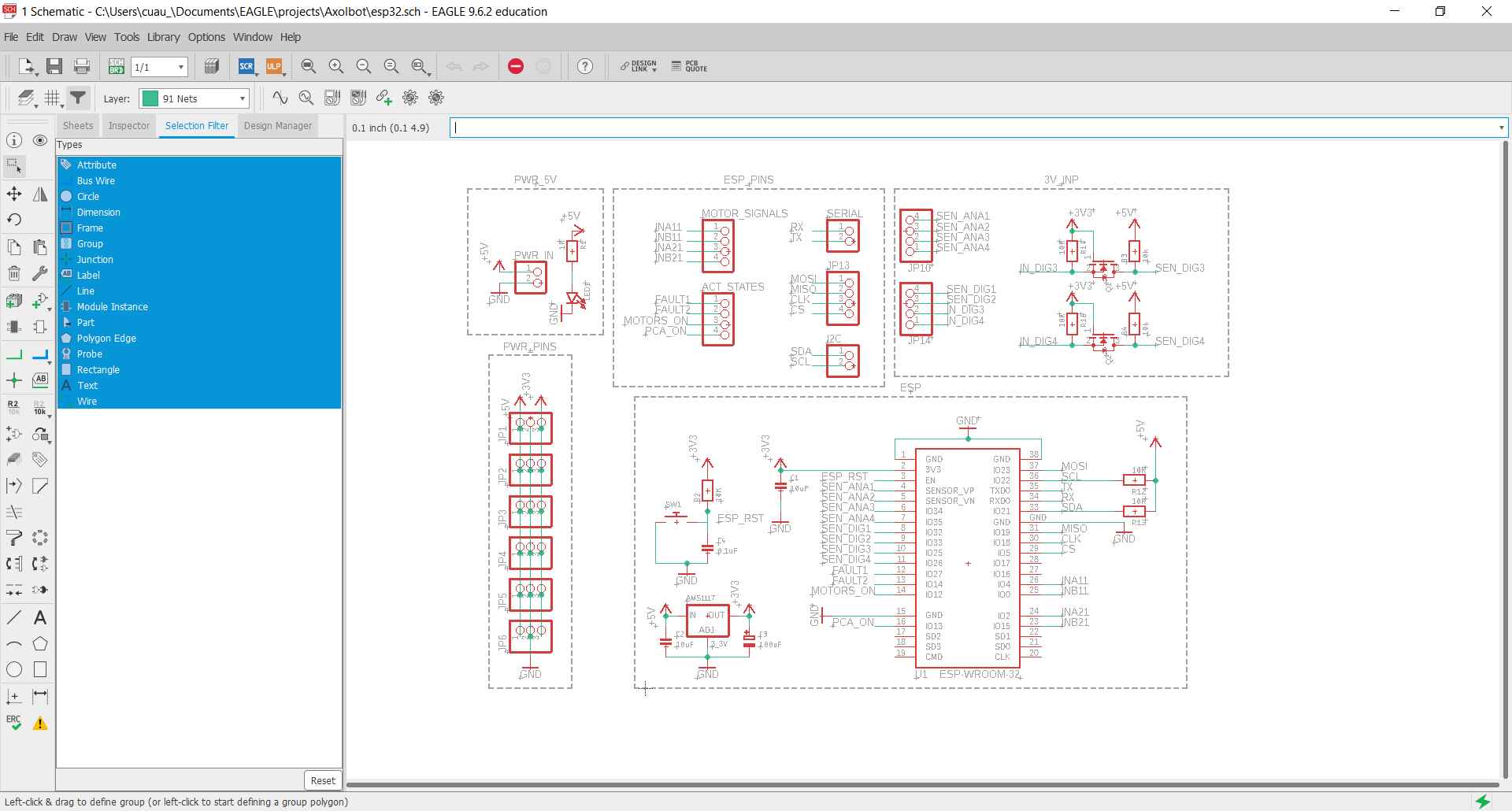
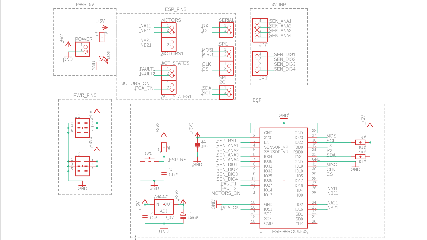
The main board for my robot is powered by an ESP32 because it has WiFi and Bluetooth connectivity which can be really useful to external connection with an application or another device. The board must have pins for I2C, Serial and ISP protocols as well as multiple power pins to provide 3.3 V or 5 V. Thus, I created my first schematics which can be seen below:
With the new schematics, I did the routing manually since I already knew some possible paths that I found in the Electronics Design week. The only problem that I got is that I was not able to have all the paths in the top layer. I tried for many hours there are many paths that make impossible to get all the paths in the top layer. For the 5V path I created two vias to connect both paths as can be seen in the next picture.
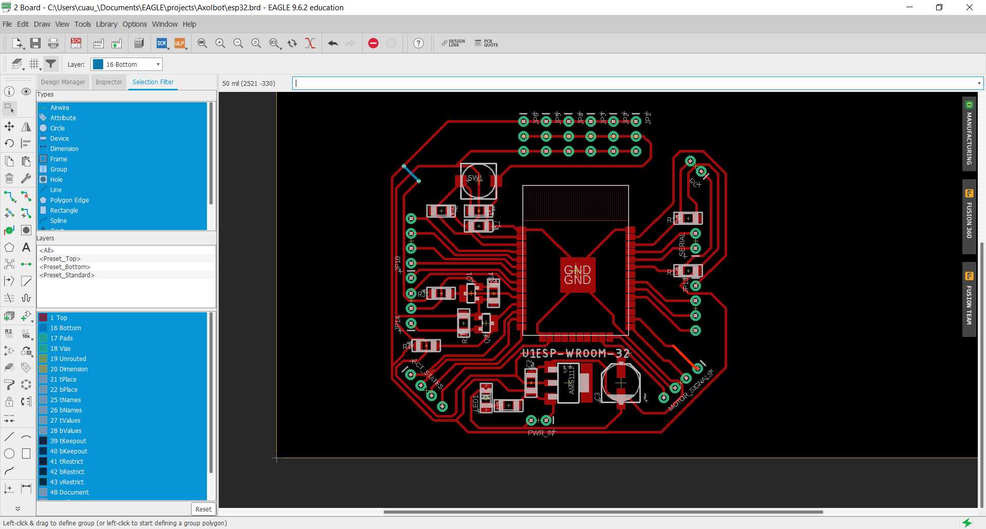
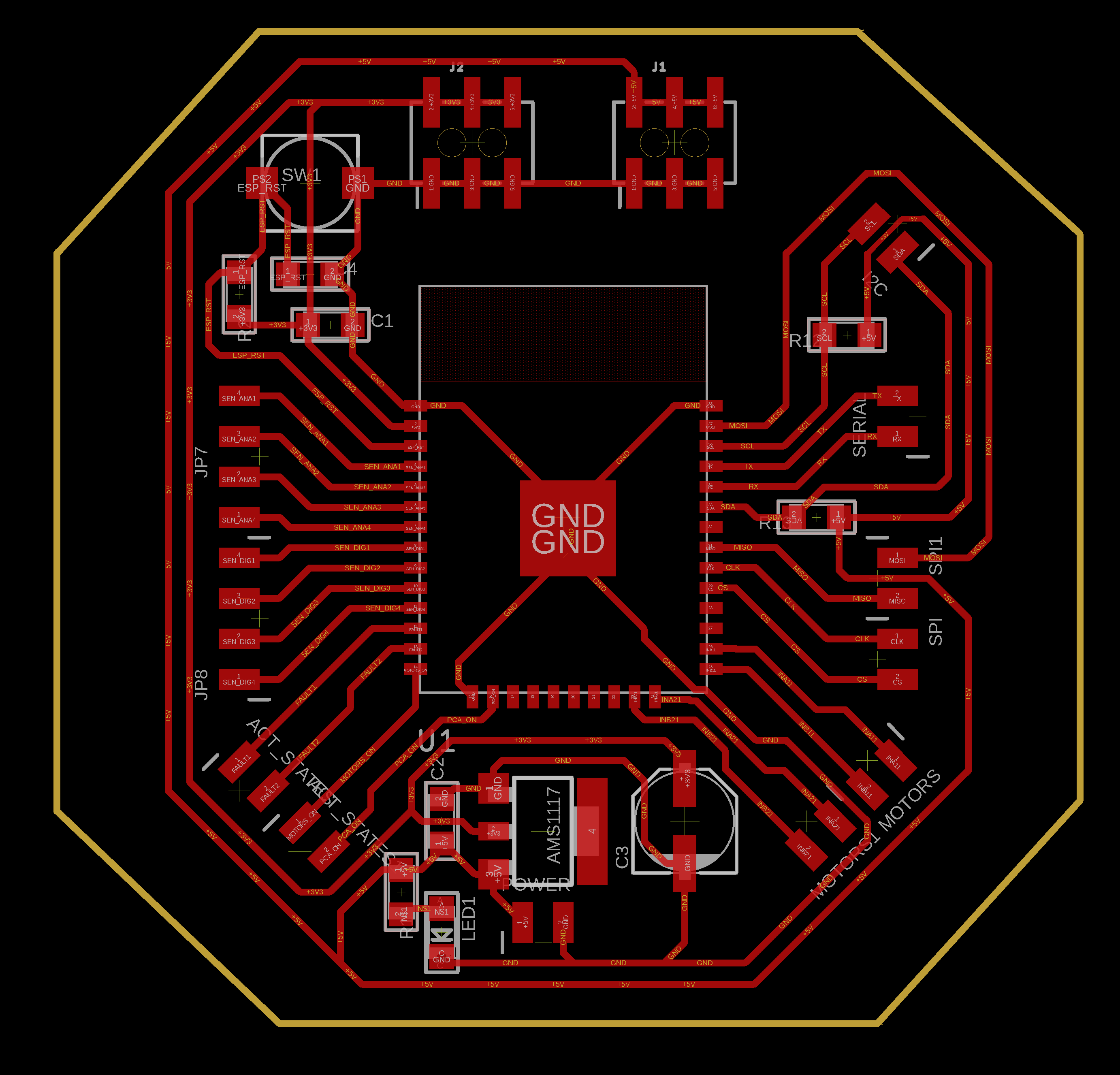
Since I did not have the electronics on time, I had time to rethink my board and look for others options to avoid using a double-sided board since in this version I have through-hole pins and I want to use pins that that can be placed in the top layer. Thus, I decided to see any other options to arrange the components and I found out that the board cannot be created with a single layer without erasing the MOSFETs. Then, I erased those two components because they are only used to change the voltage from 5V to 3.3V or from 3.3V to 5V and they are not really neccesary knowing that the inputs will be restricted to 3.3 V.Thus, the second version of the board is shown below:
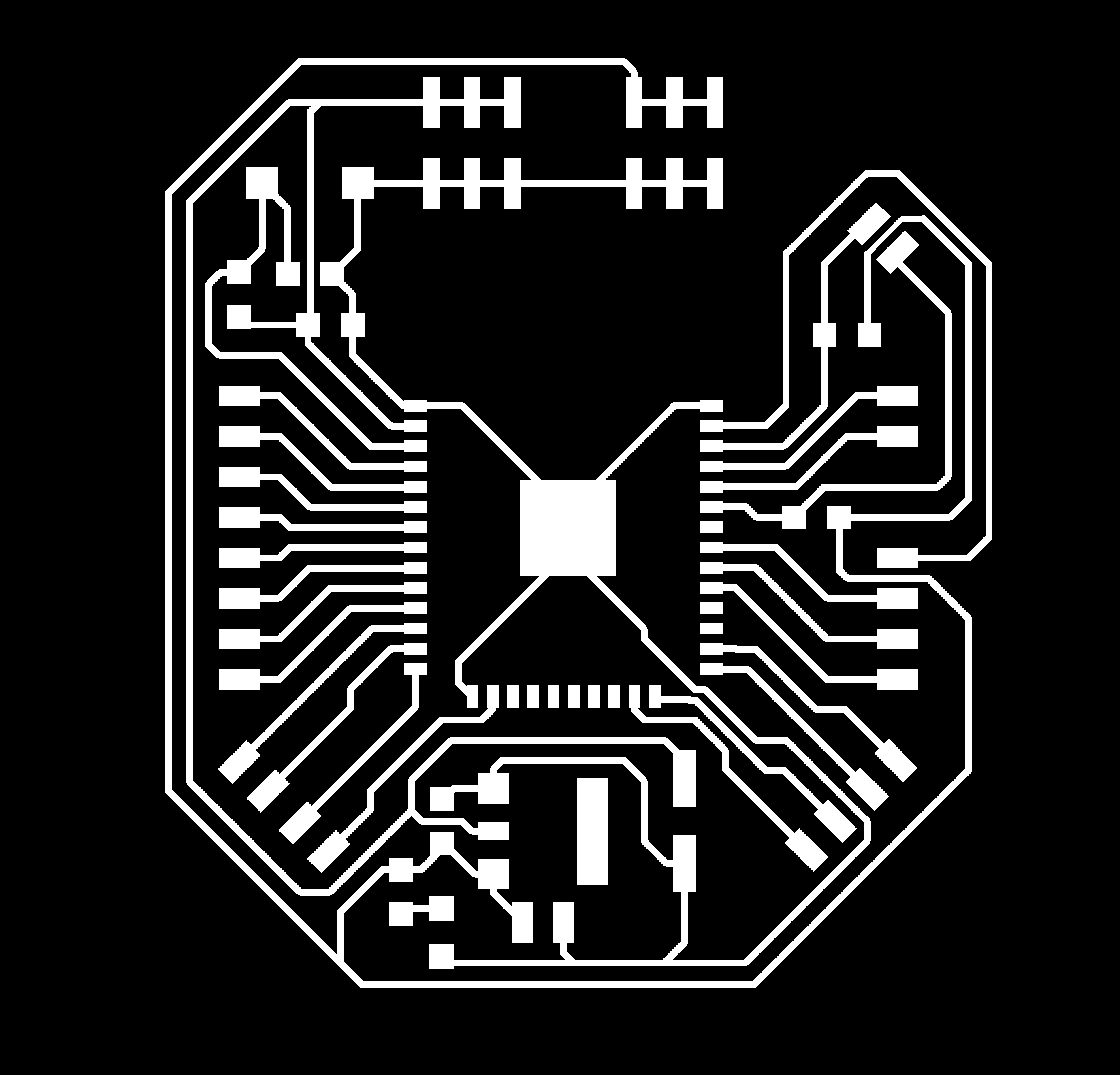
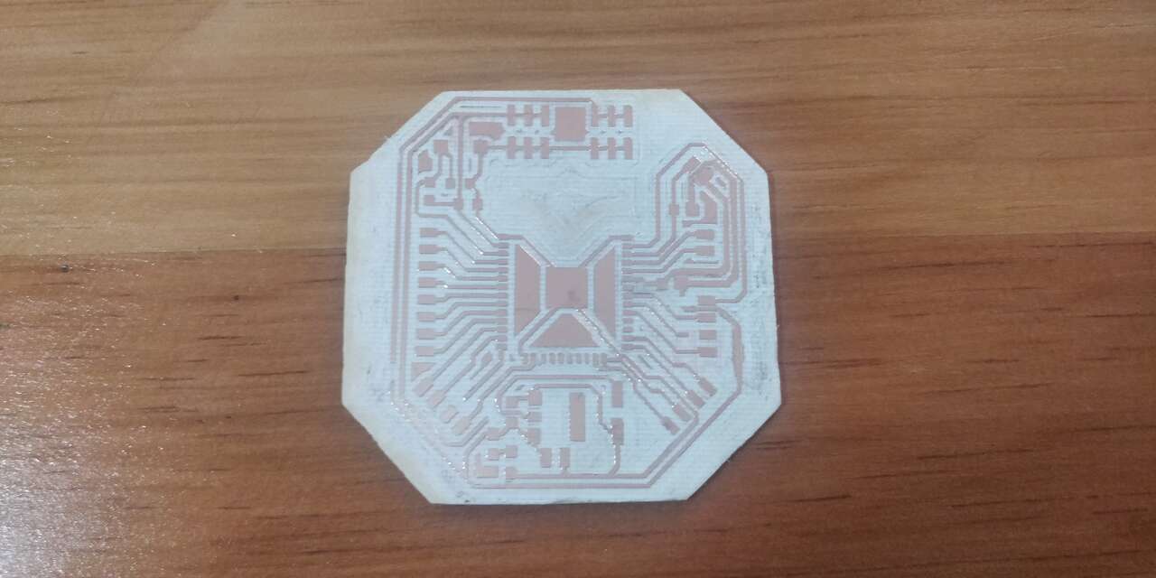
After doing the required changes, I created the new traces and outline files where the most important is that this board is a single layer PCB to ease the fabrication process. The two pictures below show the top layer with the componentes and the traces.
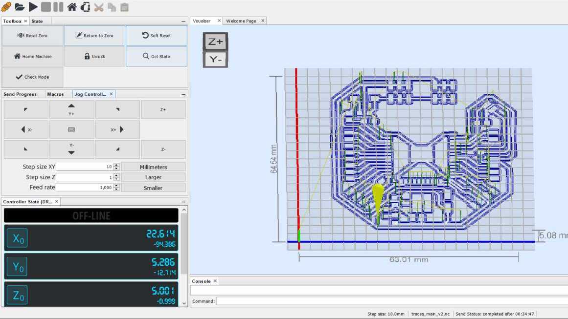
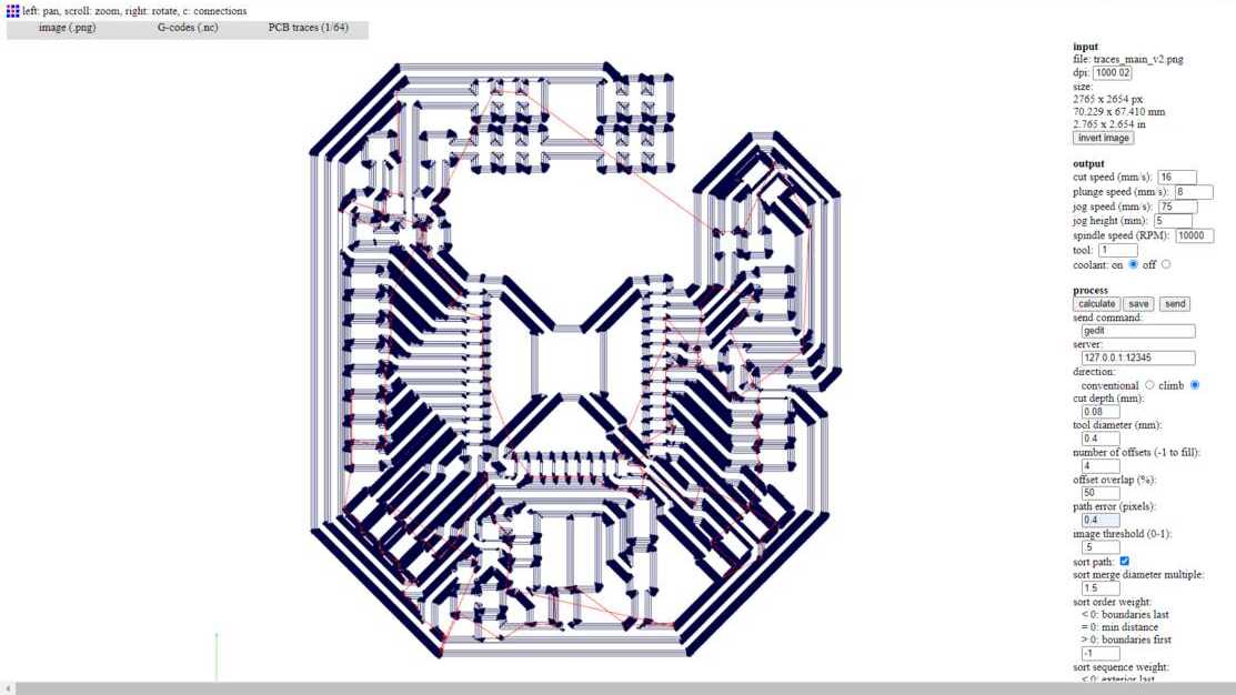
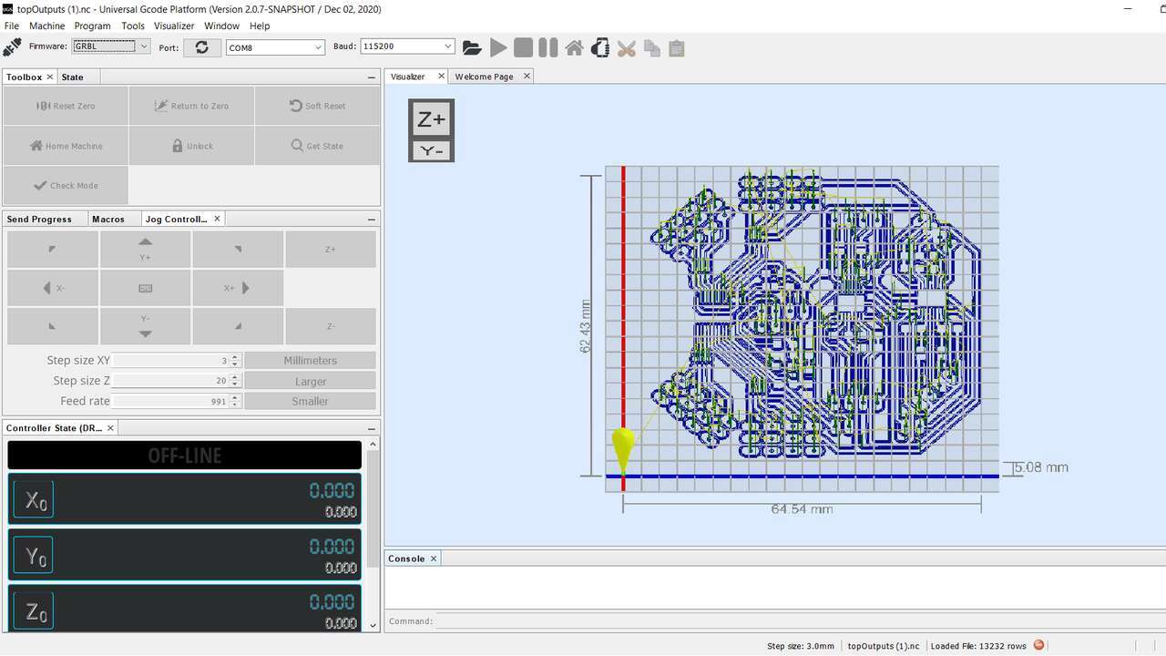
Like the other PCB's, I used fabmodules to generate the G-code and I also used UGS to send the G-code to my Mini Router CNC 3018 PRO.
For the machinning process, I make the same setup as before placing double-sided tape in the board, zeroing the machine, uploading the file, and finally sending the file to create it. It is important to note that the pins that I used are not SMD pins but normal pins that I placed almost horizontal to be able to solder and they worked perfectly.
The following table shows the bill of material to create this PCB.
| Quantity | Component | Model |
|---|---|---|
| 1 | Microcontroller | ESP32-WROOM |
| 1 | 3.3 Regulator | AMS1117 |
| 2 | Ceramic Capacitor | 10uF |
| 1 | Ceramic Capacitor | 0.1uF |
| 1 | Electrolitic Capacitor | 100uF |
| 2 | Mosfet-N | BS138 |
| 1 | Resistor | 1k Ohm |
| 7 | Resistor | 10k Ohm |
| 1 | LED | 1206 |
| 1 | Push Button | SKPMAME010 |
| 3 | Pin header | 1x2 trough hole |
| 6 | Pin header | 1x3 trough hole |
| 4 | Pin header | 1x4 trough hole |
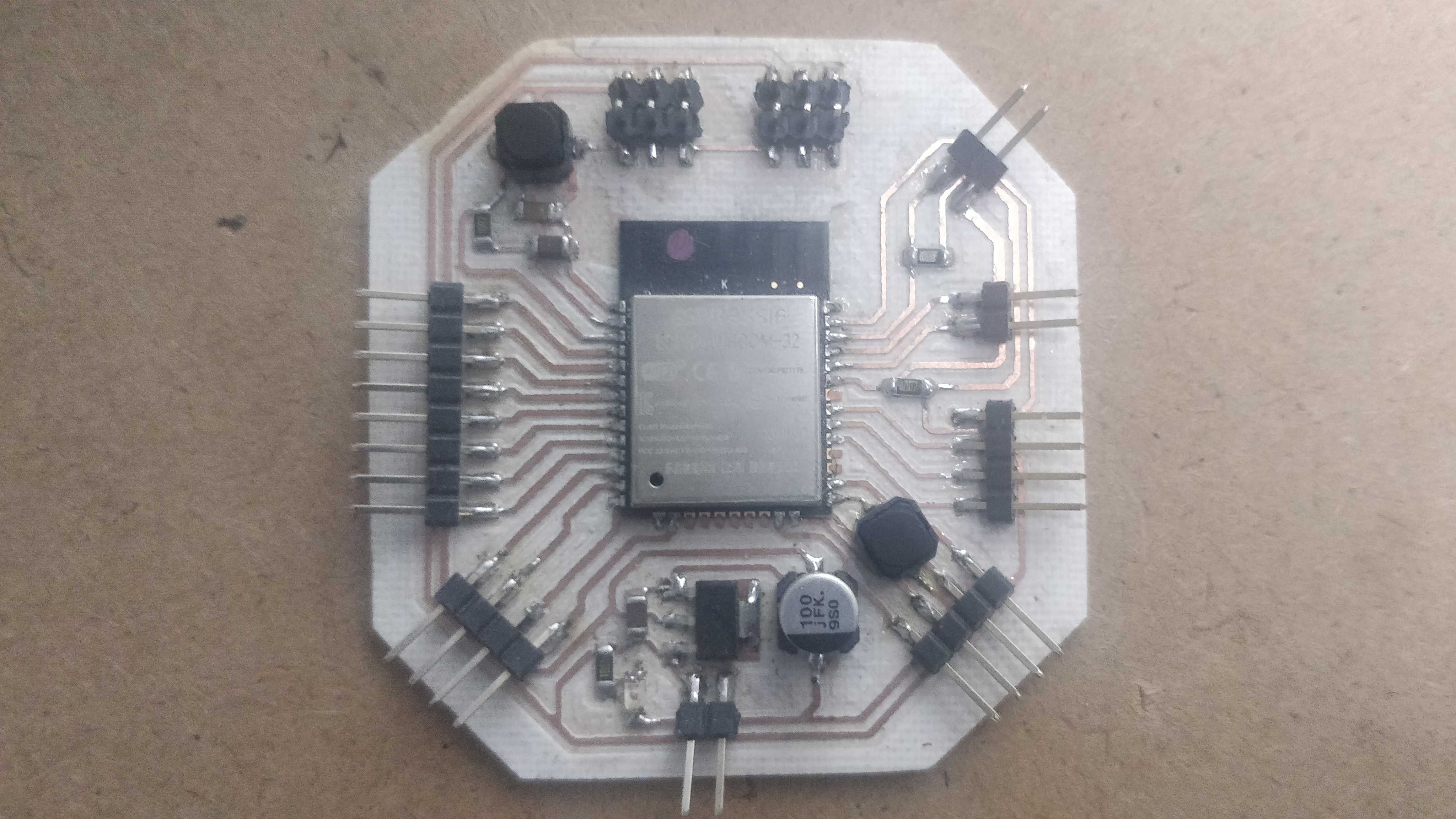
After obtainning the required components, I proceed to solder the componets to the board. Since, I did not know the sensiblity if the ESP32 I decided to solder all the other components first and at make a verification process to see that everything was workind as expected. At the end, I soldered the ESP32 to the board and the final board can be seen below.
Output circuit for Axolbot
There is another important board for the Axolbot which is a board that can manage up to 16 servomotors or 12 servomotors and 4 motors. I need to look for options to control so many devices that the ESP32 by itself cannot control along the input devices and the communication protocols. Thus, I started the creation process by selecting the devices that can help me to create this. After searching for options, I found out that there is one device widely used to control up to 16 servomotors which is the PCA9685. Regarding the motor driver, I wanted to limit the current limit up to 1.5A for continuous current and I found the DRV8833 which is a dual H-bridge Motor Drive that can handle up to two motors with 1.5A RMS and 2A peak per bridge.
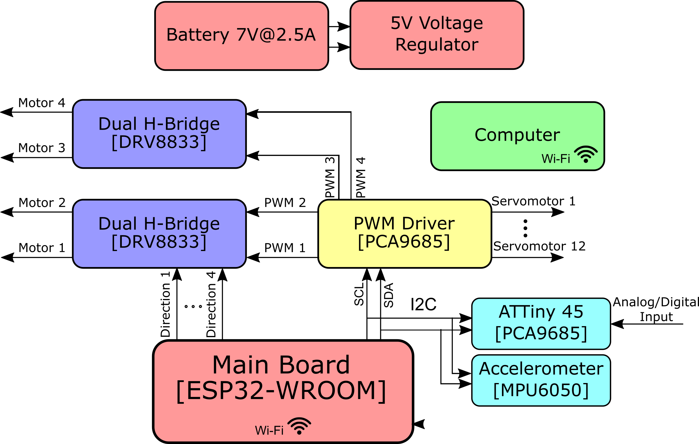
The idea of this board is that the servomotors will be controlled trough I2C from the main board while the dual bridges will be controlled through the main board and the PCA9685. The main board sends signals to control the direction of the motors while the PCA9685 sends PWM signals to control the speed of the motors. I created a functional diagram of the whole electric wiring of the Axolbot and it is presented below. The Output board contains the purple and yellow blocks.
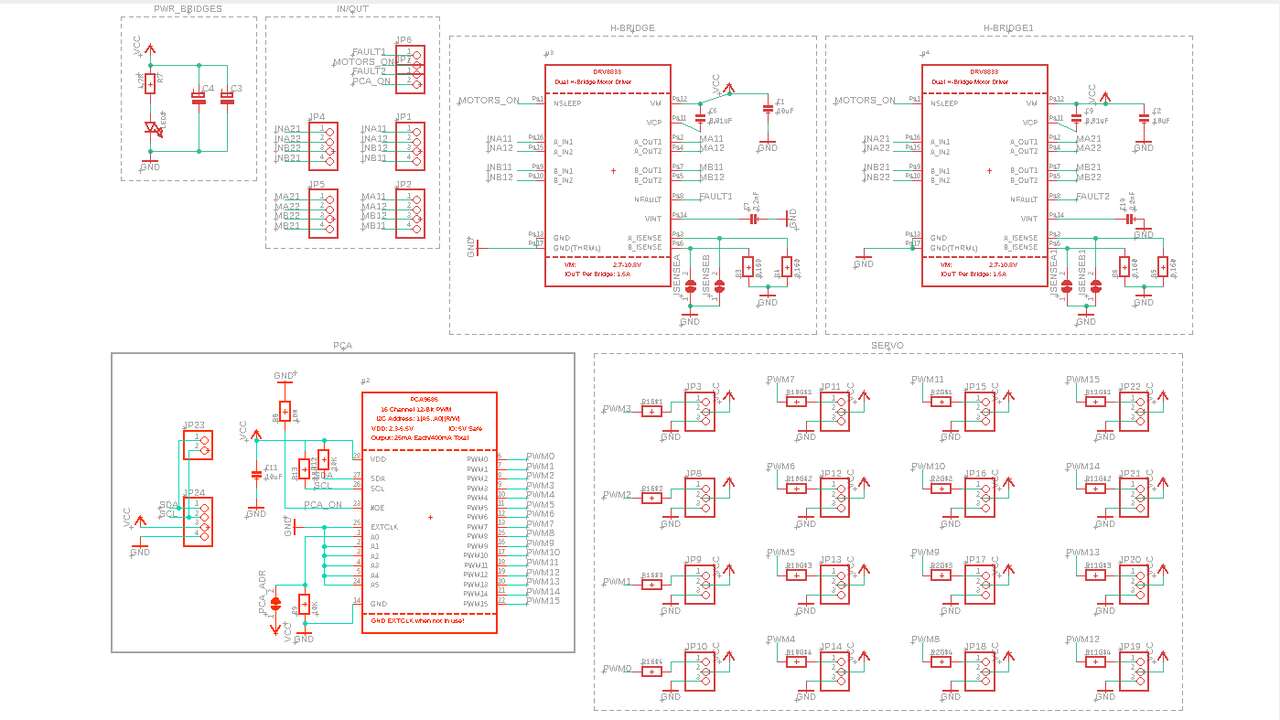
Now it is time to start my own schematics to create my output board, at the end the connection was not so hard since I already had the proposed connection from the datasheets. The most difficult part was to calculate the resistance that the dual bridges needs in case I want to limit the current. So, the datasheet says that the required resistance to limit the current is equal to 0.2 V divided by the current limit. In my case I set the current limit at 1.2A which gives a result of 0.16 Ohms. After that calculation everything else was to follow the diagram in the datasheets. The figure above shows the final schematics for my great output board.
Before I started moving the components to arrange them and connect them. I imported the outline of my main board to fit everything in the same space. In case you want to do it you just need to select the outline, go to export->dxf and save it where you want it. Later you can go to the other fie where you want to bring the outline go to import->dxf and select the created file. After those steps were done you can move it where you want. So, my final boad is illustrated in the next picture.
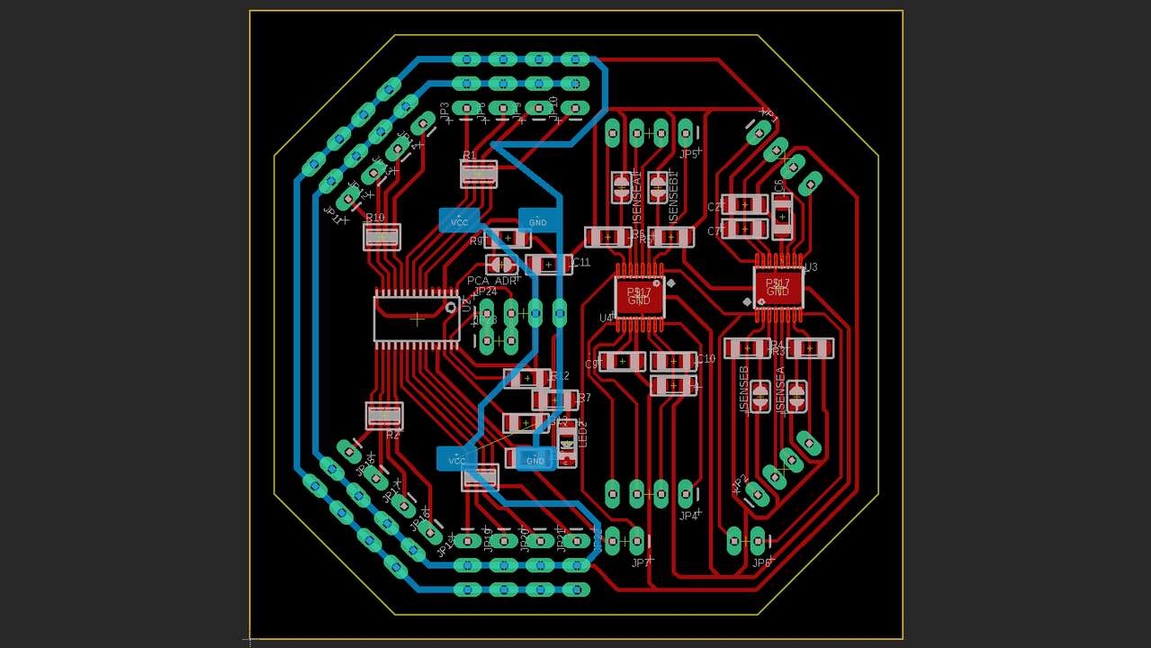
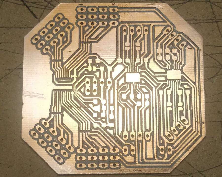
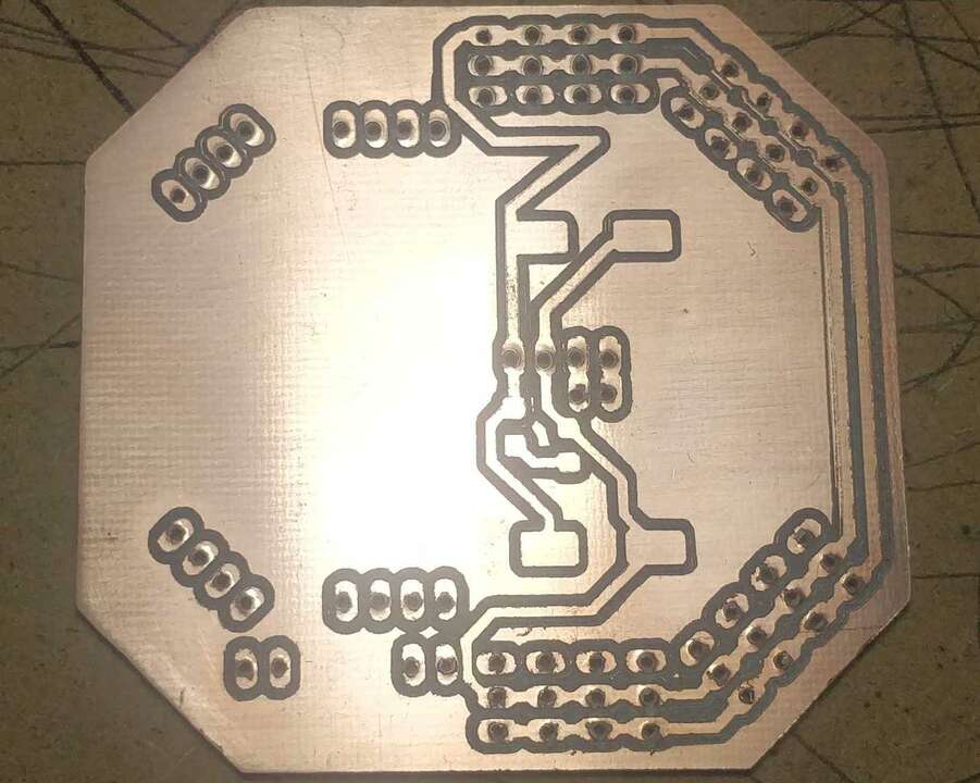
When the board was done, I saved the top and bottom traces because it is a double-sided board and the outline of the board. The following pictures represent the traces of the board where it is important to note that the bottom traces were mirrored horizontally to be able to machine the bottom layer since the board must be flipped.
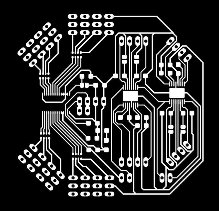
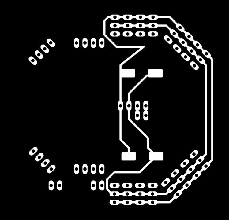
Another important point is that the ground and voltage signal have a bigger thickness to help in the dissipation process since the three devices can have a very high current consumption.
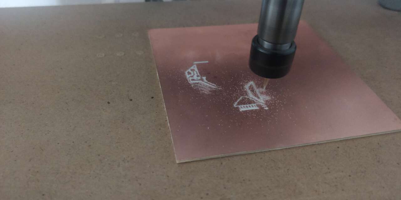
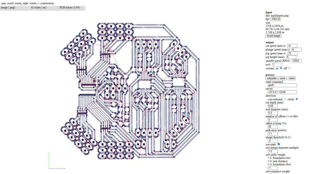
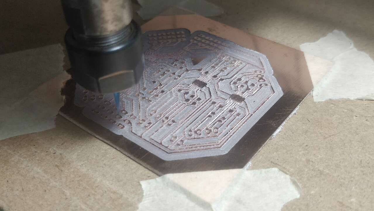
In order to machine the board, I used fabmodules to generate the G-code and I also used UGS to send the G-code to my Mini Router CNC 3018 PRO. The following pictures shows the top path generated in Fabmodules and the same path in UGS. When I was generating the path, I realized that the distance between pins of the DRV are too small that the 0.4 mm of diameter did not fit into the pins and I had to change up to 0.3 mm diameter in order to fit correctly. I am a little afraid that the pins will not come out well since they are too small and it is possible that the endmill will break them.
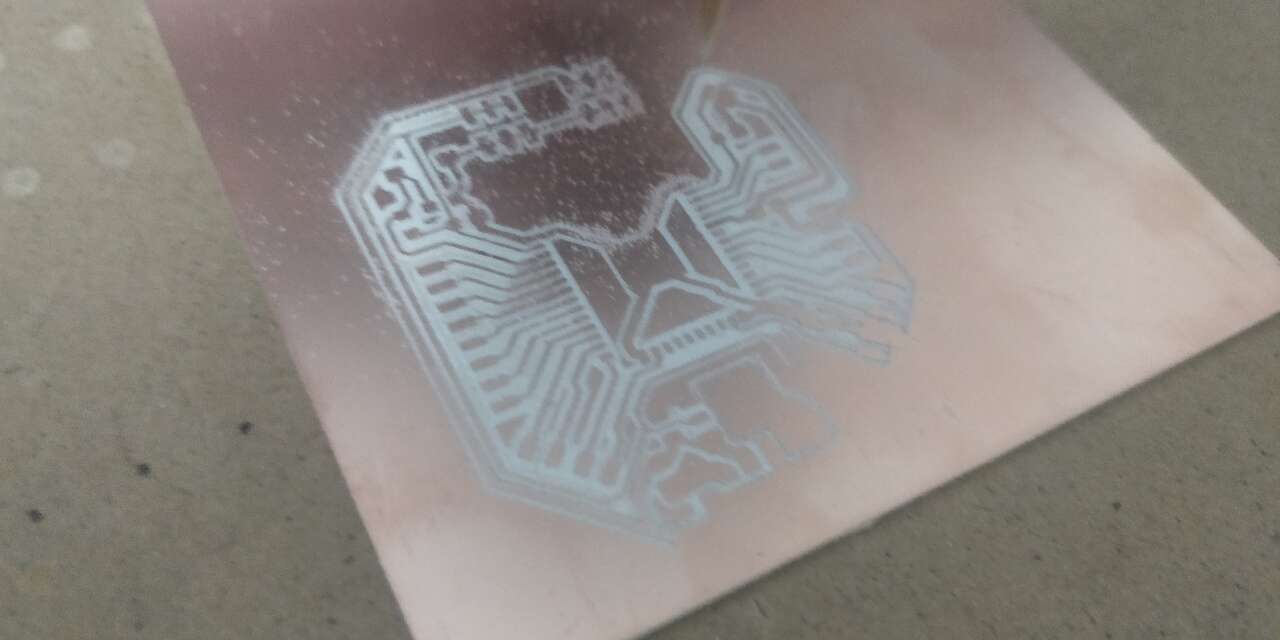
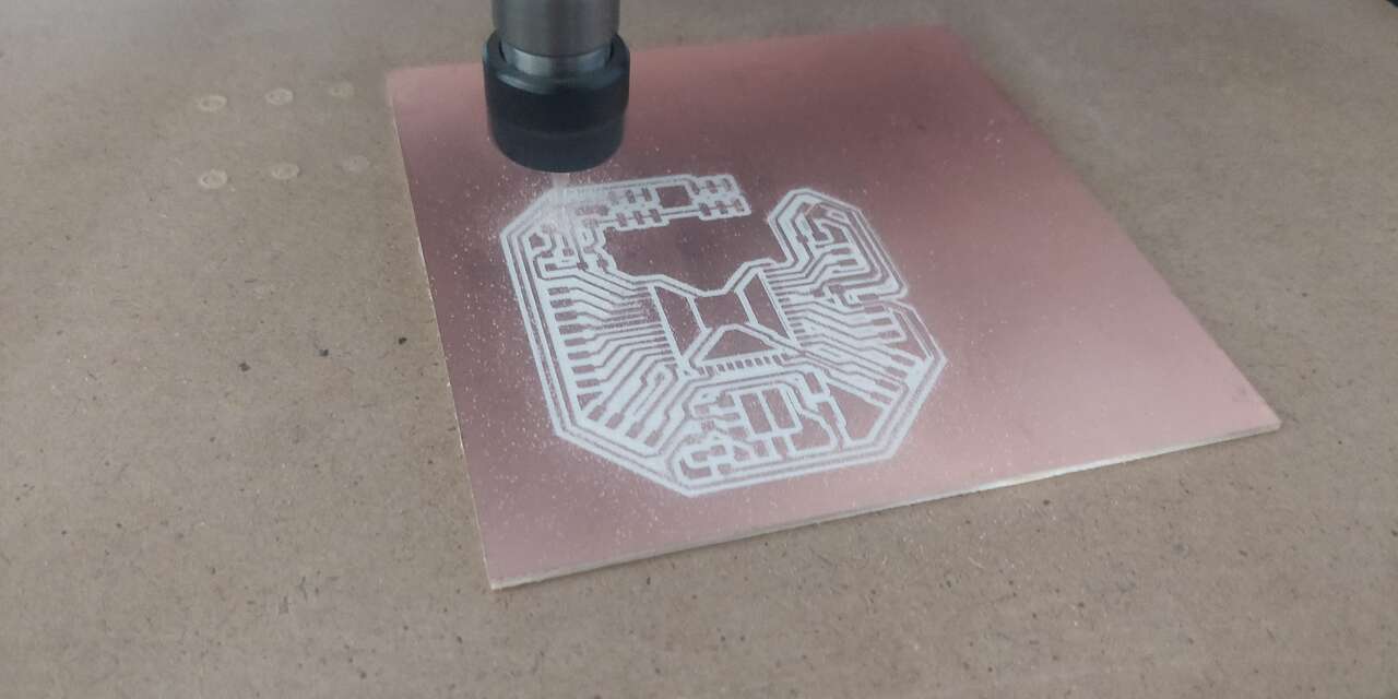
The three pictures above show the machinning process of the board. And I think they looked good :D.
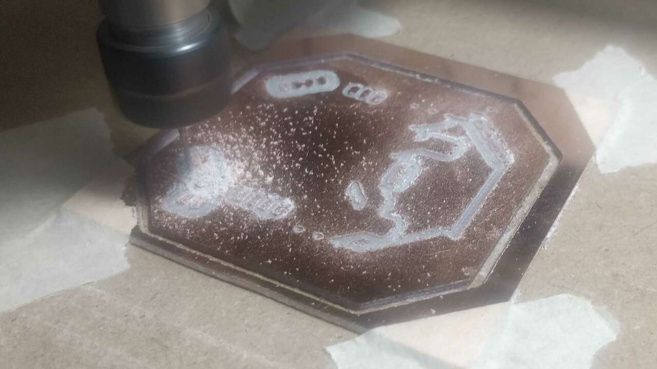
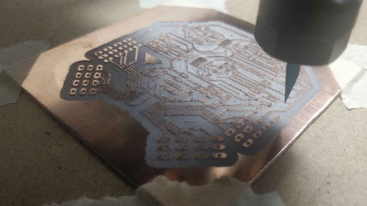
Once I finished both sides, I clean a little bit the board and I also remove some parts where the endmill did not fit. I think the board looks pretty good.
Before I started with the soldering process, I verified that all the paths and connectors were in the proper position and that there is continuity between signals. There were some paths were the endmill did not fit but I was able to remove them with a cutter. The following table shows the bill of material to create this PCB.
| Quantity | Component | Model |
|---|---|---|
| 1 | PWM generator | PCA |
| 2 | Motor driver | DRV8833 |
| 3 | Ceramic Capacitor | 10uF |
| 2 | Ceramic Capacitor | 2.2nF |
| 2 | Ceramic Capacitor | 0.01uF |
| 1 | Electrolitic Capacitor | 2200 uF |
| 4 | Resistor | 10k Ohm |
| 1 | Resistor | 4.7k Ohm |
| 4 | Resistor | 0.16 Ohm |
| 4 | Four resistor pack | 220 Ohm |
| 1 | LED | 1206 |
| 5 | Pin header | 1x4 trough hole |
| 16 | Pin header | 1x3 trough hole |
| 3 | Pin connector | 1x2 trough hole |
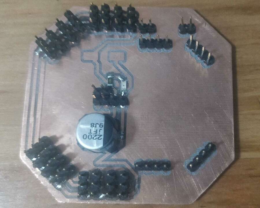
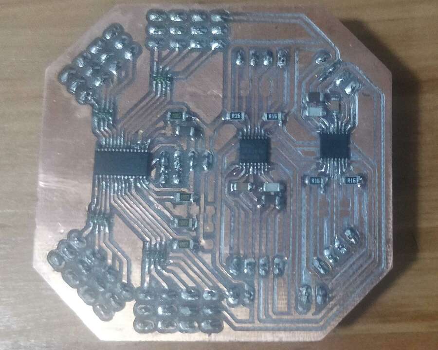
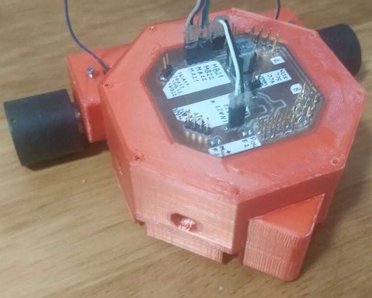
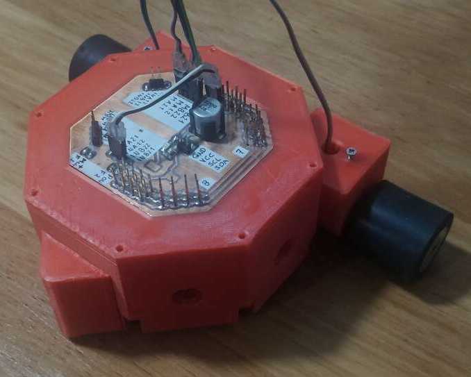
Once I arranged all the required components, I proceed to solder all the components on the board and I am really happy wiht the final product. Something important to note is that I have a two layers board and I had to solder from both sides the pins to have conductivity betwen both sides of the board since I could not find the couples that can fit inside and avoid solder the pins in both sides.
System Integration
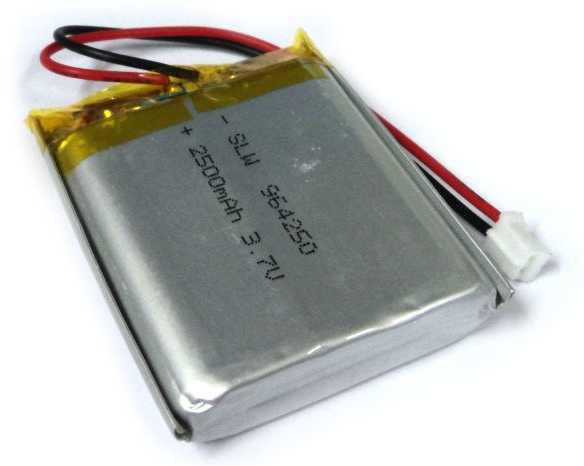
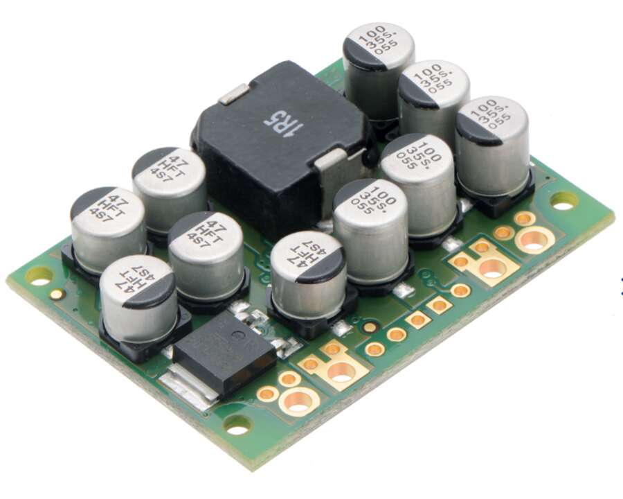
The system integration is very important since I must do it before I create the final program for the robot. I need to do it because Axolbot is a modular robot who is mobile which means that it does not have wires to communicate or power with the robot. The first step to make the integration is to find a way to have the main and the output boards with the battery and the voltage regulator inside the main module of the Axolbot. Thus, I need to find the best components to power the robot. I need a voltage regulator that can step down the voltage to 5V and that can provide with more than 10 A since there is a possibility that 16 servomotors are actuated at the same time. And the second component is that I need a battery with two cells to provide 7.4V and with as much current as possible to have longer working time.
After seraching in many places, I found the perfect fit for my robot in SanDoRobotics which is an electronic shop in Mexico. I selected a D24V150F5 which is a step down regulator that provides up to 15A at 5V, this regulator was designed and manufacture by pololu and its datasheet can be found here. Regarding the battery, I chose two LiPo cells of 2500 mAH that i can connect in series and got 7.4V and 2500 mAh. The following pinctures provided by SanDoRobotics shows the regulator and the batteries.
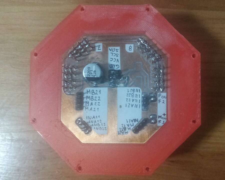
My first idea was to create a lid for my main module that can contains the output board and the voltage regulator. The iamges below show how this lid looked like when I place the output board. The regulator would have been place where the black screws are.
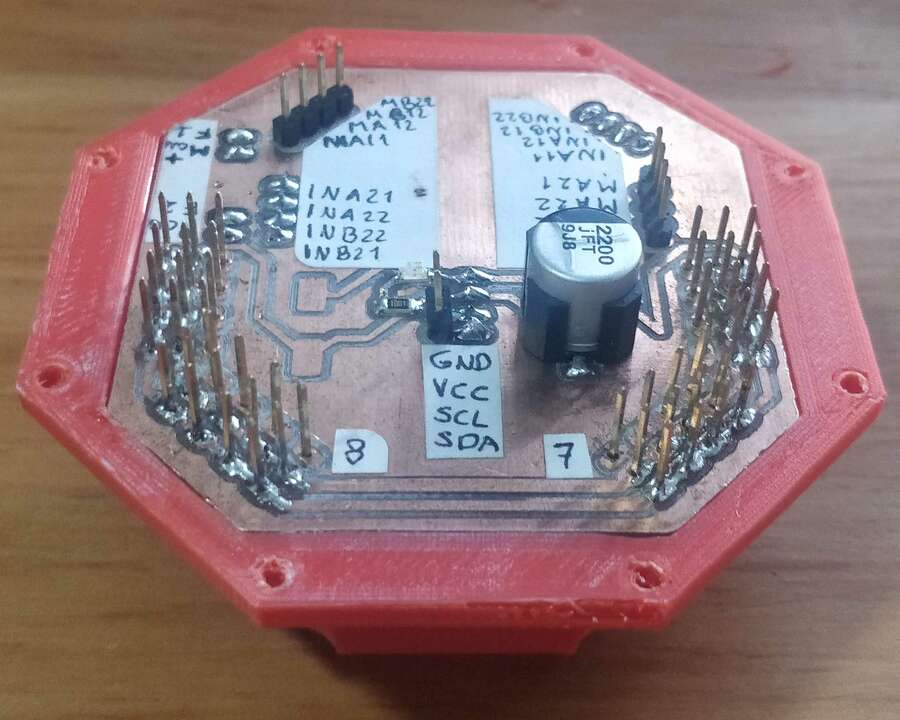
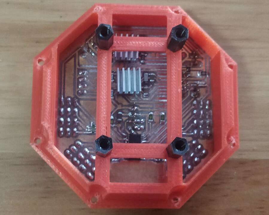
At the beginning, I though it was a good idea but later I found some problems such as, in case that there is a problem with the regulator it could damage both boards, the output board and the main board because the regulator was placed in the middle; another reason is that the wires could not fit in the thickness that I already have for the main module so I had to create somethign bigger. After analyzing these problems, I designed a second lid that would be at the bottom and that can isolate the batteries and the voltage regulator. In that way I can separtate the power from the control and there can be less problems in case something happens with the battery. The only problem is that I had to make a biger octagon so the batteries and the regulator can fit along the module.
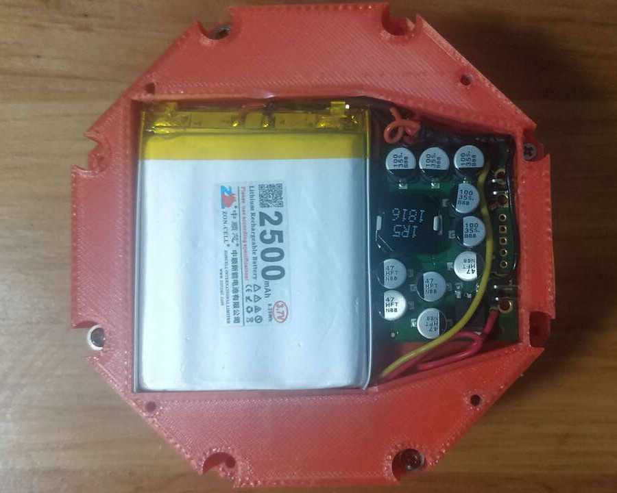
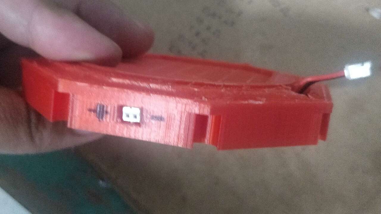
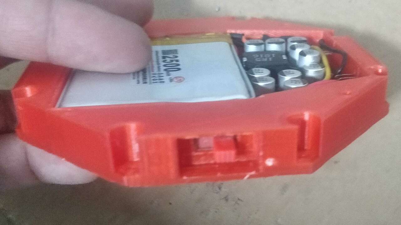
Since I would have an isolate power module, I decided to add a switch to power on and off the whole robot and another connector to charge the batteries without removing the screws and the lid of the power battery. These two features are shown below.
ike I mentionned before, I had to make a bigger main module so I had to change the top lid of the module for a bigger one and remove the part where the regulator was supposed to go since I already had it in the power module. The most important about this version is that all the boards are placed in the slot where the fit with a small pressure avoiding the movement of the boards.
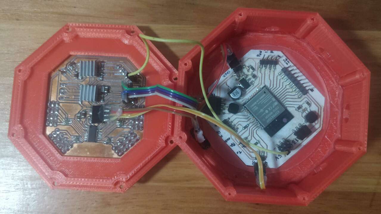
Finally, it is time to wiring all the electronics together. For this task, I followed the previous diagram shown during the development of the output board where all teh connection can be seen. The most important is that the power module goes to both board while the main board has an I2C connection to the output board as well as some digital pins to change the direction of rotation of the motors. The wiring can be seen in the folliwng image.
Programming the Axolbot
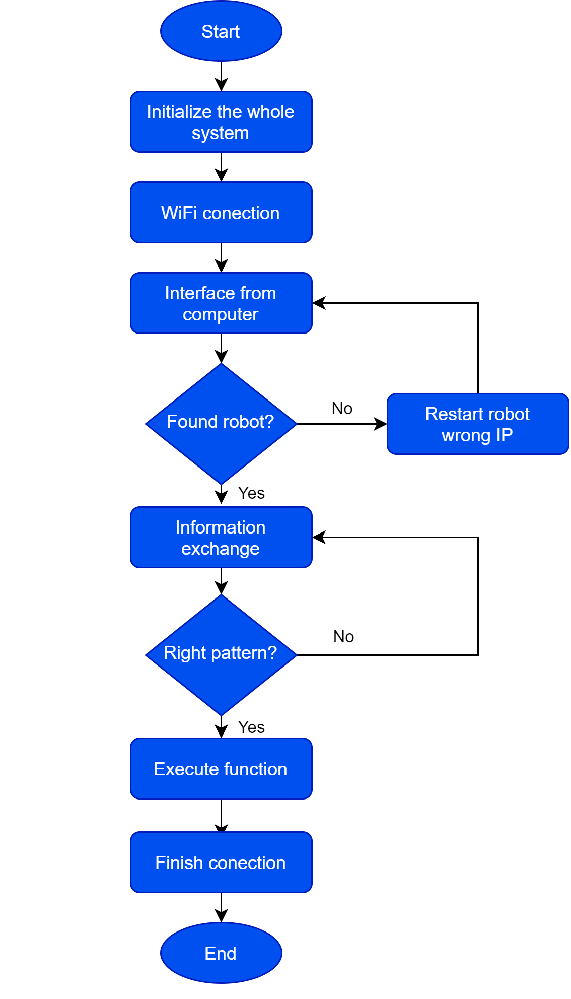
The program for the AxolBot is structured in such a way that a single code can be used for every single robot or configuration. Before I created tehe program, I decided to create a block diagram to see how the program must behave. The program must start by connect the ESP32 to the WiFi. Later, it initialize all the components and chips of the robot. The program must start the communicacion protocol between teh interface and the ESP. Later the prorgam must decode whatever information is sent by the computer to finally execute the required action. These steps are shown in the diagram below:
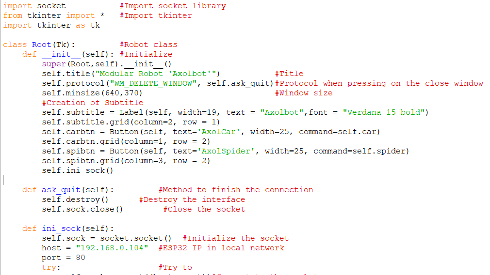
During the interface week, I created a WiFi connection between an interface created in Python and an Arduino code that were using sockets to interchange the information. Thus, I used that code as a base but I modified it to execute the required action that every robot needs. Nevertheless, I started modifying the Python code to access both robots from the same interface. The image below shows part of the Python code:
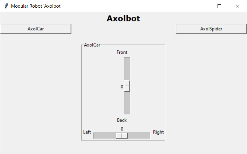
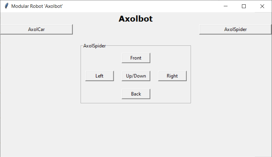
The interface lets you select between the configuration for AxolCar or for AxolSpider, the controls are different but the appear and disappear depending on the selection. AxoCar has two slider to control the speed to go to the fron or back and another one to go to the left or right. Axolspider has 5 buttons, the button in the middle is to stand up and stand down while the other four buttons are to move the robot around. Both configurations are shown below:
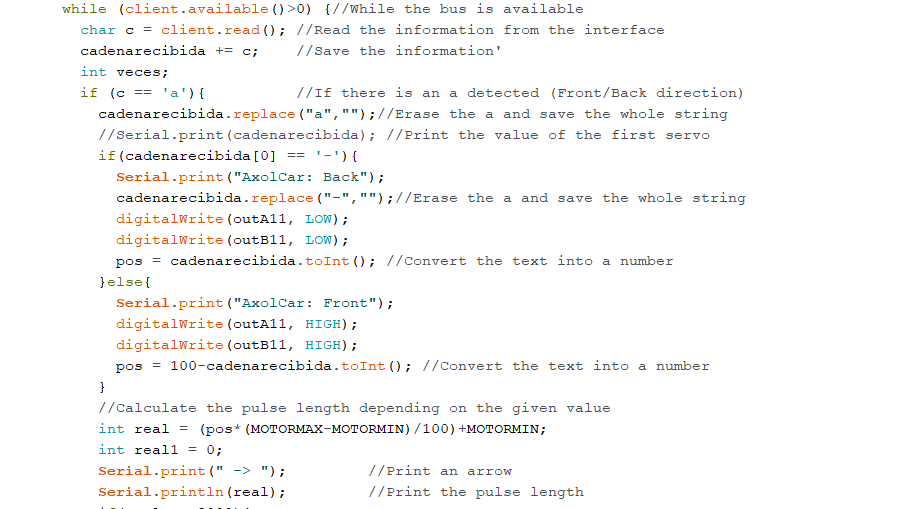
Regarding the Arduino code that decode the information given by the interface was a complicated but it was also worth it. First, I created the code for the AxolCar since it was the easiest. For the AxolCar the interface sends an a or z depending on the slider with the value of the slider (ex: a120, z50). Thus, the arduino code for the AxolCar execute the following steps:
- Reads the string sent by the interface
- Erase the letter a or z
- Convert the string to integer
- Change the direction of rotation depending on the sign
- Calculate the puse length according to the value
- Sends the required PWM to the right output
- Read another string
Part of the code is shown below:
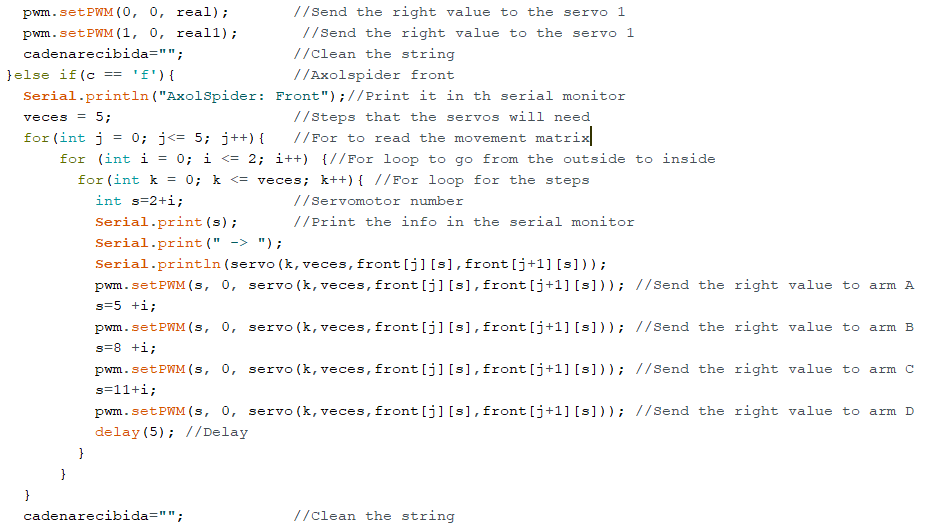
For the AxolSpider I used the same conditionals to sort the given information by the interface. However the steps that I programmed to make work the robot are different. First, I decode the received string, later depending on the information is where thecode must enter. Knowing the button that as clicked, I execute a routine that read the servomotor values froma matrix previously created and the sameroutine send the right information to the servomotors. Thus, the arduino code for the AxolCar execute the following steps:
- Reads the string sent by the interface
- Convert the string to integer
- Execute a routine dependiong on the pressed button
- Calculate the puse length according to the routine
- Sends the required PWM to the right output
- Read another string
Part of the code is shown below:
Packing for the Axolbot
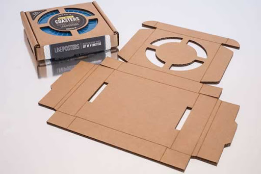
I wanted to create a box to save all the components of the robot and be able to move it from one place to another more easily while avoiding any possible damage that can be caused when transporting the robot. Thus, I started by searching some cardboard boxes that I can use to create my own file and I found the following picture that I used to created my own version.
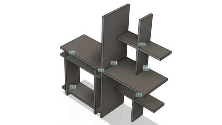
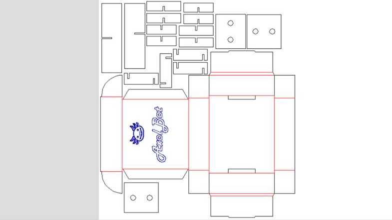
Knowing the shape that I need and the dimension of the accesories, I started by creating the inner walls of the box to know how everything will be placed and the dimension of the box that I will need. After I designed the inner wall, I proceed to use the previous picture to draw y own version of the box like the following pictures shows:
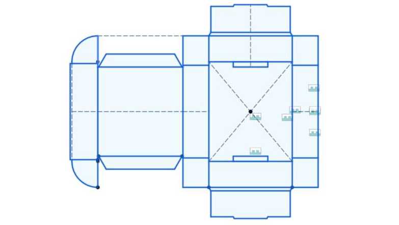
With the vector of each piece and the whole box, I put togheter all of them in a single file to be sent to the laser machine and also to know how large teh cardboard must be. The following picture shows all the vector togheter.
The video above shows part of the cutting process in the laser machine.
Once the pieces were cut, the assempling process was really fun and you can take a look in the next video:
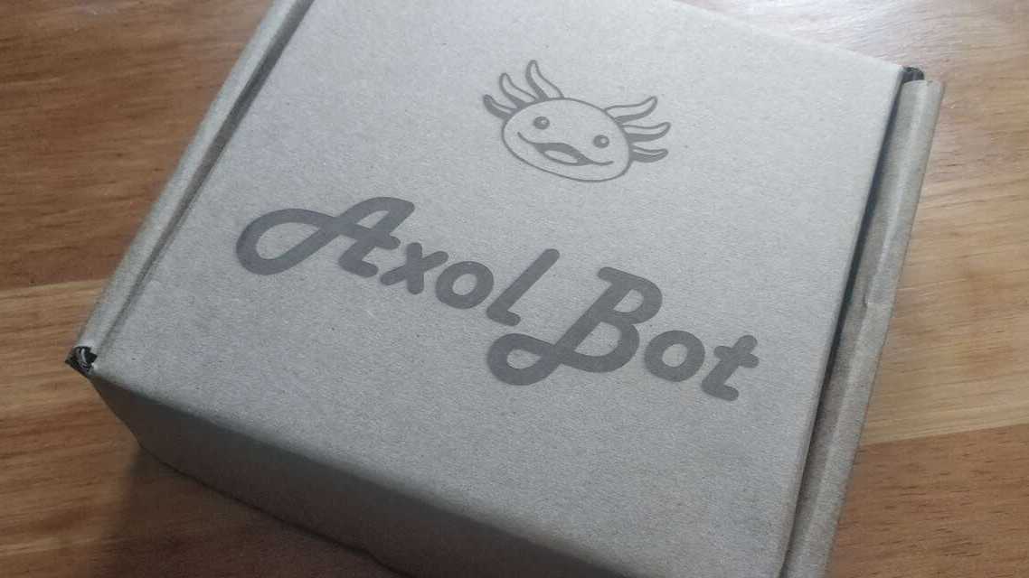
The box from the outside looks like the picture above
AxolCar
The AxolCar is really easy to be created, you only need the two accesories for the motor and the accesory that simulates an universal wheel since we only have two wheels for this configuration. The idea is that you have to put the pieces just like the image below:
Regarding the connection you must use the pins of the H-bridge that is in the center of the board because the code use that driver. Thus, both motors go in that driver. You also need a connector that sends two PWM from the port 0 and 1 of the PCA9685 to the input of the H-Bridge just like the two image below show. In case that the orientation of the wheels is inverted you can simply invert the wires of the motor in the board.
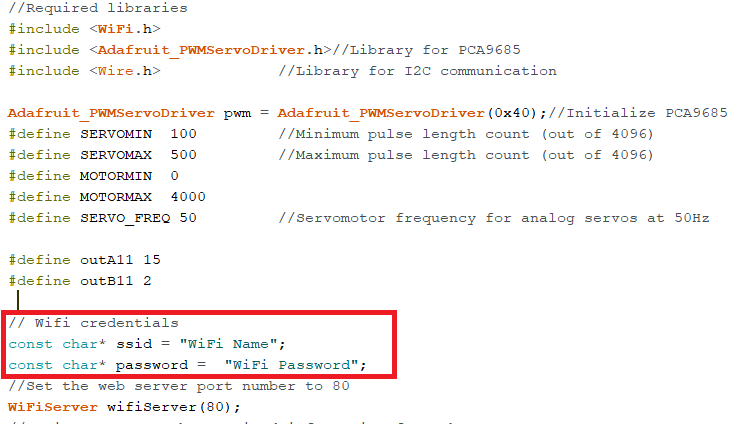
The code is the same for both robot but you must modify the credentials in the Arduino code just like the image below shows:
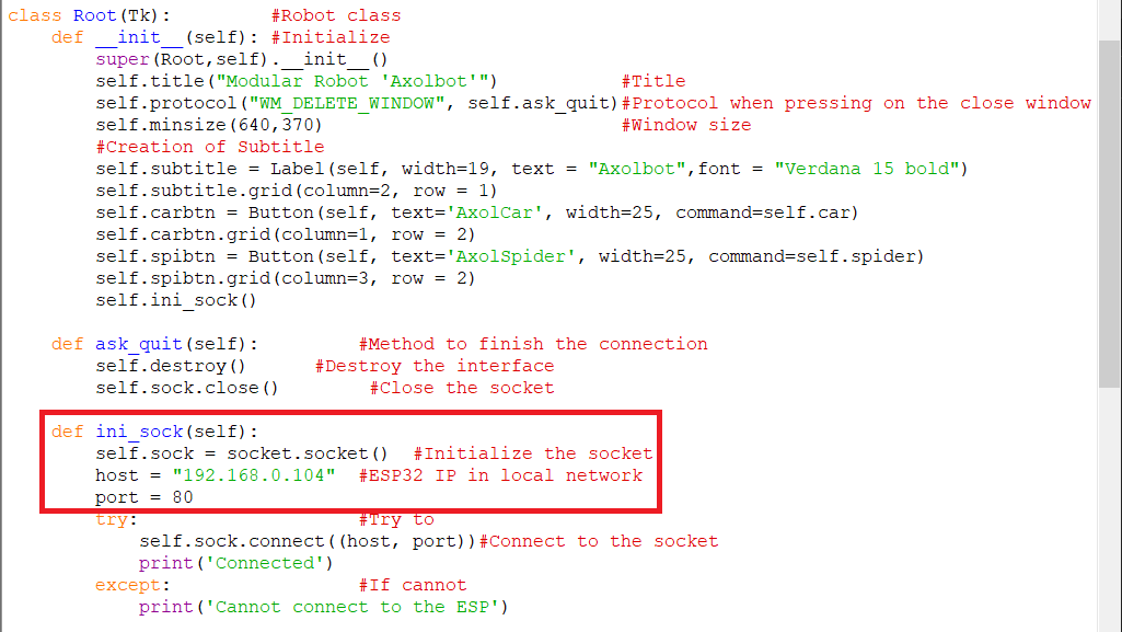
Now it is time to program the board with the Axolbot program. The ESP32 uses Tx and Rx to be programmed, therefore you will need to connect four wires to the robot; two for the power and two for the communication. Remember that Tx of the programmer goes to Rx of the ESP and viceversa for the Rx. If you want to see more examples and information about the programming process you can go the Embedded programing week to see how the board was programmed. Once the program is in the robot you must leave the Tx, Rx and teh GND wires because the robot will send the IP address of the robot after the connection was done sucessfully. The next step is to take the IP address that is given to you from the monitor and paste it in the Python code in the socket configuration just like the image belos shows:
The last step was donde in Python IDLE in case you do not have it you can go to my Interface and application programming week. When you run the interface in Python and if everthing went right you must see a message in the Python screen that says Connected.
The interface for the AxolCar is really easy, you just have two slider a vertical and a horizontal one. The vertical sends a signals to go forward and backward depending on the slide's position while the horizontal sends a signal to turn to the right or left and as well depends on the slide's position. The interfacte of the AxolCar is show below:
Finally a video of the AxolCar working is shown below:
AxolSpider
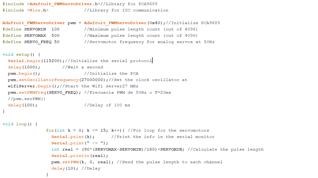
The assembling process of the AxolSpider is more complicated than the last one. The first step is to upload a program into the robot that sets all the PWM channels to move the servomotor at 90 degrees so we can place the shaft and the accesory in the right place. The code is shown below:
When the code was uploaded, we need to assemble 12 servomotor with its accesories, just like the two pictures above shows:
Later we need to assemble the arm without putting the shaft accesory of the servomotor. Thus, we power the robot and let the servomotor moves to 90 degrees just like the image below shows:
Later we must move the c-holder of the servomotor at the right position and place the shaft accesory with its bolt. The idea is that we need to do exactly the same for the 12 servomotor or 4 arms.
The next image show the final result of a single arm where I used fasteners to hold the wires and to avoid any damage to them.
When the four arms are done, we can proceed to put the four arms into the main module and connect the servomotor. I create a diagram that shows the output channel of each servomotor as well as the maximum and minimum movement that each servomotor can execute in degrees.
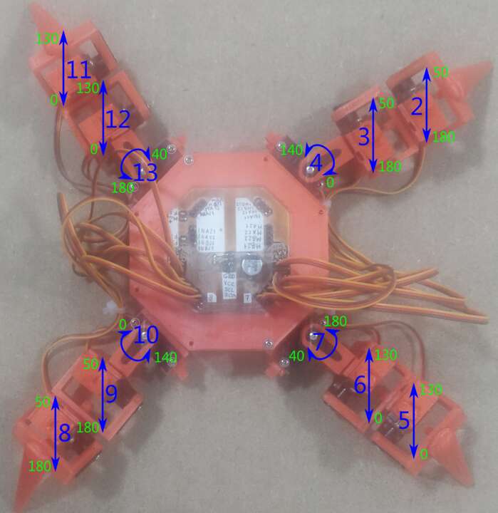
Now, we are done assembling the robot and we just need to upload the Axolbot program to be able to move the spider.The interface for the AxolSpider is really easy, The button in the center is to stand up and down while the other four buttons are to move depending where you want to go.
Finally a video of the AxolSpider working is shown below:
Files created
Electronics
- Outline Axolbot V2.0
- Traces Axolbot V2.0
- Traces Input Board
- Outline Input Board
- Top Layer Output Board
- Bottom Layer Output Board
- Outline Output Board
Mechanics
Programming

This work is licensed under a Creative Commons Attribution-NonCommercial-ShareAlike 4.0 International License.