Embedded programing
Microcontroller Architecture
There are two basic modeles which represent two different ways of exchanging data between CPU and memory, these two types are:
- Von-Neumann architecture
- Harvard architecture
There first image represents the data exchange between the CPU and the memories (RAM + ROM) in a Von-Neumann architecure while the second image shows how the CPU sends/recieves data from and to the independet memories.


Nowadays, the microcontrollers with Harvard architecture are called RISC microncontrollers while the microcontrollers with Von-Neumann's architecture are called CISC microcontrollers. Harvard architecture is newer than the Von-Neumann's, and one of the main difference is that the data bus and the adress bus in the Harvard architecure are separated. This characteristic allows that the microcontrollers with Harvard architecture have a grater flow od data through the CPU and also a greater speed of work. This difference and the ways of exchanging data between CPU and memories can be observed in the next picture where the general diagrams of both architectures is depicted.

Datasheets
To better understand the datasheet, first I read the datasheet of an ATtiny44 because it is the only microncontrollers that I have at the moment, well I have it on the programmer that I created in previous weeks. The ATtiny44 belong to the same family as the ATtiny24 and the ATtiny 84. While reading the data I could notice that the main differences between these tree microcontrollers are in the non-volatile program and data memories, these differences can be observe in the next table:
| Microcontroller | Flash memory | EEPROM memory | SRAM memory |
|---|---|---|---|
| ATtiny24 | 2K byte | 128 bytes | 128 bytes |
| ATtiny44 | 4K byte | 256 bytes | 256 bytes | ATtiny84 | 8K byte | 512 bytes | 512 bytes |
But what does that memories really mean or what is their purpose inside the microcontrollers?. After reading some articles I came to the conclusion that the Flash memory is the memory where the program is saved and where the micrcontroller reads the given instructions. The EEPROM memory is a useful memory to save data for long periods, for example if we need to stora the specific value of a variable, we can use the EEPROM to save it. Finally, the SRAM memory is where the microcontroller stores the values of variables created by a sub-routine or variable that were not initialized but after a processing they get a value. Thus, each memory has an specific function and they are as well as important but depending on the project size you might want search for a viable option.
Now, all these microcontrollers have a RISC architecture which means that they use a Harvard architecture, they can handle up 120 powerful instruction in a single clock cycle. This is important to know because while more instructions can be executed in a single cycle, the smaller is the processing time. Regarding the peripherical features I saw that they have two timer/counter of 8 and 16-bit with two PWM channels, these parameter is important to handle up to two PWM with a resolution of 2^8 or 2^16 They also have a 8 ADC with a resolution of 10-bit, this is an important parameter when you know that you will have an analog input and you need to know the specific voltage value of that input, these microcontrollers have a resolution of 5/(2^10-1) which means that for each bit we have a voltage of 4.88 mV
The previous pins that I explained can be seen in the following pictures which show the pin distribution depending on the package as well as the main characteristics that each pins can execute.


According to the pinout we know that the microcontroller has the following pin description:
- VCC: Supply voltage
- GND: Ground
- Port B (PB0 ... PB3): Digital I/O with internal pull-up resistors
- Port A (PA0 ... PA0): Digital I/O with internal pull-up resistors but they are also analog input fir the ADC, analog comparator, Timer/Counter, SPI connection, and interruptions
- RESET: Reset input activated with a low level voltage
Datasheet for the ESP32
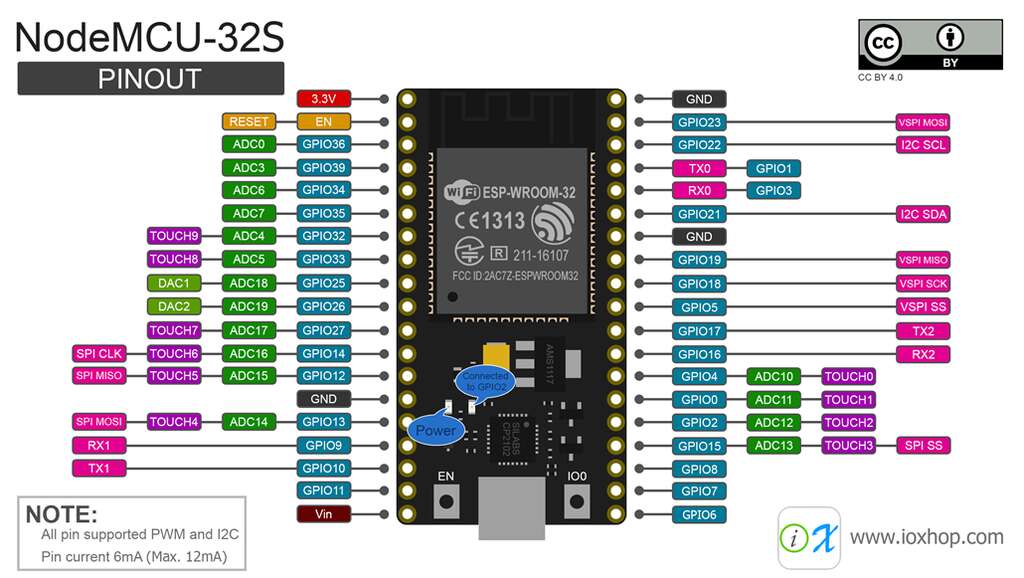
Since I want to use an ESP32 for my final project, I will also analyze the datasheet of this MC. The first thing I saw is that the ESP32 has an Xtensa dual-core 32-bit LX6 microprocessor. So, each instruction is of 32-bit and we can make operations in the range of 32-bits which is important when we want to have high precision. It has a ROM memory of 448 KB for booting and core functions and it also has a 520 KB SRAM for data and instuctions. Another important feature of the ESP32 is that it has two really good connectivity devices, a WiFi 802.11b/g/n and a Bluetooth LE. The following picture shows the pinout of a board that uses the ESP32-WROOM that is exactly as the pinout of the microprocessor with the diference that the presented board has a voltage regulator where the input is the Vin.
The main interfaces, that the ESP32 has, are:
- SD card: It works as an external memory to save data (It is mainly used when you have a Camera)
- UART,SPI,SDIO,I2C: Communication protocols to make an exchange of information between the MC and the external world
- LED PWM, Motor PWM: Generation of PWM to control devices such as LED or motors that require a PWM signal
- Pulse counter: This pins can count when there is a pulse signal. It is really helpful when you want to read the steps of an encoder
- GPIO: These pins are the General Purpose I/O and they can be used as an Input or Output depeding on the requirements
- Capacitive touch sensor: This interfacas can make a difference between a person touching a pin or when he/she is not
- ADC/DAC: Converter from Analogic to Digital and viceversa, these pins allows the user to read or write an analog signal
Something that it is important to note is that this microcontroller does not use 5V as a power supply but instead it needs 3.3 V. This is important because there are many sensors that must be powered by 5V or that their outputs are give 5 V. Nevertheless, this characteristic was implemented into my PCB design to avoid any possible damage.
Programming the ESP32
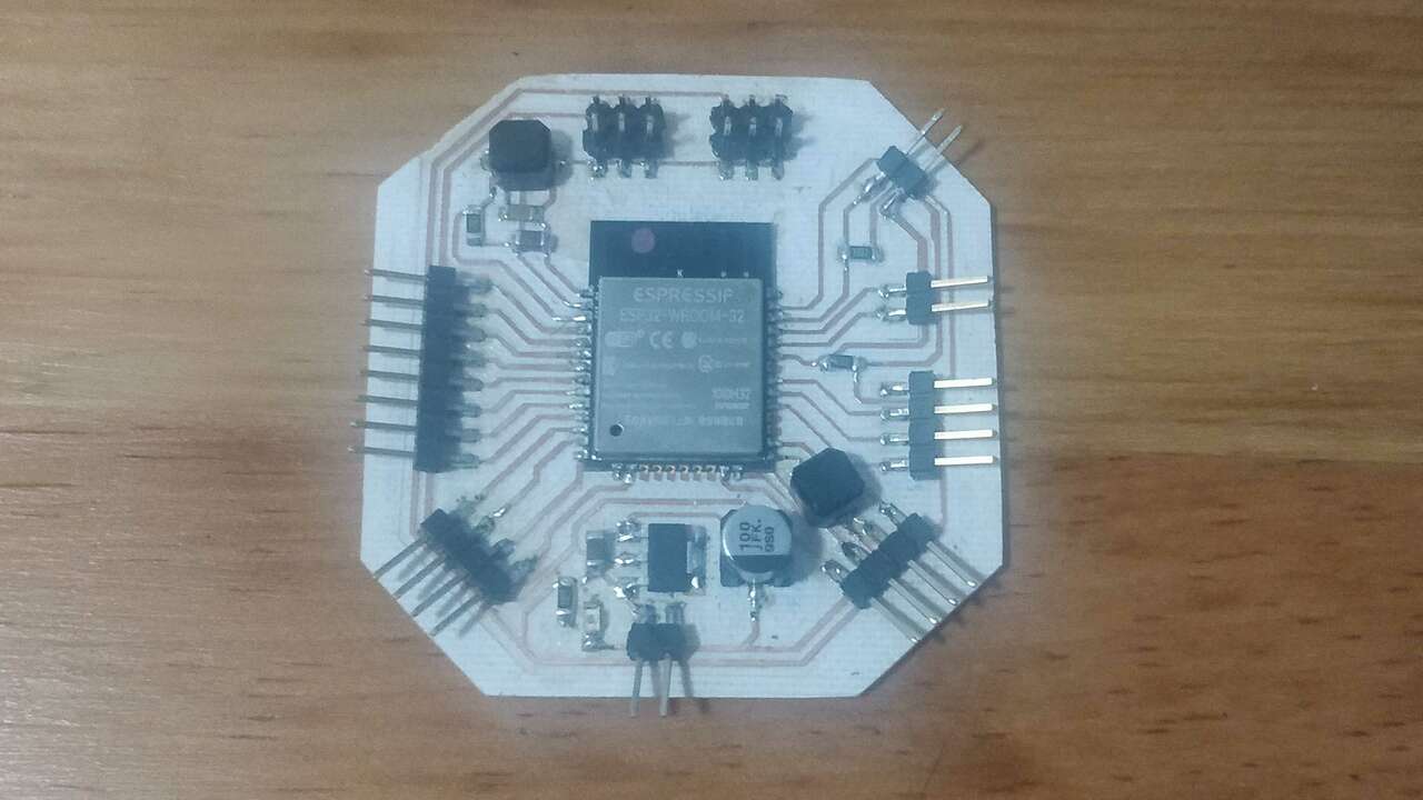
I used the board created durign Electronic Design week, where I developed two version but I just created the second version of it. This version is shown below.
ESP-IDF PowerShell
First, I wanted to use Espressif IoT Development Framework (IDF) and I used the following tutorial to do it. I used my computer with windows to install it. Thus, I download the executable file by clicking on the windows icon and wait for it to be done. When the file was fully downloaded, I start the installation process as the next pictus shows.

After a few minutes the installation is finished and we can proceed with the next step, which is openning the ESP-IDF Powershell. The icon is shown below and after the icon was clicked a new window where the initialization of the software is executed.


After oppening the ESP-IDF software, we need to go to the hello_world folder and set the target to be used in the software. Also, we need to open the menu configuration wiht the following lines:
				cd .\hello_world\
idf.py set-target esp32
idf.py menuconfig

If everything went as planned, you should see the following picture that depicts the configuration menu. This menu can be used to set up project specific variables, such as Wi-Fi network name and password, the processor speed, etc. However, for the hello world example is not neccesary.

Now is time to build the project by running the next line
idf.py build
The building process took me a while since there are many dependencies that need to be built. The next pictures show the process from the beginning to the end.


After we built the program, we need to flash the program onto the device with the following code:
idf.py -p PORT [-b BAUD] flash
where the port can be obtained from the device manager just like the following picture shows

In my case is the COM9 and the baudios can be set to an especif speed. However, if the instruction does not contains the baud, the system will use the default speed which is 115200.

The next step is to use the monitor to see the execution of the program. The monitor code is shown below where the most important is to use the correct COM port.

In case that the previous steps were exectuted in the right way and that there were no errors. You should see the following screen that shows the hello world program with its execution and the result.

Since I will be using the WiFi of the ESP32, I executed a program that was on the ESP-IDF software. I move to the examples folder to see if there were any code realted to the WiFi by conding:
				cd .\examples\
ls
cd .\wifi\scan\

What I did next is a good practice in case you do not want to repeat all the previous steps, since we can write one command to execute, flash and run the program which is the following:
idf.py -p COM9 flash monitor

After writting that line, the software executes everything untill the program in uploaded to the ESP32 and it runs the monitor to see the serial communication to the shell. The software must display the available WiFi that the ESP32 can find as the picture below shows.

The following video shows the programming process until the program is working and the WiFi networks are shown.
Arduino IDE
Now, I will use Arduino IDE to program my ESP32 board since it is one the most easy platform that can be used to program nowadays. Since the ESP32 is not a default board that is included in the default version of the Arduiono IDE, we need to updload a JSON file to be able to select the ESP32 board. To add the JSON file, you must go to File -> preferences in Arduino and in the section that is called "Additional Boards Manager URLs" add the following text:
https://dl.espressif.com/dl/package_esp32_index.json
In case you have added previous Board Managers, you must add a comma between both URLs

Now the Arduino can access the board manager but it must be downloaded to the Arduino IDE. Thus, go to Tools -> board -> Board Manager and a new window will be displayed. In this window search for esp32 and the only option that will be shown must be installed to add the esp boards.


If everything went as planned, you must be able to select the ESP board. In case you are using the same ESP as mine, you can select the ESP32 Wrover Module like the picture above shows.

When the board has been selected, we must verify that the ESP parameters are good especially the Upload speed and the Partition speed. Nevertheless,, the rest of parameters are also important.

The next step is to program the board with some kind of code. Of course I selected a code that search for the Wifi networks and later it connects to the one with the given credentials. This code can be found in the following link
Once the board has been program you must see the following screen in the serial monitor. Well, you will not see exactly the same because you the WiFi networks near you will not be the same as mines.

The video above shows the programming process and the serial monitor where the wifi networks and the connection to the Wifi is stablished.
Files created
Useful Resources