9. Embedded programming
1. Weekly Brief Summary
2. Weekly Assignment Requirement
Group assignment:
- Compare the performance and development workflows for different microcontroller families
- Document your work (in a group or individually)
Individual assignment:
- Read the datasheet for the microcontroller you are programming
- Program the board you have made to do something, with as many different programming languages and programming environments as possible.
3. Group Assignment
FabLab KAMAKURA 2021 Lab site / Embedded-programming
4. Read datasheet
I skimmed through ATtiny3216 datasheet and picked some information.
- One of AVR 8-bit CPUz, made by Atmel company
- 32/16 KB In-system self-programmable Flash memory
- 256 bytes EEPROM
- 2 KB SRAM
- Write/Erase endurance is 10000(flash), 100,000(EEPROM)
- Data retention: 20 years at 85°C
- UPDI(Unified Program and Debug Interface)) Supported, that means single pin programming and debugging is possible
Pin Assignment
ATtiny3216 has two differnt shapes. SOIC means Small Outline IC with L shaped read lines for 2 sides.. VQFN is a type of Quad Flat package, has pins for 4 sides. I will use SOIC type as Fab Academy basic style.
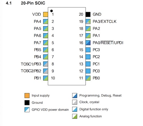
- PIN1 for VCC
- PIN8 for RXD
- PIN9 for TXD
- PIN10 for SDA
- PIN11 for SCL
- PIN16 for UPDI programming
- PIN20 for GND
- 12 PINs for Analog/Digital
- 6 PINs for Digital
I feel it has fluent input/output, digital/analog pins for my final project. Also has RX/TX for serial, SDA and SCL for I2C communication.
Power and Current
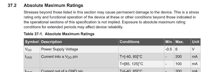
Power supply voltage needs to be lower than 6V. It should be nice to control by USB power supply 3.3V from laptop, 5V from mobile battery or USB power adapter.
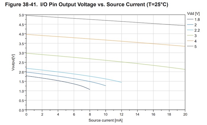
If I ran ATtiny3216 by 5V, I/O Pin output produce around 20mA. This number will be used as reference to choose other components.
5. Compare microcontrollers
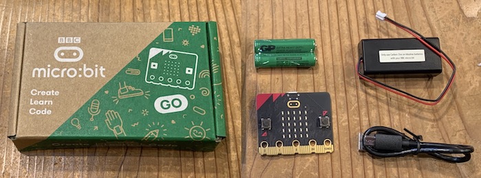
micro:bit
The micro:bit is a board developed mainly by the BBC, and is often used in STEM education.
| part | spec |
|---|---|
| MCU | 32 bit ARM Cortex M4base Nordic nRF52833, 64MHz, with BLE |
| RAM | 128KB |
| LED | 25pcs, can use as light sensor |
| Swith | 2 |
| Touch Sensor | 1 |
| Speaker | 1 |
| Microphone | 1 |
| Acceleration sensor | 1 |
| Magnetic force sensor | 1 |
| Size | 43 × 52 × 11 mm |
| Weight | 9 g |
Programming is done from a web browser. It was a block-based no-code environment, and the conditional branching and use of sensors was intuitive and easy to understand.
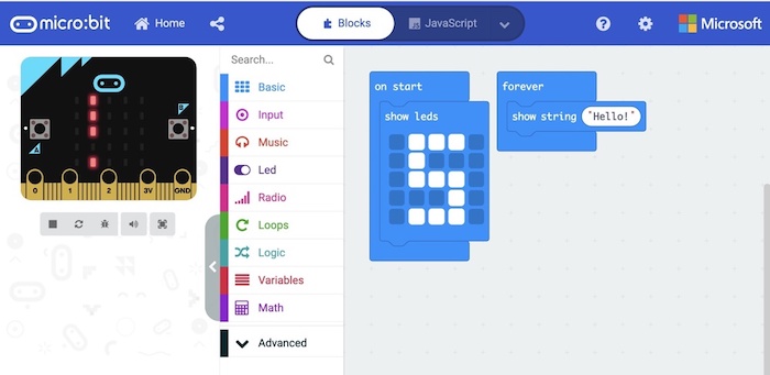
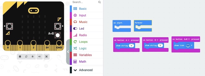
I try to detect touch and play sounds program.
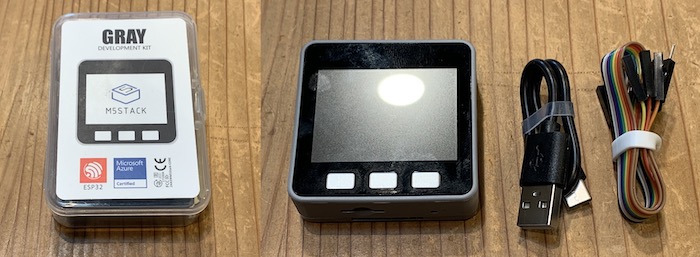
M5 Stack
M5 Stack is equipped with ESP32, it can handle Wi-Fi and Bluetooth communication and can be developed in the Arduino environment.
| part | spec |
|---|---|
| MCU | MPU6886 + BMM150 |
| Interfaces | SPI x 1, I2C(GROVE) x 1, UART x 2, I2S x 1, microSD slot x 1 |
| LCD | 320 x 240 Color TFT LCD |
| Speaker | 1 W |
| Vattery | 3.7 V / 150 mAh |
| Tempreture | 0 ~ 40℃ |
| Size | 54 × 54 × 17 mm |
| Weight | 120 g |
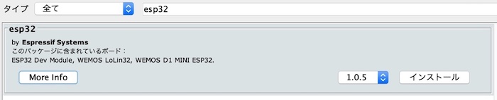
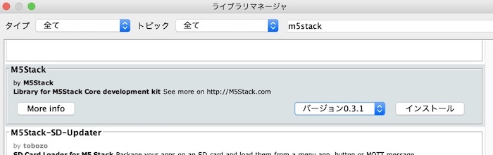
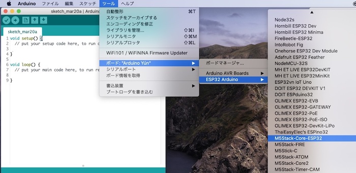
When programming from Arduino, have to add esp32 board, include m5stack library. In case of M5 Stack Gray, choose M5 Stack-Core-ESP32.
Then, I ran random triangle showing program.
#include <M5Stack.h>
void setup() {
  M5.begin();
  M5.Power.begin();
}
void loop() {
  M5.Lcd.fillTriangle(random(M5.Lcd.width() - 1), random(M5.Lcd.height() - 1), random(M5.Lcd.width() - 1), random(M5.Lcd.height() - 1), random(M5.Lcd.width() - 1), random(M5.Lcd.height() - 1), random(0xfffe));
  M5.update();
}
6. Proggraming My ATtiny3216 board
Program from Arduino IDE, it’s reasonable to use megaTinyCore(if latest vesrion doesn’t work, 2.2.6 is good). I wrote detailed description on previous week.
6-1. Arduino Language/ Arduino IDE
Button & LED
I changed arduino program from week7, add boolean state and serial connection to define LED glowing time.
bool numberDefined;
int second;

void setup() {
  pinMode(0, INPUT);
  pinMode(1, OUTPUT);
  Serial.begin(9600);
  numberDefined = false;
  second = 0;
}

void loop() {
  if (Serial.available()) {
    int var = Serial.read();
    int val = var - 0x30;
    if (val >= 0 && val < 9) {
      Serial.print("LED will glow ");
      Serial.print(val);
      Serial.println(" seconds.");
      second = val;
      numberDefined = true;
    }
  }

  int state = digitalRead(0);

  if (state == LOW) {
    if (numberDefined == true) {
      Serial.println("Button Pressed");
      digitalWrite(1, HIGH);
      delay(1000 * second);
      digitalWrite(1, LOW);
      delay(100);
      numberDefined = false;
      Serial.println("You can set another time");
    } else {
      Serial.println("Glow time is not defined");
      delay(1000);
    }
  } else
    digitalWrite(1, LOW);
}
6-2. C Language/ Arduino IDE
C language also run on Arduino IDE. I changed Neil’s sample of LED_PIN number for my board.
#include <avr/io.h>
#include <util/delay.h>

#define set(port,pin) (port |= pin) // set port pin
#define clear(port,pin) (port &= (~pin)) // clear port pin

#define LED_DIR VPORTA.DIR
#define LED_OUT VPORTA.OUT
#define LED_PIN PIN5_bm

int main(void) {
   //
   // initialize LED pin
   //
   CPU_CCP = CCP_IOREG_gc; // unprotect clock
   CLKCTRL.MCLKCTRLB = 0; // turn off prescalar (20 MHz)
   set(LED_DIR,LED_PIN);
   //
   // main loop
   //
   while (1) {
      set(LED_OUT,LED_PIN);
      _delay_ms(2000);
      clear(LED_OUT,LED_PIN);
      _delay_ms(1000);
      }
   }
6-3. C Language/ terminal
Without Arduino IDE, we need more detailed fiel as below (this picture made by Kamakura-instructors).
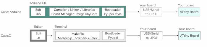
-
Download toolchain from microchip website. In my case, get
AVR 8-bit Toolchain 3.6.2 - Mac OS X 64-bit. -
Download ATtiny_DFP atpack from Atmel ATtiny Series Device Support packs. In my case, get
Atmel ATtiny Series Device Support (1.9.337). Change the file extention from .atpack to .zip, then unzip it.
Change make file as below, PACK and PORT needs to correct your pass.
PROJECT=hello.t3216.blink
SOURCES=$(PROJECT).c
DEVICE = tiny3216
MMCU=at$(DEVICE)
F_CPU = 20000000
PACK = ~/Desktop/Atmel.ATtiny_DFP.1.9.337
PORT = /dev/cu.usbserial-D307OEPH
BAUD = 57600

CFLAGS=-mmcu=$(MMCU) -Wall -Os -DF_CPU=$(F_CPU)

$(PROJECT).hex: $(PROJECT).out
    avr-objcopy -O ihex $(PROJECT).out $(PROJECT).hex;\
    avr-size --mcu=$(MMCU) --format=avr $(PROJECT).out

$(PROJECT).out: $(SOURCES)
    ~/Documents/avr8-gnu-toolchain-darwin_x86_64/bin/avr-gcc $(CFLAGS) -I./ -I $(PACK)/include -B $(PACK)/gcc/dev/$(MMCU) -o $(PROJECT).out $(SOURCES)

pyupdi: $(PROJECT).hex
    pyupdi -d $(DEVICE) -c $(PORT) -b $(BAUD) -v -f $(PROJECT).hex
Open terminal, and run make -f hello.t3216.blink.make, and run make -f hello.t3216.blink.make pyupdi to program.
7. Links to Codes
- M5 Stack practice
- LED and SWITCH / ino
- hello.t3216.blink.c
- hello.t3216.blink.hex
- hello.t3216.blink.make