How to make (almost) anything.
Week 06. Electronics Design
Work done in the Lab under the guidance of my remote Instructor to accomplish the weekly assignments.
This week I made a new board: completed the logical scheme, drew the board and the pads for its components, cut it and soldered it.
My weekly schedule:
| Wednesday, March 3 | Thursday, March 4 | Friday, March 5 | Saturday, March 6 | Sunday, March 7 | Monday, March 8 | Tuesday, March 9 |
| Global class | Global class review | Microcontroller circuit board test | Board design on Eagle | Board design on Eagle |
Board design on Eagle Board milling |
Board soldering Upload documentation |
Group assignment
This week we used the test equipment in our lab to observe the operation of a microcontroller circuit board, you can read it there.
Reading, a lot.
This week again I felt that I was not going to achieve it, everything that involves electronics uses terms that I do not know and at first they sound really scary but by reading the data sheets carefully I could understand a lot of fundamental things, in a few words this was a theoretical week.
To avoid making many mistakes I stuck to the tutorial available in the FabAcademy documents so I did all the drawing work in Eagle as explained there.
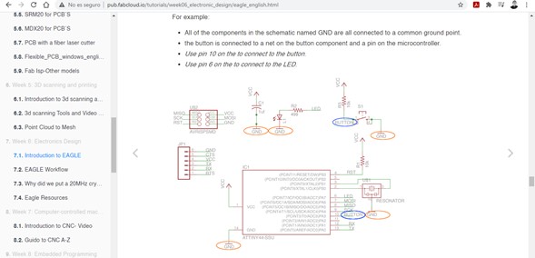
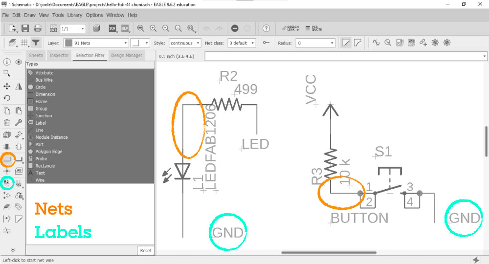
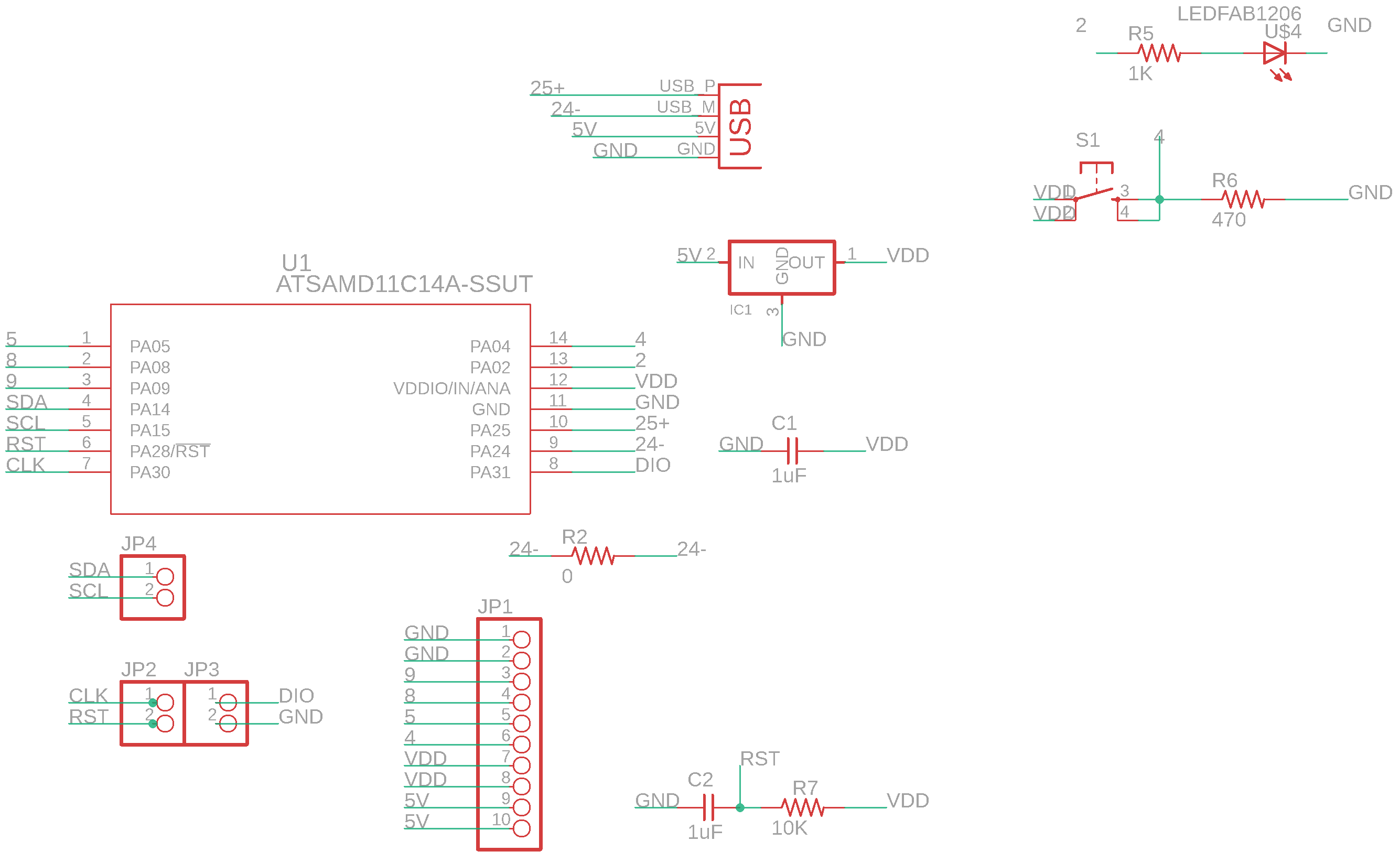
The document includes a file with a diagram to which some components must be added, at first glance I did not understand anything but analyzing it carefully I realized that it is a graphic representation of a circuit even without its parts being physically connected (the relationships were established by names rather than crossing lines).
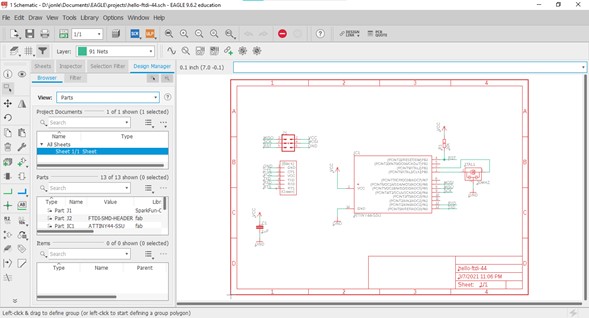
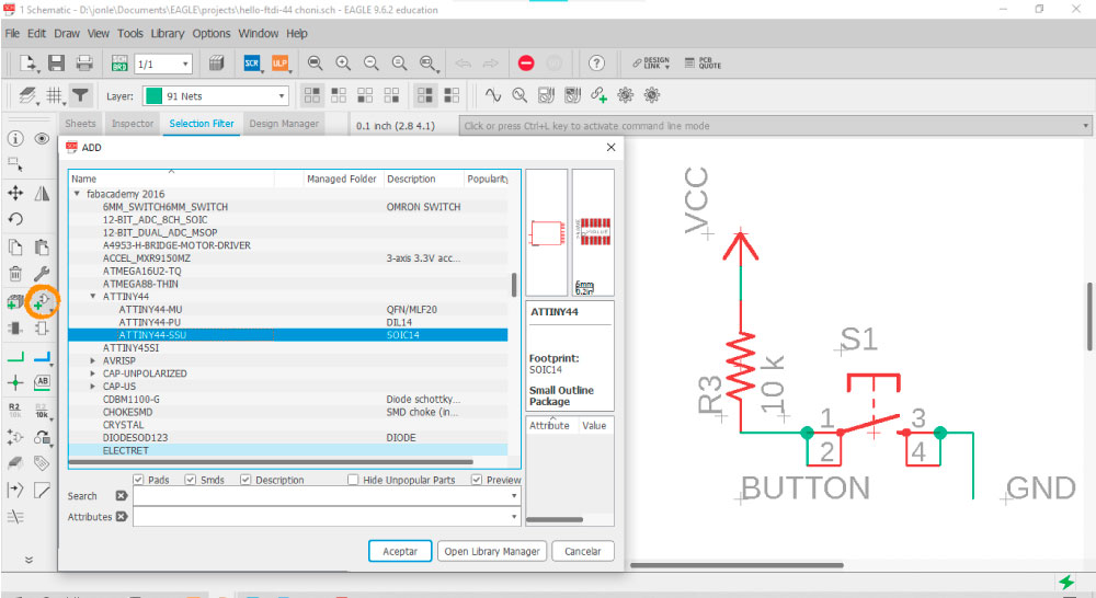
The file already has the most important components, to add more it is necessary to install the library that includes the components present in the inventory of each FabLab. Once the library is installed, all you have to do is click on the "Add part" button and search for the desired component in the list.
Once the necessary components have been added they must be connected to create the circuit, this can be done by drawing “Nets” that literally make connections between different parts or by just adding labels to avoid crossing many lines.
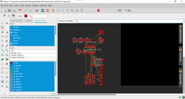
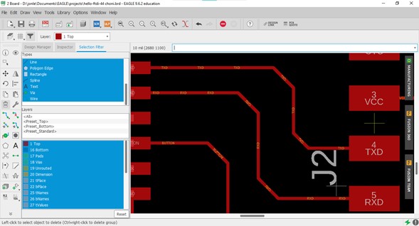
To generate the board file just click on the Switch to board button. The program delivers all the silhouettes of the components and these are connected by lines according to what has been indicated in the diagram. In this section the physical arrangement of the elements must be carried out, taking care that there is enough space between the tracks to prevent them from connecting together.
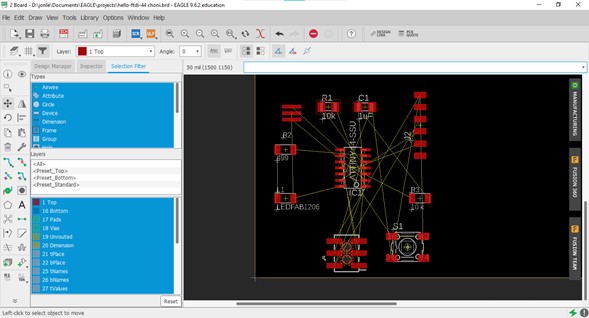
To make the physical connections you have to click on the Route Airwire button and join with these lines the components that are already connected with a thin yellow line.
Luis suggested that I should avoid 90 ° angles on the board traces because the movement of the cutter can tear the copper off in such tight intersections, although there are parts where it is unavoidable due to the position of the components or the intersection of two tracks.
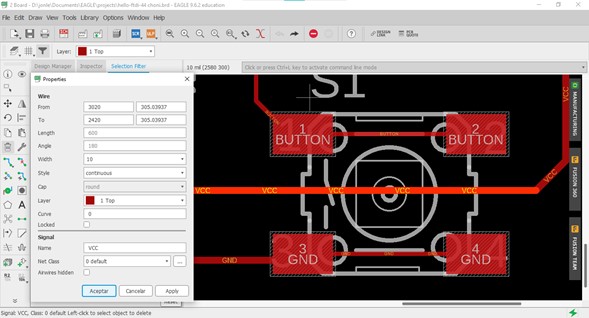
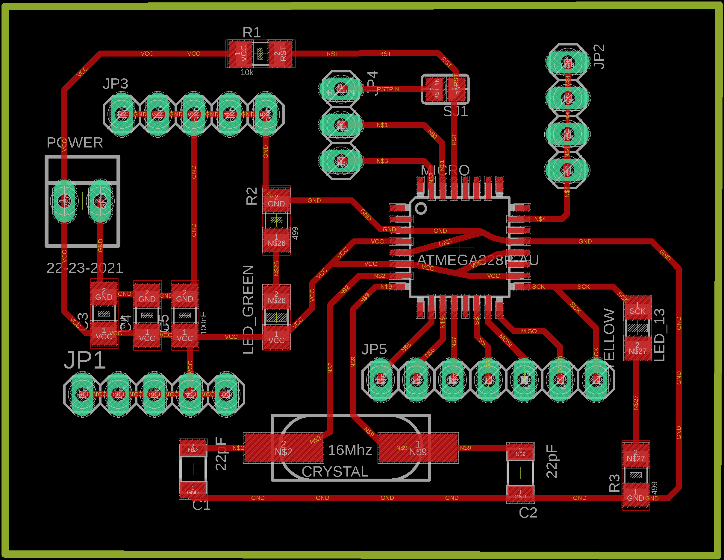
He also recommended that I should thicken the GND and VCC lines to 10 as there is more energy flowing out there.
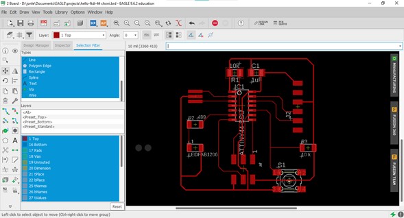
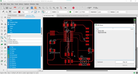
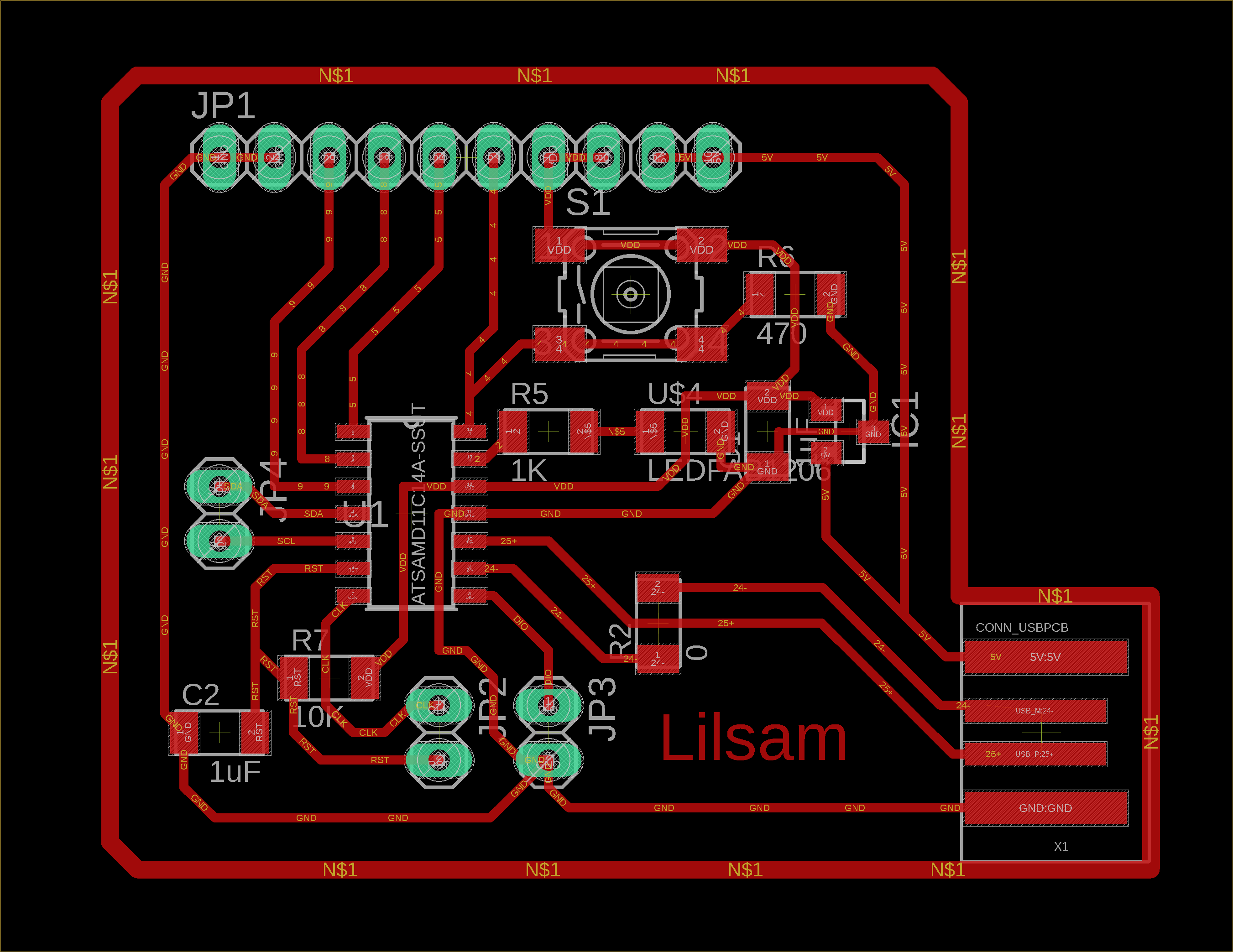
Finally the drawing was this:
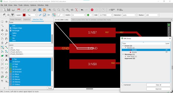
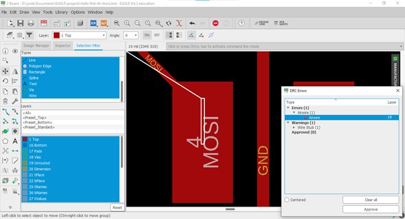
Once the position of the elements on the board is ready, a review of the design rules must be carried out in order to find logical or physical errors. To do this I tried to load the DRC file of the Academy but it showed me the following error:
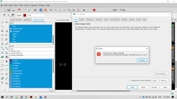
I assumed that the default DRC file that comes with the program could be used to check my errors and the only ones that appeared were connection segments that were not completely connected to the component, so correcting them was very easy.
It is satisfying to see an error-free window.
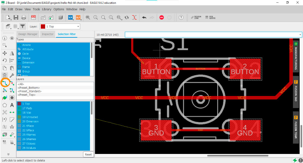
Before exporting the board I turned off the layers that were not necessary leaving only the pads and tracks. As I did not know the exact name of the layers I needed, I filtered the ones that were in use and turned on one by one to see what each one contained. The most important information for me was in the Top and Dimension layers.
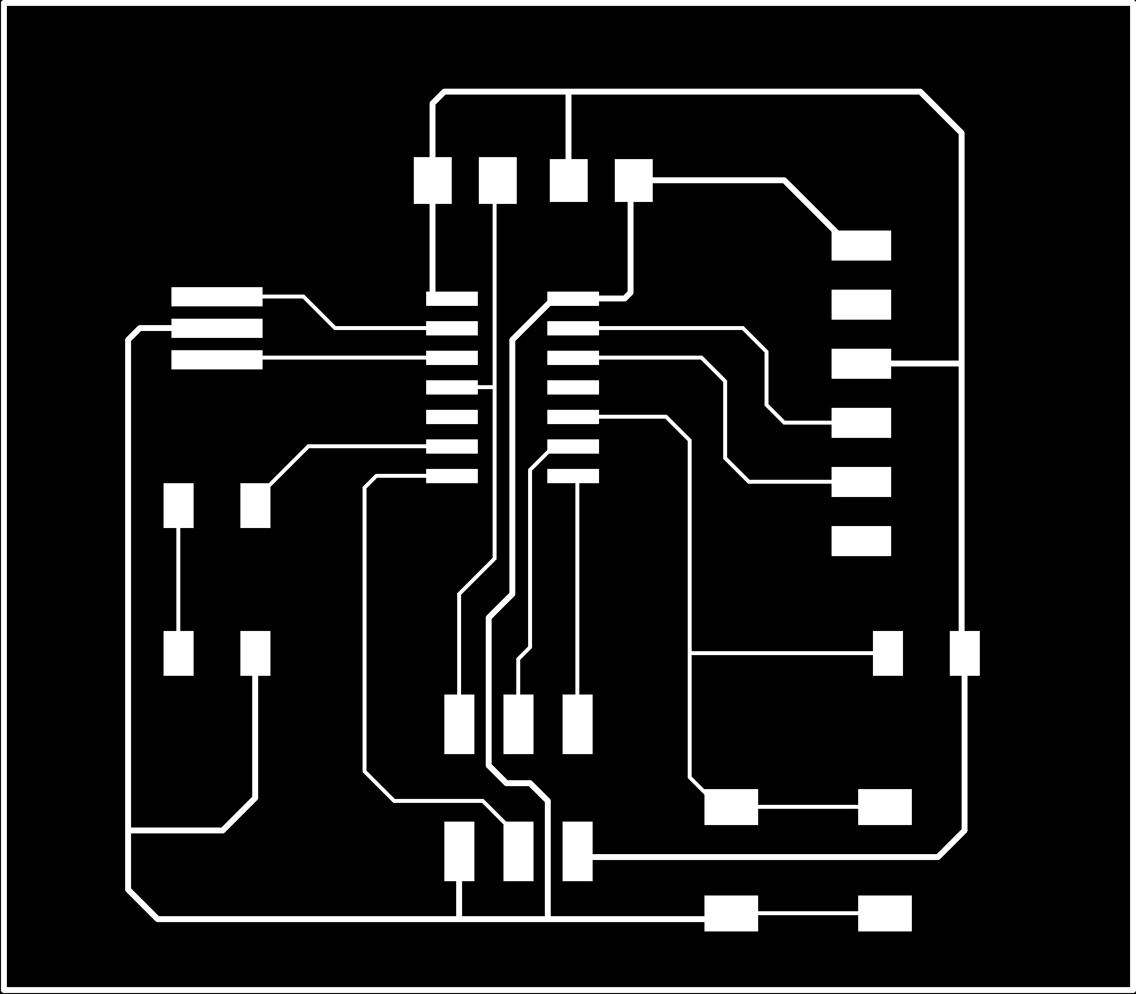
To export, click on File / Export. It is important to have a good resolution so that the engraving does not present deficiencies because the image has very few pixels, I exported using Monochrome and 1200 DPI. The same process must be done first with the traces (Top layer) and then with the cut perimeter (Dimension).
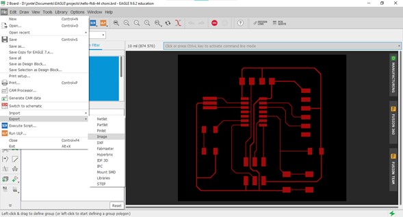
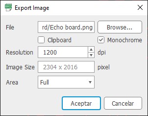
This is the exported image:
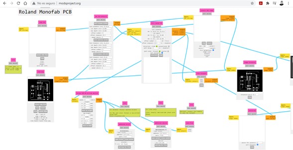
I took it into Mods to make the .RML file to cut it on the Roland SRM-20.
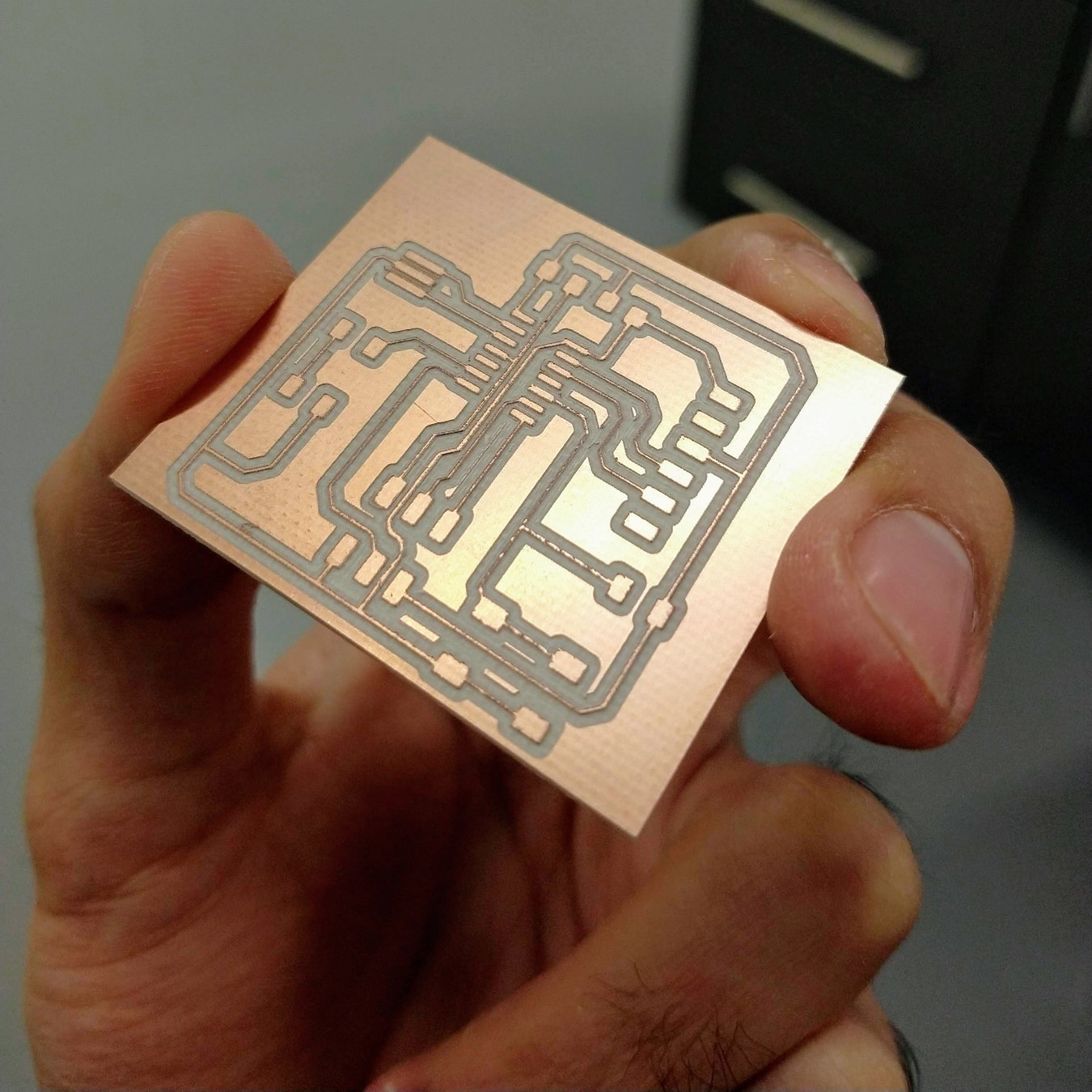
The cut was successful, all the mistakes I made in Electronics production week turned into learnings.
To solder, I started with the most complicated part: the ATtiny44 processor, having so many thin legs it would be more difficult after installing the rest of the components (I anticipated this situation anyway and leaving some space between the components, this time I didn't want unnecessary complications) .
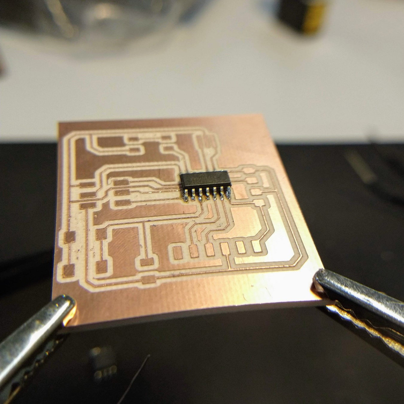
Practice makes perfect, this board was much easier for me to solder than the previous ones, I think it is a matter of practicing and controlling your breathing to avoid tremors in your hands.
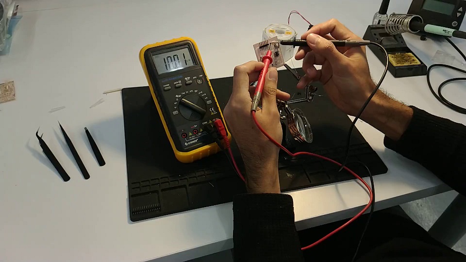
To check the board I used a multimeter: with the option to check continuity I verified that the circuit connections were in good condition and then I measured the capacity of the resistors.
Everything seemed to be fine but when uploading the sketch from Arduino IDE using the FabISP the LED did not turn on (and Arduino did not show any error).
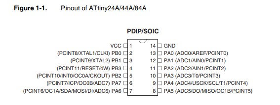
We tested with different pins since the pinout has different numbers: (PCINT7 / ICP / OC0B / ADC7) PA7, but the only thing we achieved was that the FabISP LED was the one that flashed (because in thas case the code was correctly programmed in the Echo board processor, the voltage flowed through the SCK pin (4) thus feeding the programmer's LED).
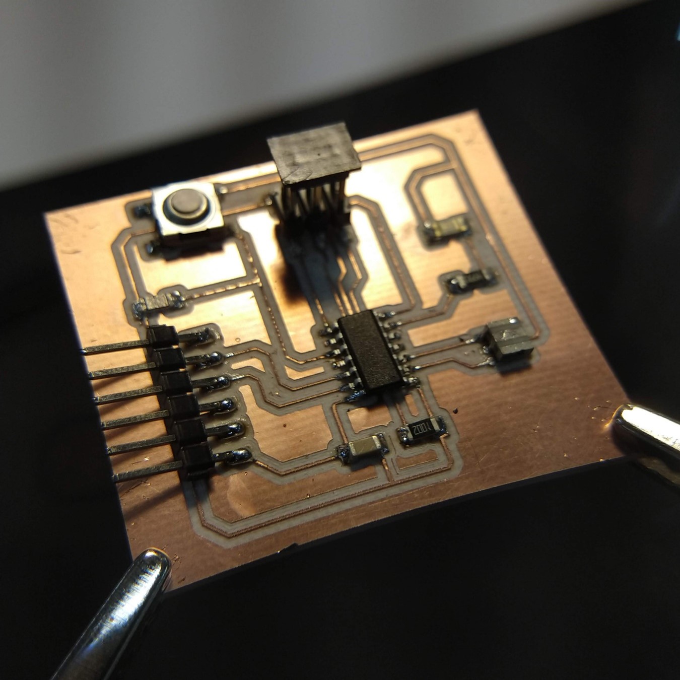
Luis helped me with the debugging process, first he checked that the wiring connections were correct and then he checked the continuity of the entire circuit using a multimeter, he found a detail that I missed in the soldering of the resistor that goes next to the LED . After soldering it correctly we did the test and the board worked as it should.
To check that the button also worked I uploaded the Button sketch from Arduino IDE examples.
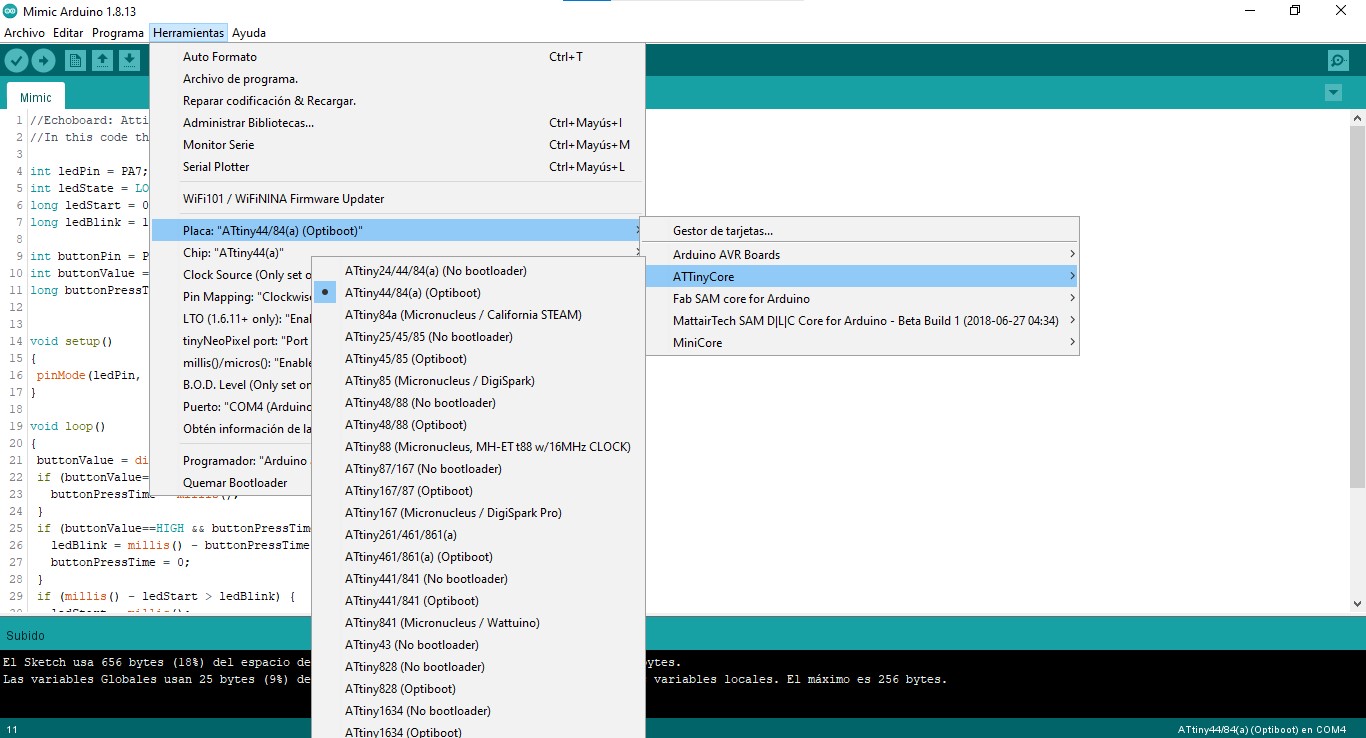
And finally to check the clock frequency I uploaded "Mimic", an sketch using millis: the processor takes note of the time the button is pressed and uses it as a reference for the blink intervals.
SAMD11c
To update this assignment using new generation processors I used a SAMD11c and Adrián Torres Samdino's design to make a simpler board by removing the 9v output and converting the I2C pins to conventional digital pins.
The goal was to update my assignment and although I could have made a simple Hello world board I preferred to spend a little more time on it and have a board that I could take advantage of to update some other assignments that involve inputs, outputs and serial communication, so in the end I finished with a board with several digital and analog pins and a USB interface to connect it directly to the computer.
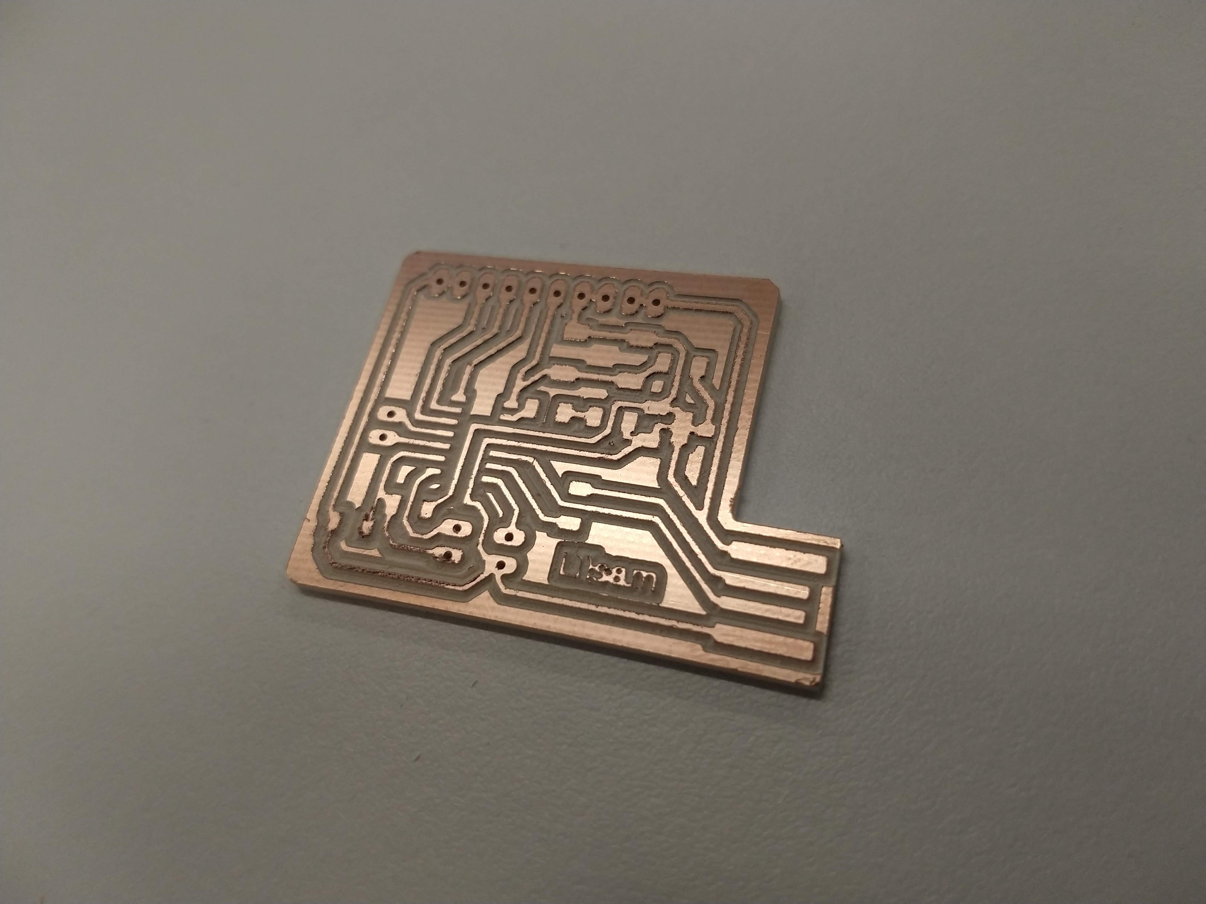
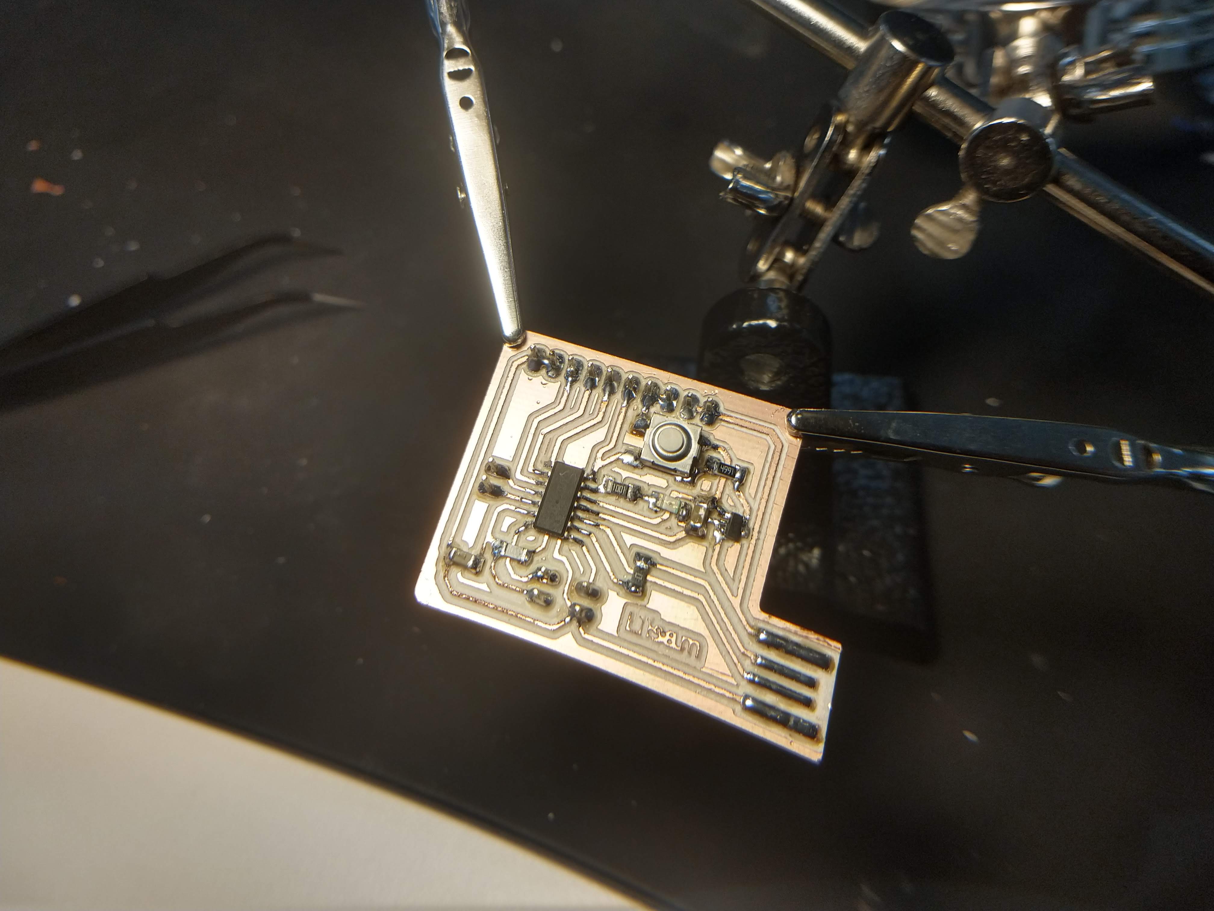
I cut it on the Roland.
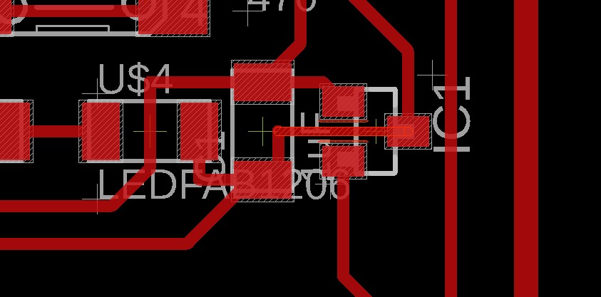
When I saw the pads for the 3.3v regulator I thought it would be quite difficult to solder since it was likely to leave some solder residue between the pad and the regulator terminals. I decided to take the risk of soldering a board and, if it was too complicated, to modify the design and use a 0 ohm resistor as a jumper. In cases like these it is important to solder the components in order of difficulty, since the most likely mistakes are made at the beginning, and not when you have already soldered a lot of components (and no, removing components without damaging the tracks is not as easy as it sounds). With patience I was able to solder the regulator so I did not modify the design, but it is a point to consider for future occasions.
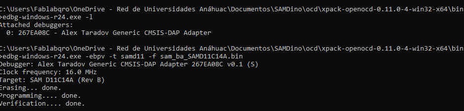
After soldering the components I burned the bootloader with EDBG and then loaded the sketches directly from Arduino IDE.
Final project update
Daniele Ingrassia created the Satshakit, a board very similar to the Arduino UNO that can be manufactured with the components and machines available at any Fablab, which is why it is widely accepted within the network. I read all the documentation online and took it as inspiration to create my own board.
v4. I hope this is the final version.
Files
You can download the Echo board Eagle project files here.
You can download the RML files here.
You can download the PNG images here.
You can download the INO files here: Blink, Button, Mimic.
You can download the Eagle files for my SAMD11c board here: board, schematic.
You can download the Eagle files for my ATmega328P board here.
|
For this assignment I:
|