How to make (almost) anything.
Electronics
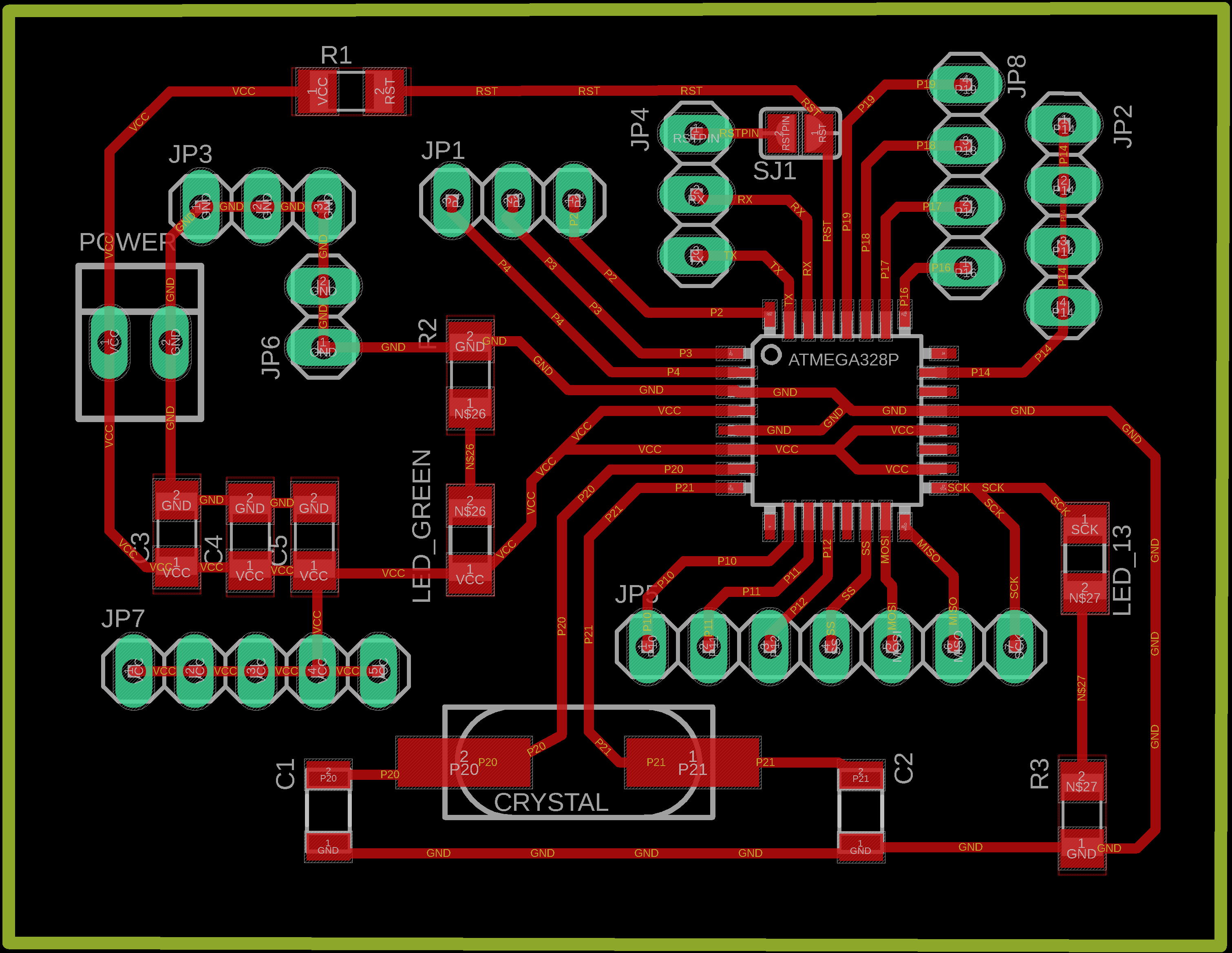
The main board for this project is based on the Satshakit created by Daniele Ingrassia, just with a few modifications on some pins, it's a board very similar to the Arduino UNO that can be made with the components and machines available at any Fablab, which is why it is widely accepted within the network. I read all the documentation online and took it as inspiration to create my own board.

|
Downloads |
I'm using an ATmega328P because it has a lot of memory and pins for inputs and outputs (that were helpful with some of my assignments) but mainly because of its compatibility with the entire Arduino ecosystem as it is recognized as an Arduino UNO within the IDE.
This can be programmed using my FabTinyISP or any Arduino Board.
This board involved several redesigns over time to better meet the needs I had for this project.
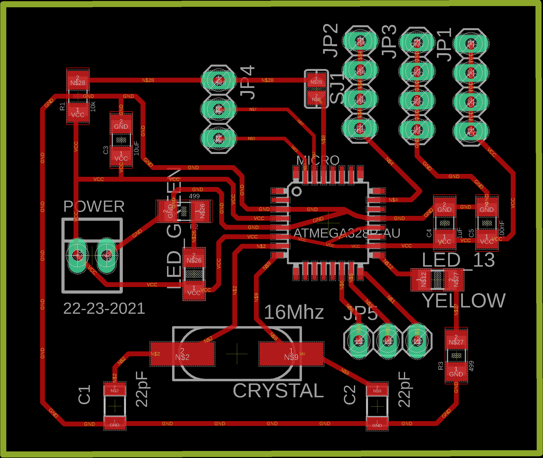
v1. In my attempt to make a simple board I removed more pins than I needed.
v2. On this one by mistake I disconnected the SCK pin, so it can't be programmed. And no, I didn't realize it until I had all the components soldered 😭 .
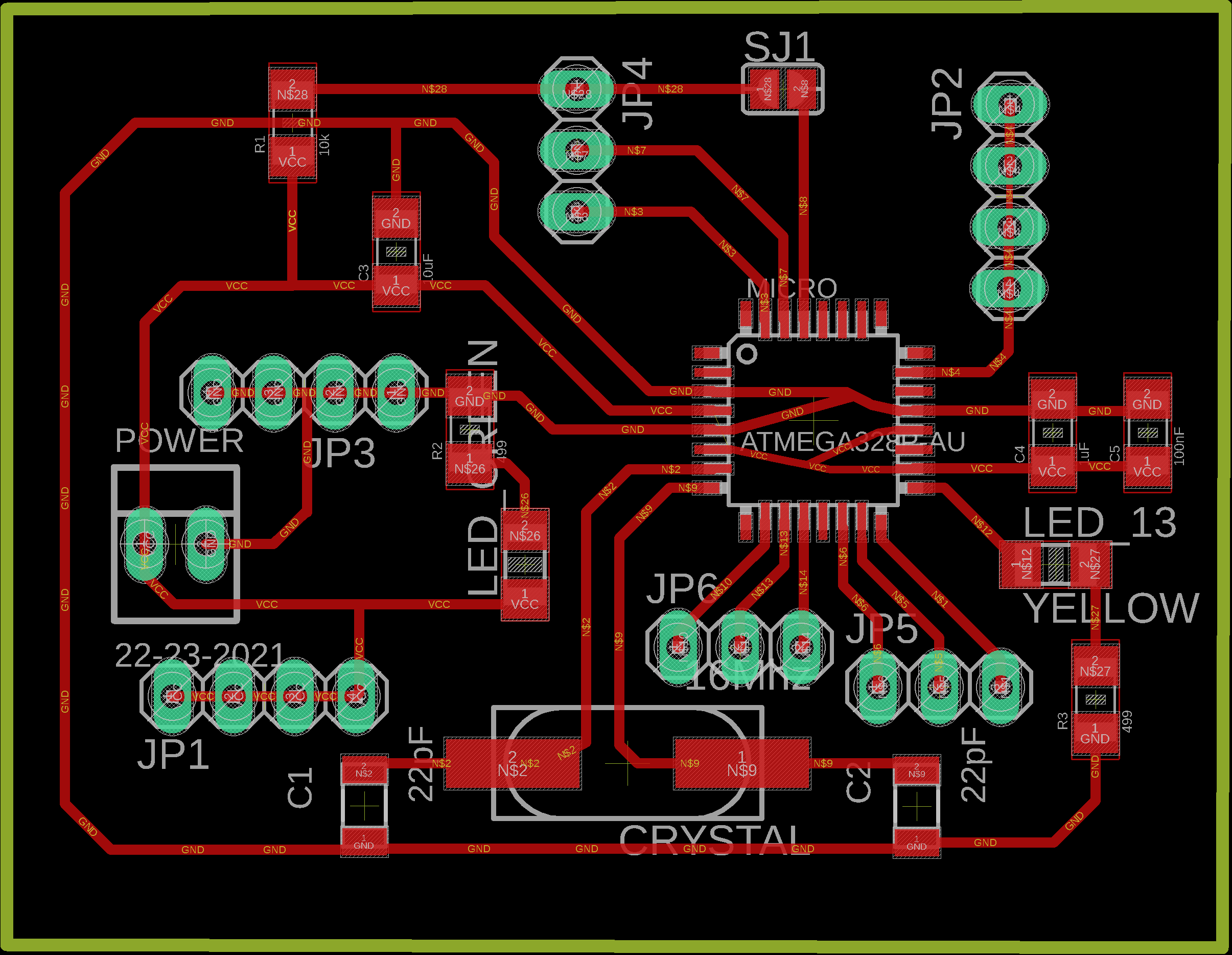
v3. This actually works, but to use it with a button I needed another set of VCC and GND pins so I designed version 4. Before cutting and soldering it I changed my mind about the input device (instead of using a button I incorporated a capacitive sensor that only required two free pins) and everything was working fine with this board, so until now I haven't build the corrected version of this version. This one has every pin I need for this project (and a few others which helped me complete other assignments like Networking and Communications).
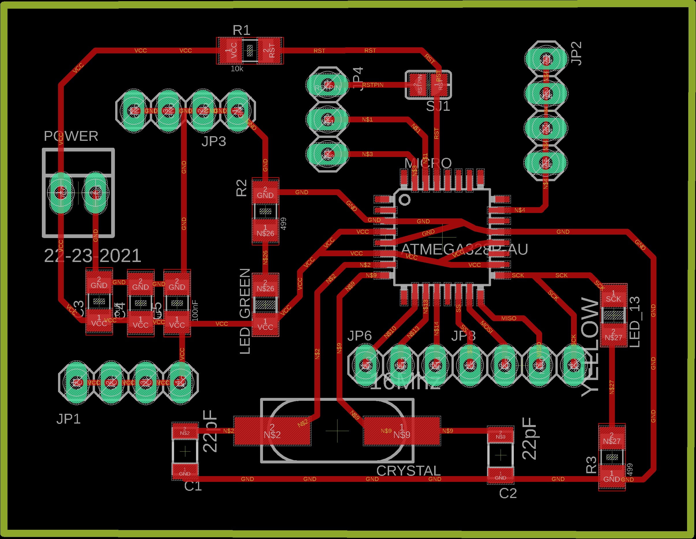
v4. The final version, this one has more pins enabled. In case of using a button or some other input device that requires GND and VCC, this version does have enough pins to power it (5 sets, when using a button I needed 4 outputs and 1 input).
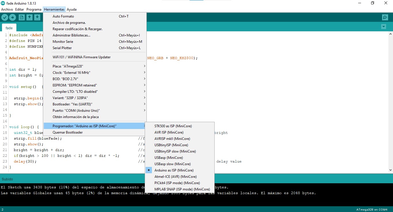
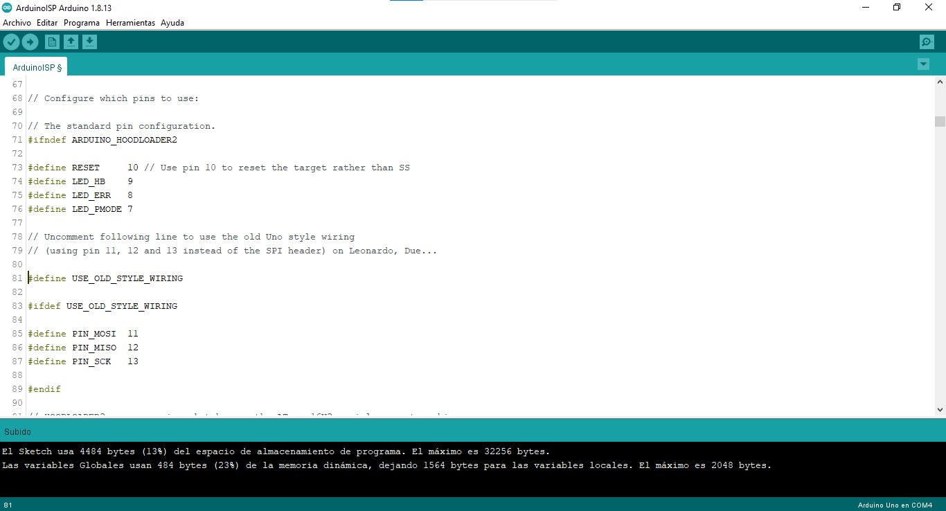
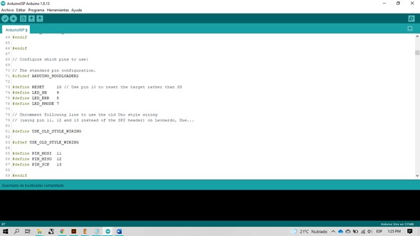
I burned the bootloader using an Arduino Uno as ISP. I made the connections as indicated in the ArduinoISP sketch in OLD_STYLE_WIRING mode: RESET (PIN 10), MOSI (PIN 11), MISO (PIN 12), SCK (PIN 13).
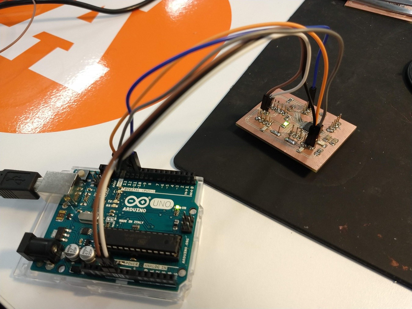
The test sketch was a Blink from Arduino IDE examples, uploaded with an Arduino Uno as a programmer.
Input device
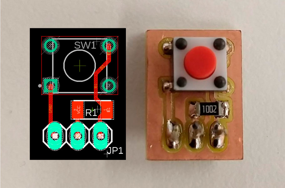
For the first version this project used a button that toggles between functions or turns it off.
|
Downloads |
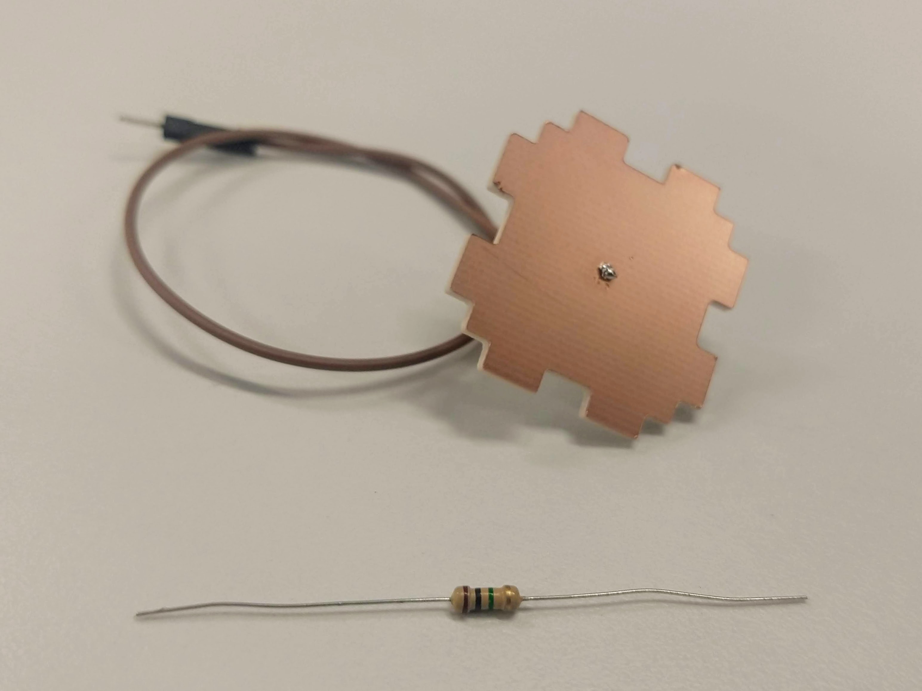
For the next spiral in the development of my project, I tried to improve the user experience, so I decided to change the input device: instead of pressing a button, gently touch a capacitive sensor.
Just using a copper board and a 1 megohm resistor that breaks communication between two pins you can switch between lighting functions.
Output device
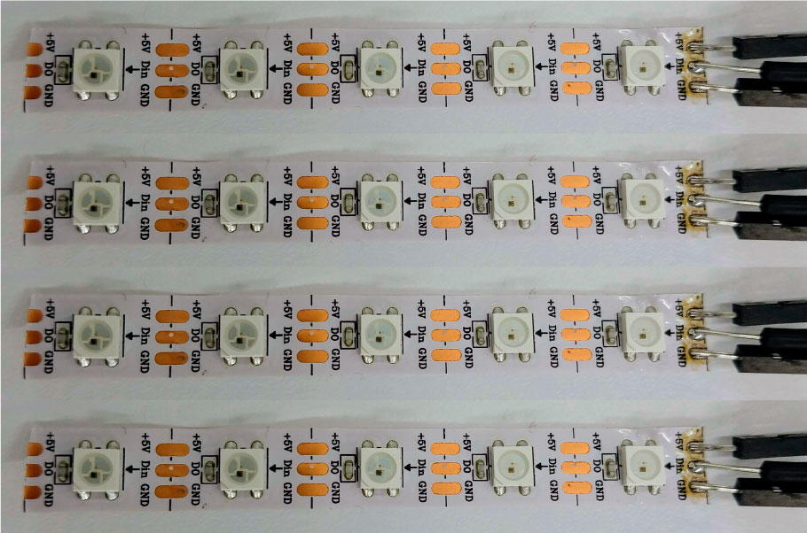
As output devices, this project uses four WS2812 LED stripes.
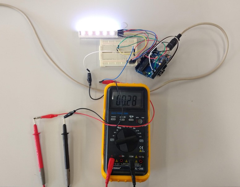
On my program the individual consumption of the LEDs at the brightness level that I am using is 28 mA, for the 20 pieces I need at least 560 mA so I'm using a 5v 1A power supply.
Board + Input + Output
System integration
The final device has the board inside the printed base, the LEDs inside the acrylic box and the capacitive sensor on the top.