The Process
We started the process of creating our machines all together at FabLab Barcelona. We wanted to do something that was collaborative, fun, and allowed us to interact between the different teams. To achieve this, we thought of a game that would allow us to include all the characteristics of a machine and that fulfilled all the requirements of the assignment.
We are 3 teams of awesome machines from FabLab Barcelona that create machines with mechanisms to press buttons. Each machine has its own button and the game is to avoid another machine from pressing your button.
The machines are remotely controlled and have 3 stepper motors. two of which control the wheels and the third controls the tool. Each team developed its own tool. Ours created the Slapper machine.
- Design a machine that includes mechanism + actuation + automation
- Build the mechanical parts and operate it manually.
- Actuate and automate our machine.
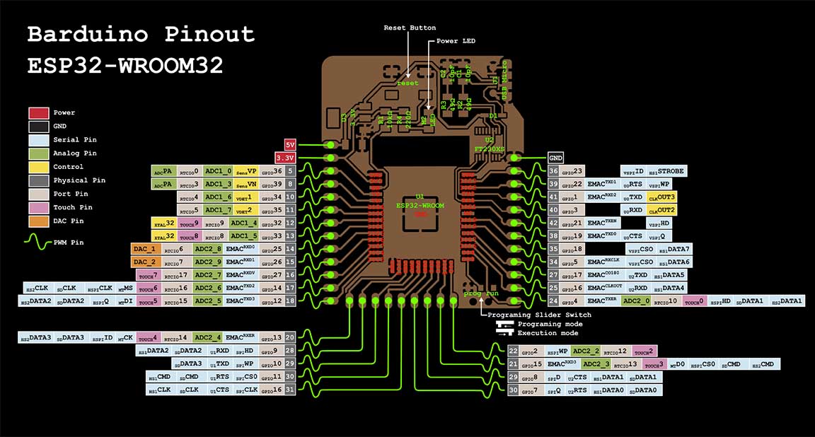
We started working on a core structure that was going to be the base for all the machines. After some consideration we decided to use the Barduino board (link here) to develop our machines.
We divided the tasks:
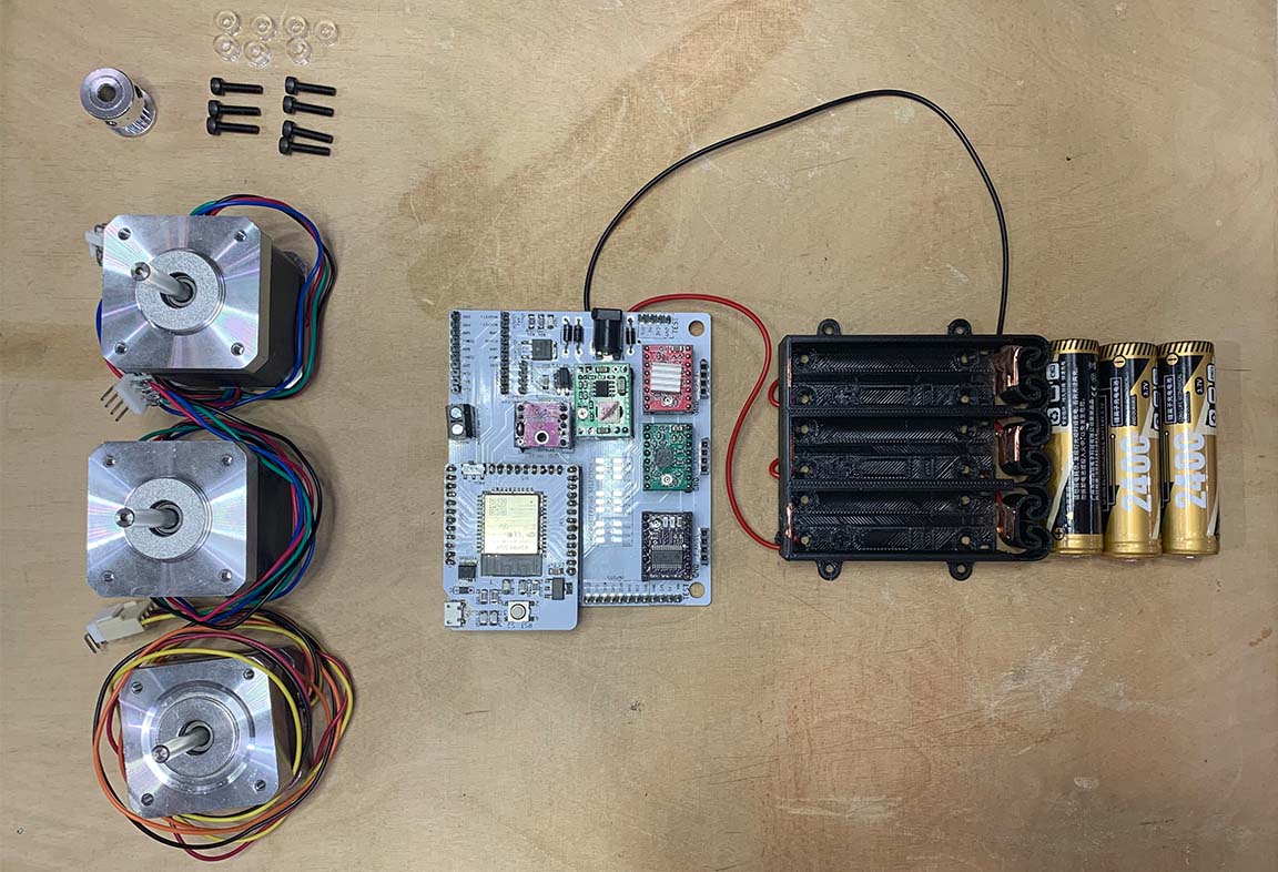
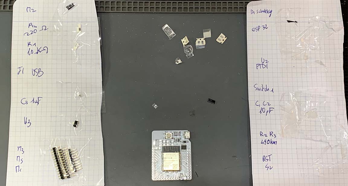
- Defining and selecting the components.
- Soldering the Barduinos.
- Researching on how to use the code (link here).
- Designing and 3D printing the wheels.
- Designing and laser-cutting the base.
- Designing and 3D printing the base for the motors.
- Designing and 3D printing the base for the base for the buttons.
- Defining and debugging the basic code that we needed to use to make the wheels work.
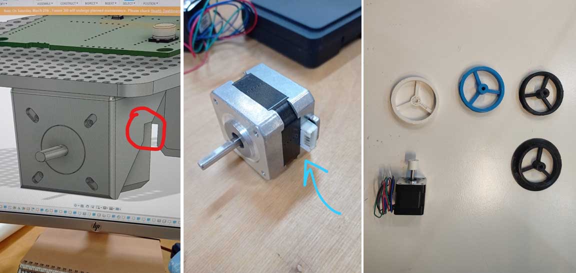
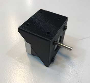
Motor and the 3D printed base
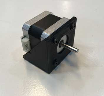
The motor was touching the head of the screws.
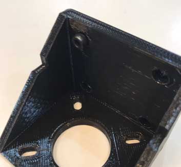
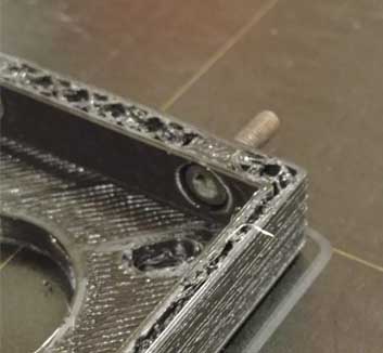
So, Marc updated the model to fix this and printed them usins Onyx and the Markforged Mark two printer.
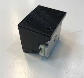
Battery case
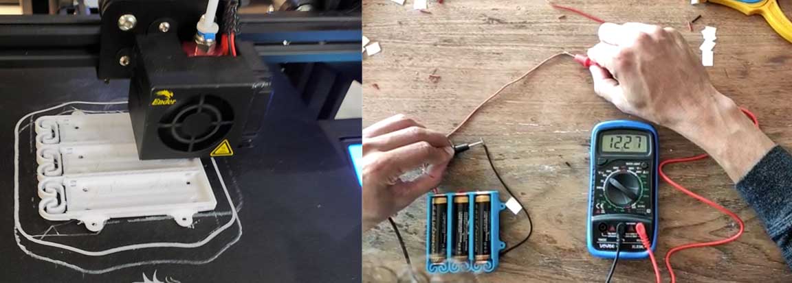
Meanwhile, Gerardo was printing and testing the battery case.
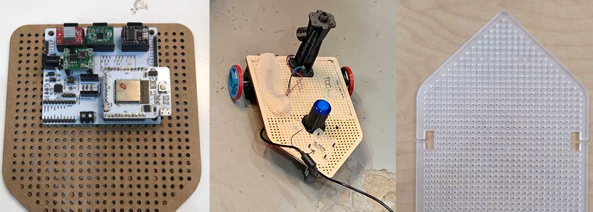
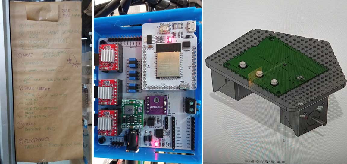
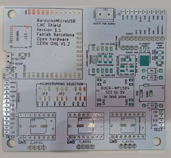
Assembling the Barduino board and shield
We followed this documentation to assemble the Barduino and the shield:
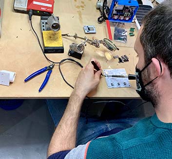
The most complex parts were the FTDI and the micro USB connector. It took us a long time to get all the plates to work properly. In fact ours had quite a few problems. The solder was not right. It was cold-welded, which made it seem sometimes well connected and sometimes not. We had to re-solder it to make it work properly because when removing and inserting the USB it stopped working properly.
Awesome machine 3 documented Embedded programming and Electronics process:
Tarek used this web that Edu shared with us to define the code for the steppers
After the core part was finished, we divided the tasks between the members of Awesome Machine 3 team to get the Slapper running.
Coding and debugging
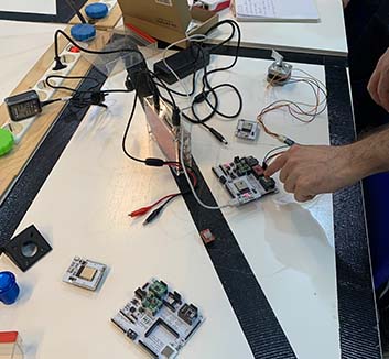
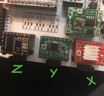
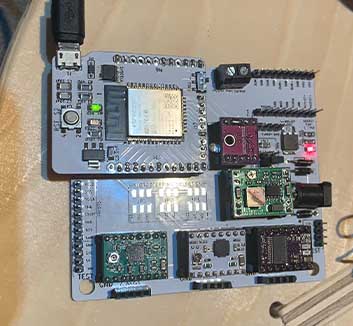
After the group process the result was a Barduino with the soldiers components for each group. 3 Drivers and 3 motors.The challenge was to be able to flash the board correctly and then check that the drivers worked fine.The code the group had made was designed so that the X motor and the Y motor would work and then each group code individually the function of their tool work.
Carla created an awesome documentation on how to flashe the board and set the motors with the drivers.
Resources
We follow all these that Carla stated on ther documentation to get our motors running:
- Download or Clone this repo: Clone me!
- Copy this two libraries from the libraries folder on the Firmware libraries folder to your Arduino Library folder. Mine is on Documents/Arduino/Libraries: ESP32SSDP and arduinoWebSockets
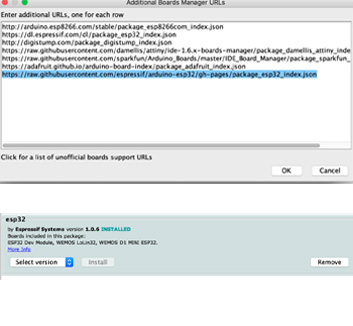
- Install Board Manader for ESP32 > Arduino > Preferences: Copy/paste this URL https://raw.githubusercontent.com/espressif/arduino-esp32/gh-pages/ package_esp32_index.json
- Install ESP32 Espressif on Board Manager
- Reading installations instructions from here: Instructions
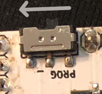
- Make sure that before you connect the board the switch is on programming mode.
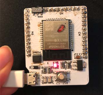
- Original Grbl documentation says to remove the barduino board from the shield to program the firmware to prevent any possible damage to the shield. Connect the board.
- Select board. ESP32 - dev Module.
- Change Partition scheme to Minimal SPIFFS
- Compile Firmware Arduino File - it will take a while depending on the machine.
- Upload the code.
- Disconnect the board.
- Change the switch to Execution Mode.
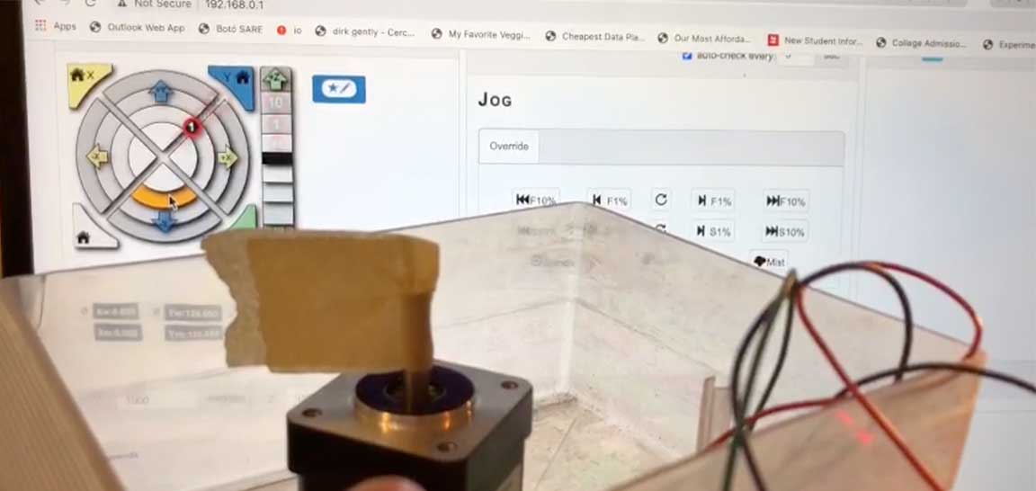
- Check for the ESP32 wifi connection. Select Wificonfig.h file to see the Wifi connection details. Using your browser of preference, access the IP in the code.
- We need to upload the index.html.gz file from the data folder that was on the firmware files. Thanks to Tue and David from 2020 Barcelona Fabacademy who had an awesome documentation. Tue & David Machine
Flashhing the board and setting the motors
After setting everything we uploaded this code to our Barduino using Arduino IDE
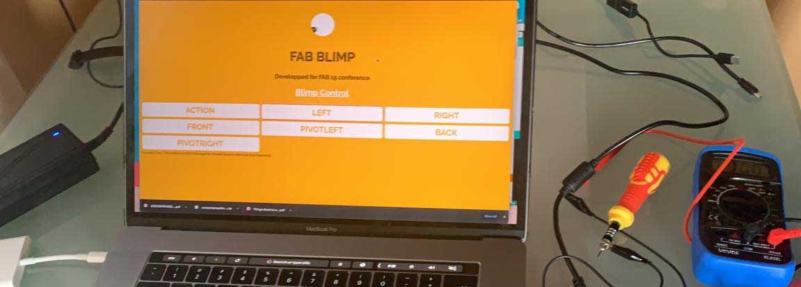
This was the code writen by Tarek and Adrien. We used it as a common base to get the motors running. The interface was more straight forward and easier to use.
First codeThen we continue following Carlas's steps to set the drivers.
- Check the Voltage of the Voltage regulator
- Now you can connect the Barduino to the driver board. Move the switch under the board to 5VUP before mounting the Barduino to the header pins.
- We watched this video to understand to understand how to set the drivers for the motors.
- Not all drivers have the same pinout orientation. Check for GND to match the shield.
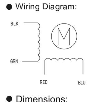
- For the NEMA 14- SY35ST36 —> The Voltage measured from the screw or VREF to GND needs to be around 500mV. Check Pololu
- When connecting the motors, make sure that the power supply is desconnected.

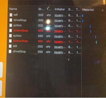
The code issue
This is the second code that we used. There were some minor bugs that we corrected like a capital leter on the command to stop the motor Z. Insted of actionStop it was writen ActionStop. But overall, it was working fine.
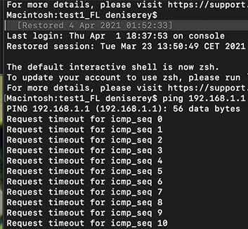
At that time we were connecting from the computer to the Barduino's FABLIMPEO wifi and we had the phone connected with a cable to the computer.
So, we continued working on the code to get motor Z working, the one that was going to activate the tool.
// == FRONT we wanted the tool to attack when moving on the front direction
if(action == "front"){
Serial.println("front_while");
digitalWrite(MOTOR_DIRECTION_RIGHT_DIR, LOW);
digitalWrite(MOTOR_DIRECTION_LEFT_DIR, HIGH);
digitalWrite(MOTOR_DIRECTION_RIGHT_STEP, HIGH);
digitalWrite(MOTOR_DIRECTION_LEFT_STEP, HIGH);
digitalWrite(MOTOR_TOOL_DIR, HIGH);
digitalWrite(MOTOR_TOOL_STEP, HIGH);
currenttime = millis();
while(millis()-currenttime < 0.3){

}
digitalWrite(MOTOR_DIRECTION_RIGHT_STEP, LOW);
digitalWrite(MOTOR_DIRECTION_LEFT_STEP, LOW);
digitalWrite(MOTOR_TOOL_STEP, LOW);
currenttime = millis();
while(millis()-currenttime < 0.3){

}
}
// == ACTION
if(action == "action"){
Serial.println("action");
digitalWrite(MOTOR_TOOL_DIR, HIGH);
digitalWrite(MOTOR_TOOL_STEP, HIGH);
currenttime = millis();
while(millis()-currenttime < 0.3){
}
digitalWrite(MOTOR_TOOL_STEP, LOW);
currenttime = millis();
while(millis()-currenttime < 0.3){
}
}
The FRONT command was working fine but for some reason we were not able to get ACTION command working.
We asked Edu for help and after a while we realized that we were missing a line of code:
server.on("/action", []() {
Serial.println("action");
action = "action";
server.send(200, "text/plain", "action");
});
What we did not realize is that in the process there was a request to download some libraries. By giving the computer internet through the phone, access was possible. When I disconnected the phone, the engines stopped working. Therefore, discussing this with Edu, he showed us that we should change the code so that it connects directly to the internet.
So, instead of this:
// ----------------
// Set your WiFi SSID and Password here
// ----------------
const char* ssid = "FABLIMPLEO";
const char* password = "12345678";


/* Put IP Address details */
IPAddress local_ip(192,168,1,1); //Ok


IPAddress gateway(192,168,1,1); //Ok
IPAddress subnet(255,255,255,0); //Ok

WebServer server(80); //Replaces ESP8266WebServer server(80);

const char *webpage =
#include "index.h"
;

void handleRoot() {
server.send(200, "text/html", webpage);
}
						WiFi.mode(WIFI_STA);
  WiFi.disconnect();
  delay(100);

  Serial.begin(115200);
  WiFi.begin(ssid, password);
  Serial.println("");

  // Wait for connection
  while (WiFi.status() != WL_CONNECTED) {
    delay(500);
    Serial.print(".");
  }
  Serial.println("");
  Serial.print("Connected to ");
  Serial.println(ssid);
  Serial.print("IP address: ");
  Serial.println(WiFi.localIP());

  if (MDNS.begin("WifiCar")) {
    Serial.println("MDNS Responder Started");
  }
We used this:
// ----------------
// Set your WiFi SSID and Password here
// ----------------
const char* ssid = "Iaac-Wifi";
const char* password = "enteriaac2013";

WebServer server(80); //Replaces ESP8266WebServer server(80);

const char *webpage =
#include "index.h"
	;

void handleRoot() {
	String message = "File Not Found\n\n";
	message += "URI: ";
	message += server.uri();
	message += "\nMethod: ";
	message += (server.method() == HTTP_GET) ? "GET" : "POST";
	message += "\nArguments: ";
	message += server.args();
	message += "\n";
	for (uint8_t i = 0; i < server.args(); i++) {
	message += " " + server.argName(i) + ": " + server.arg(i) + "\n";
	}
	server.send(200, "text/html", webpage);
}
Serial.begin(115200);

WiFi.softAP(ssid, password); //ok
WiFi.softAPConfig(local_ip, gateway, subnet); //ok
delay(100);
Ready to assemble