To keep track of how I got to the final phase of the program it is necessary by
looking at what I had done over the previous weeks - Output Devices and
Networking & Communications.
As I mentioned before, this project was developed gradually, starting from one, ending with the control of four motors, etc.,
also in the programming part - previously the control of one motor with the remote control was transformed into the control
of four motors.
    #include Servo.h

    #define IN_PIN 5
    #define ESC_PIN1 16
    #define ESC_PIN2 9
    #define ESC_PIN3 1
    #define ESC_PIN4 0

    //MODE_CH5 2      //PA6
    //YAW_CH4 8       //PB1
    //THROTTLE_CH3 5  //PB4
    //PITCH_CH2 4     //PB5
    //ROLL_CH1 3      //PA7

    int pwmIn;
    Servo esc1, esc2, esc3, esc4;

    void setup() {
    pinMode(IN_PIN, INPUT); // Read the channel PWM_IN signal from the receiver
    esc1.attach(ESC_PIN1,900,2100); // (pin, min pulse width, max pulse width in microseconds)
    esc2.attach(ESC_PIN2,900,2100); // (pin, min pulse width, max pulse width in microseconds)
    esc3.attach(ESC_PIN3,900,2100); // (pin, min pulse width, max pulse width in microseconds)
    esc4.attach(ESC_PIN4,900,2100); // (pin, min pulse width, max pulse width in microseconds)

    Serial.begin(115200);
    Serial.println("Initializing...");
    delay(1000);

    while(1){
    pwmIn = pulseIn(IN_PIN, HIGH);
    Serial.print("Receiver: ");
    Serial.println(pwmIn);

    int motorSpeed = map(pwmIn, 977, 1956, 0, 180);
    if (motorSpeed > 0){
    esc1.write(motorSpeed);
    Serial.print("Speed 1: ");
    Serial.println(esc1.read());

    esc2.write(motorSpeed);
    Serial.print("Speed 2: ");
    Serial.println(esc2.read());

    esc3.write(motorSpeed);
    Serial.print("Speed 3: ");
    Serial.println(esc3.read());

    esc4.write(motorSpeed);
    Serial.print("Speed 4: ");
    Serial.println(esc4.read());
    }
    }
    }
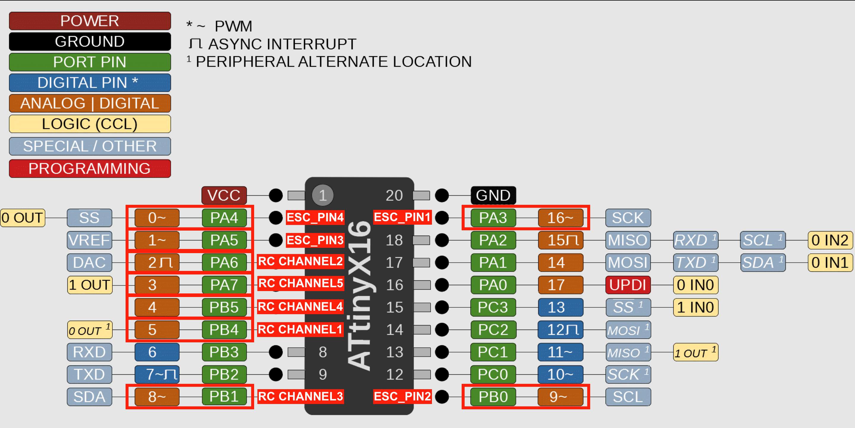
EXPLANATION OF PINS
As always for understanding microcontroller pins, I used
SpenceKonde. It should be remembered that the numbering of the microcontroller is different from that assigned to the variable in the Arduino.
The numbers in orange color (third column from left, fifth column from right) are those to be indicated on the Arduino. ESC pins present the symbol "~",
which in the case of ESC is very important when designing electronics, because ESC requires PWM functionality (this is confirmed by this symbol).
When developing a program, it is not necessary to add it to the variable.