
|

| Sukkur IBA University Merit, Quality, Excellence |
Week - 6
Electronic Design
Assignmentes of the Week
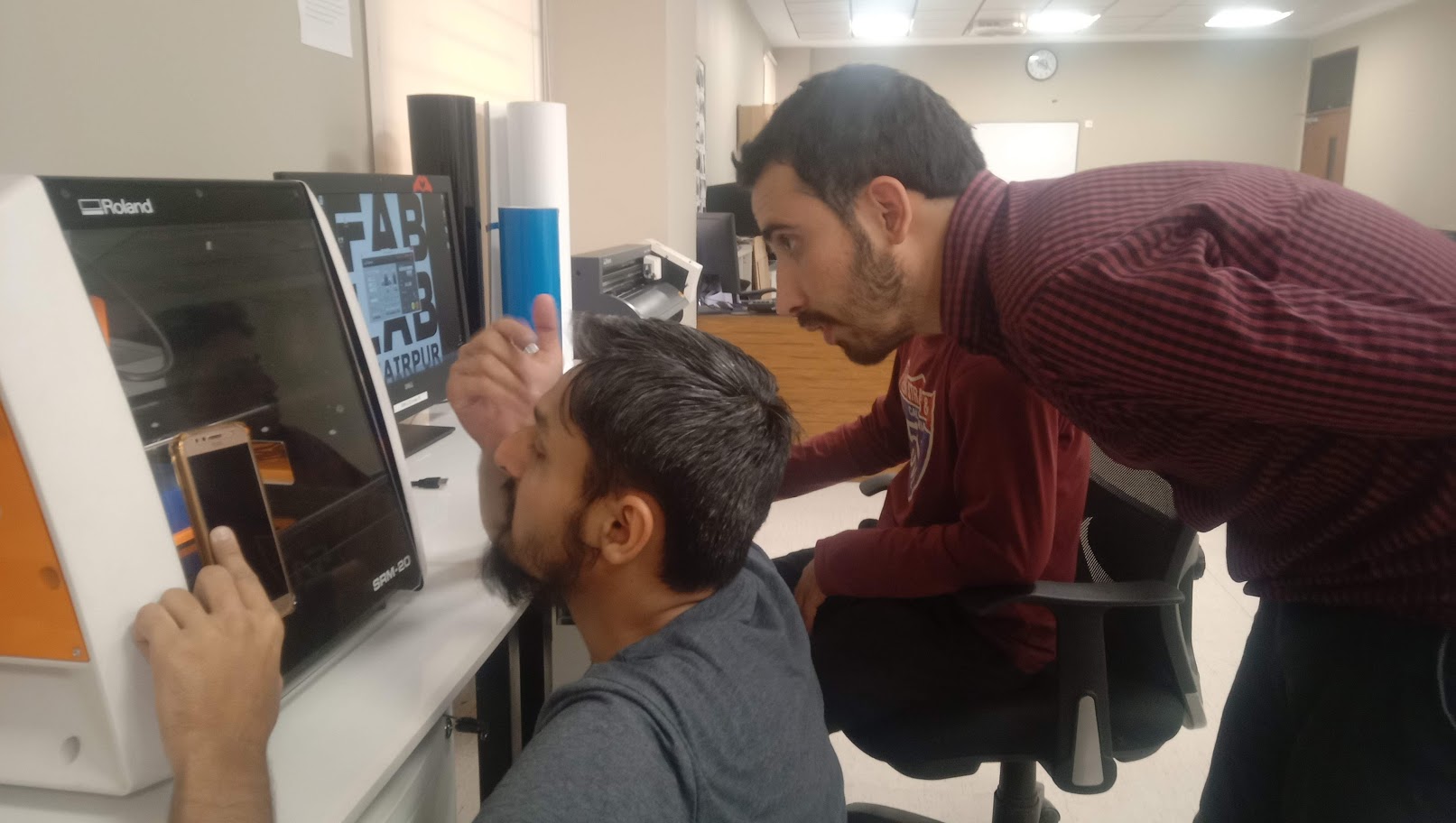
Group Assignment:Use the test equipment in your lab to observe the operation of a microcontroller circuit board.
Individual Assignment: Redraw the echo hello-world board, add (at least) a button and LED (with current-limiting resistor) check the design rules, make it, and test it extra credit: simulate its operation extra credit: render it.
Roland monoFab SRM-20

Here is the picture of SRM-20.
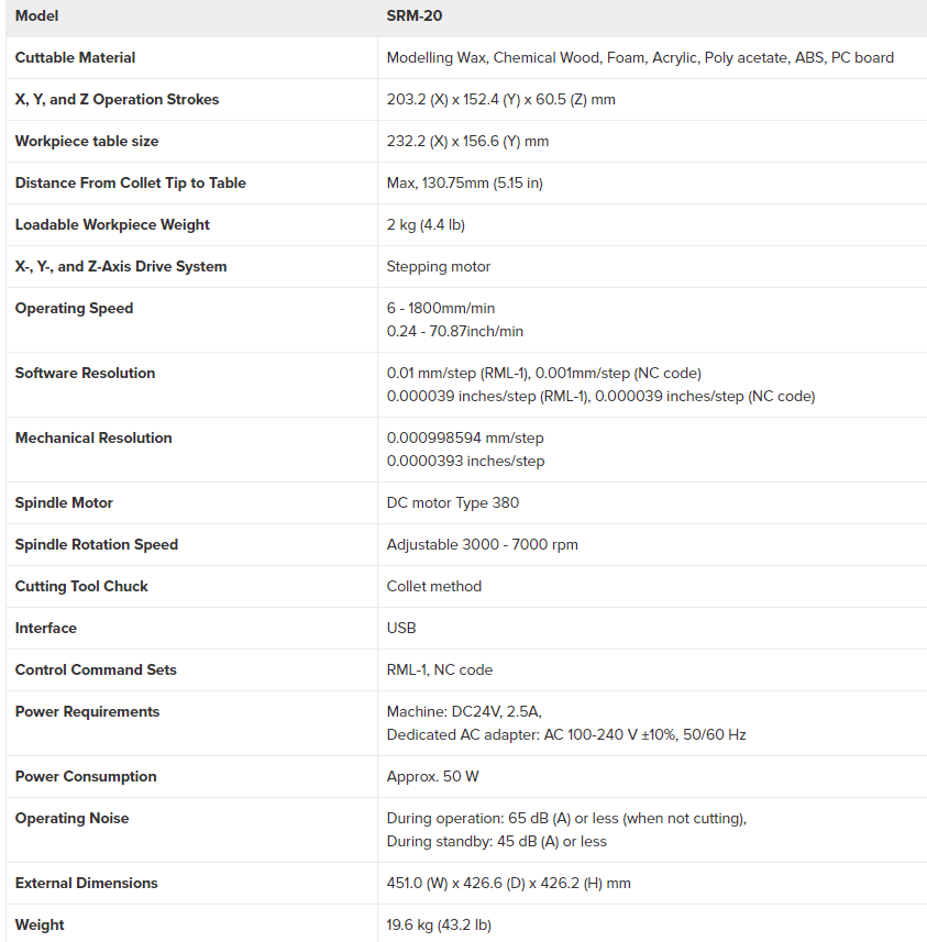
These are the specification of SRM-20.
Redraw the echo hello-world board
Download and install Software.
Download and install FAB libraries to get the list of components which are available in FABLAB.
Enlist the components which is seen in given hello-world board.
Redraw the echo hello-world board by adding input and output in it i.e, atleast one button and LED with current-limiting resistor.
Generate .rml files of traces and outer boundary of PCB.
Mill the PCB by giving .rml file to ROLAND SRM-20 milling machine.
Sold the components on PCB.
Test the board by burning program in it.
Maintainance of monoFab SRM-20
In our fabLab, we have Roland monoFab SRM-20 we are placeing FR1 PCB on bed and Also going to clean by using vaccum.
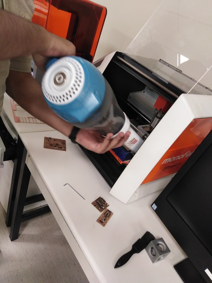
The vaccum pump is used to remove the waste.
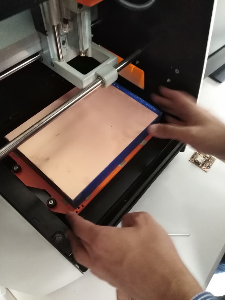
Placing the new PCB on the machine bed.
Now we are going to set the origin.
Individual Assignment
Redraw the echo hello-world board, add (at least) a button and LED (with current-limiting resistor) check the design rules, make it, and test it extra credit: simulate its operation extra credit: render it.
Eagle cs

Eagle is PCB designing software. Its a really powerful software with really great features. As post to manual designing, these software really help make life easy. The software is very easy to use and is merely drag and drop. The software can be download from Here
After the installation of the EAGLE the next target is to get fimilare with. Here is the very easy and usefull tutorial from which we can learn how to draw the circuit diagram in this software. So i used to design the with the helf of the This Tutorial Here
FAB Library
After installation of CadSoft EAGLE we need to include fab library in it, the library help us to get the proper PCB layout of the components in software which are available in FABLAB.The FAB library is downloadedfrom Here
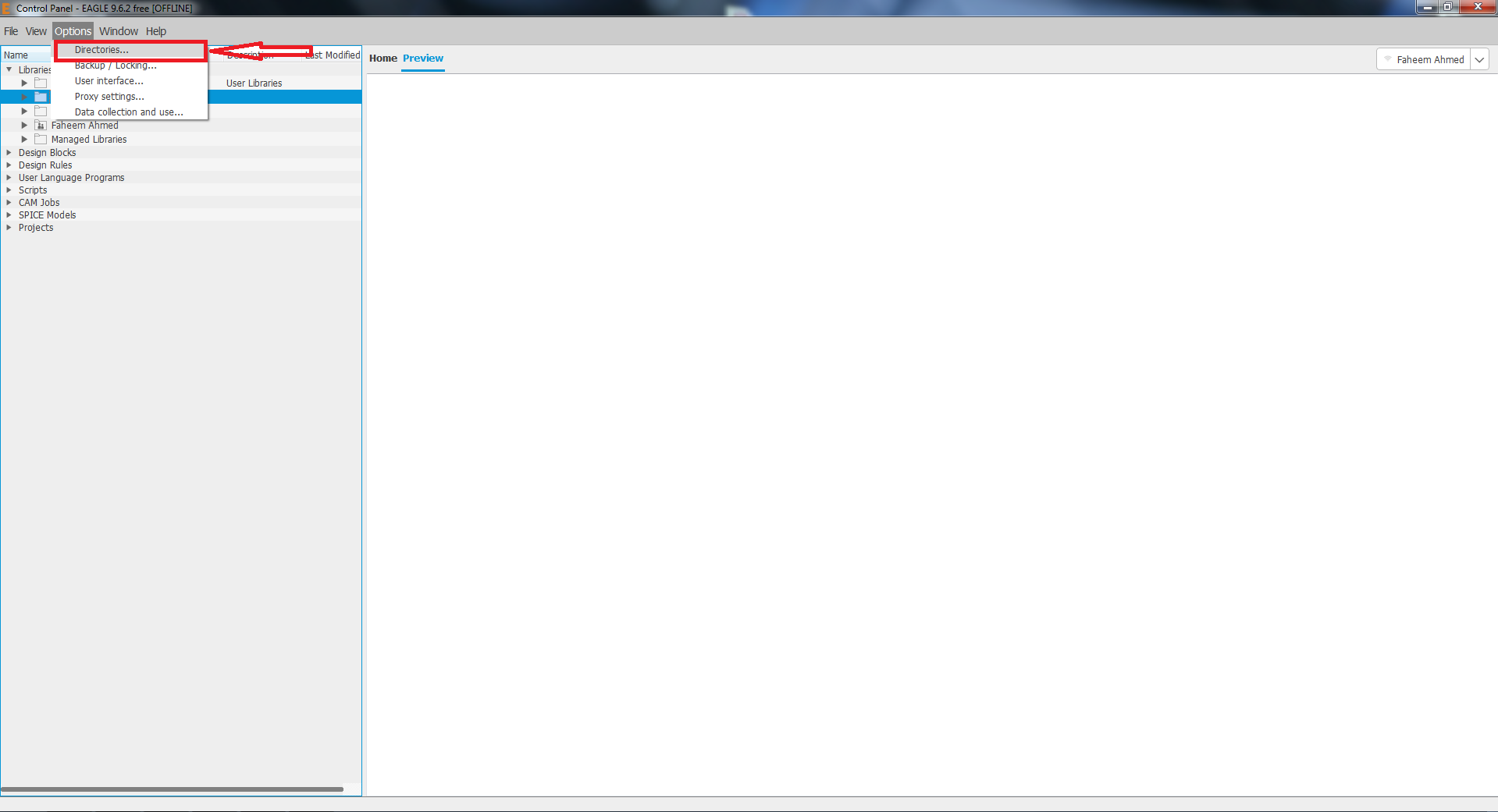
Go to options and Click on directries
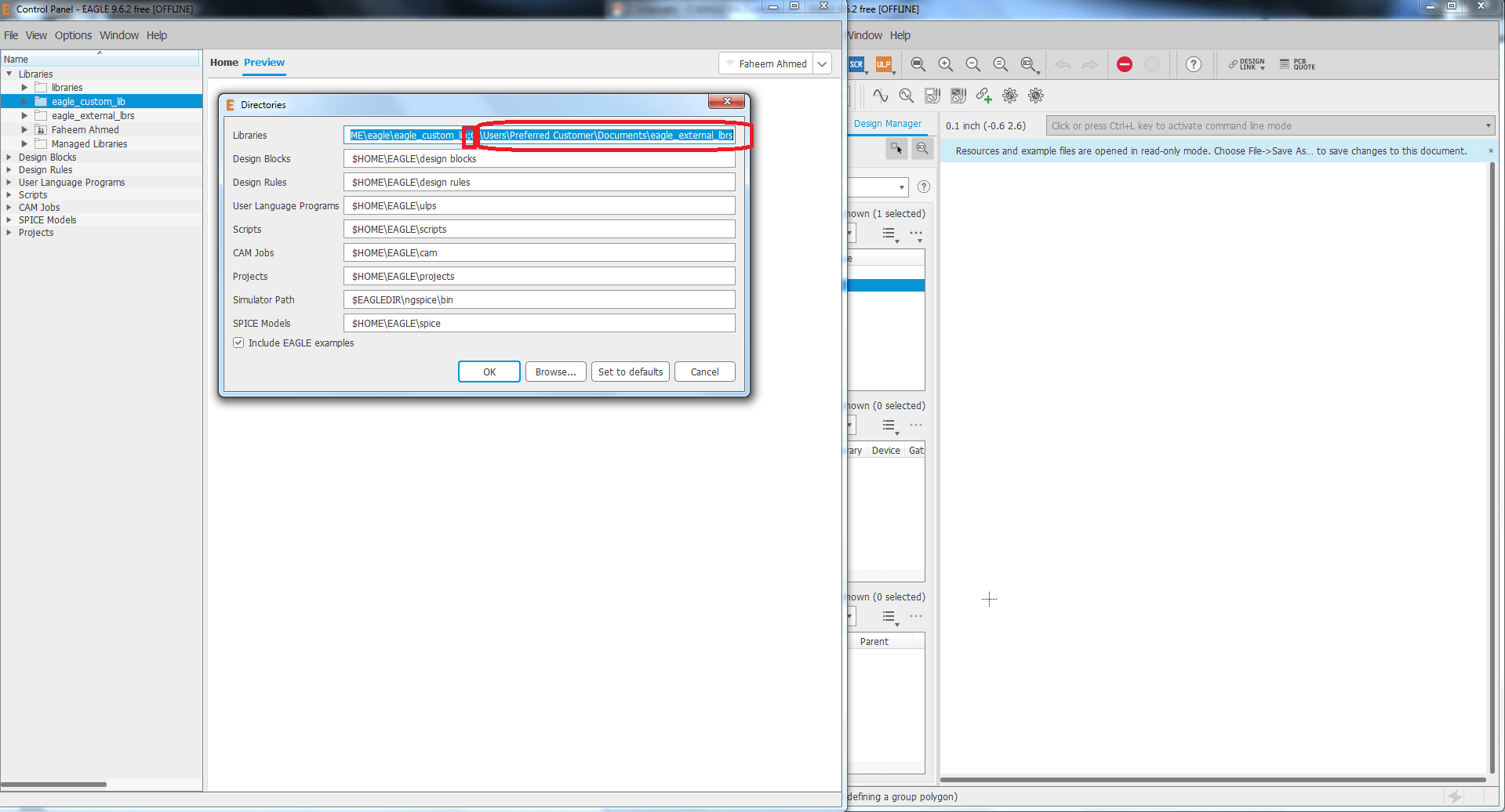
We copied the location of that folder after downloading Fablab, then opened Eagle Libraries, pasted the copied link, and pressed OK.
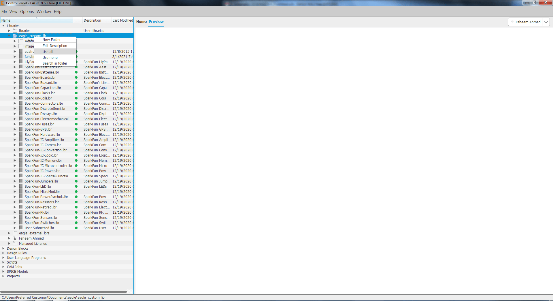
Now you can see the fablab, Right click on the folder and select use all.
List of Components
- 1x ATtiny44
- 1x 10kΩ resistors
- 1x 1uF Capacitor
- 1x FTDI Header
- 1x 6 pin AVRISP Header
- 1x 20Mhz Resonator
- 1x white LED
- 2x 0Ω resistors
- 1x 499Ω resistors
- 1xPush button
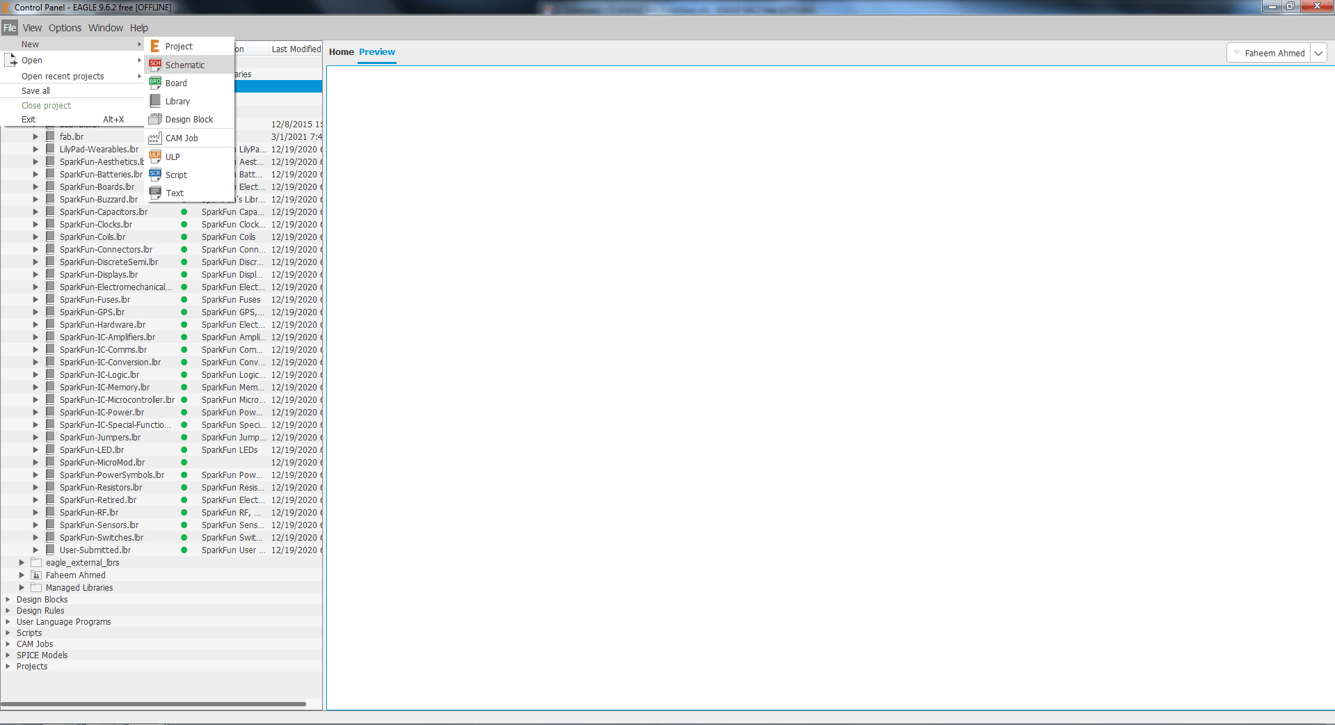
Go to file, new, Project.
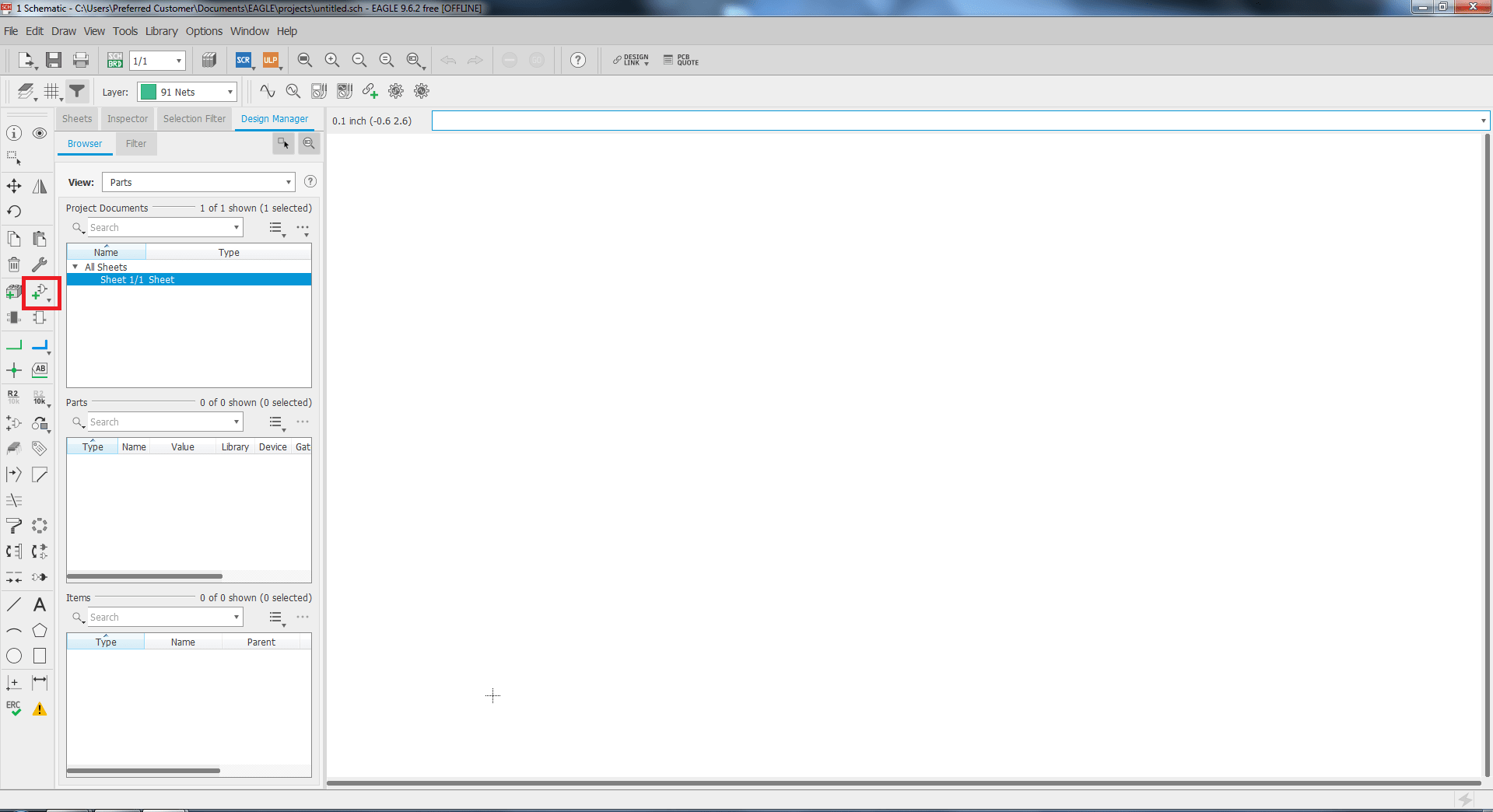
This window appear.
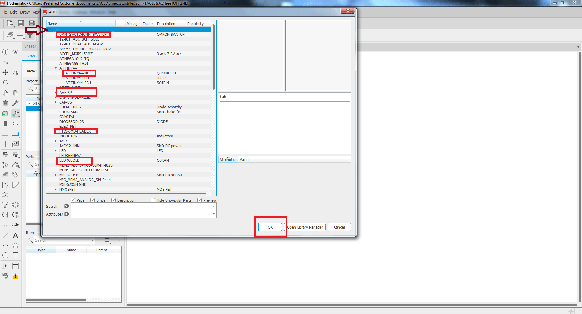
Click on add a part and select fab library select required component and place it.
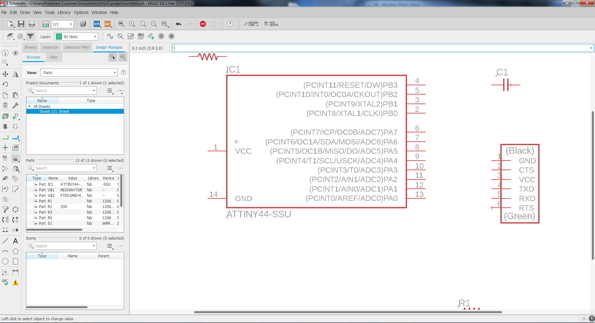
Some Required components are placed.
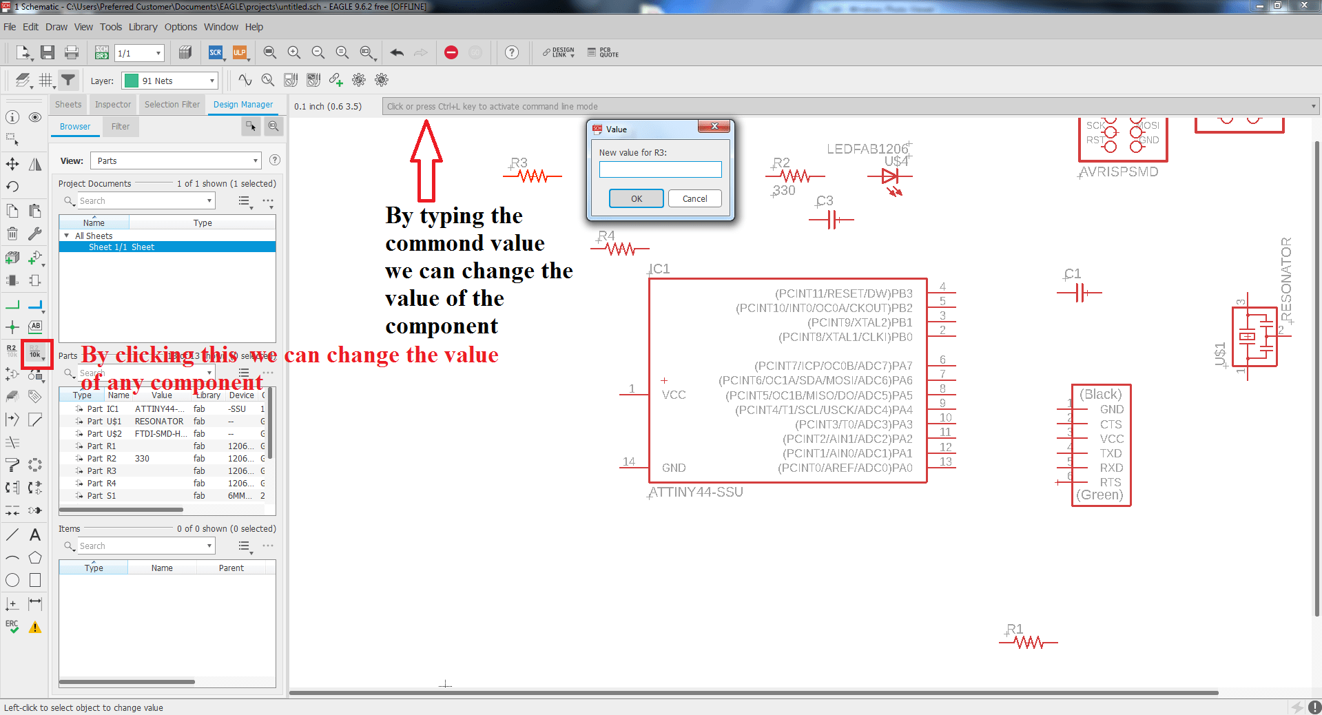
Right Click on the resister for required value.
Now its time to connect each component for this i clicked on net.
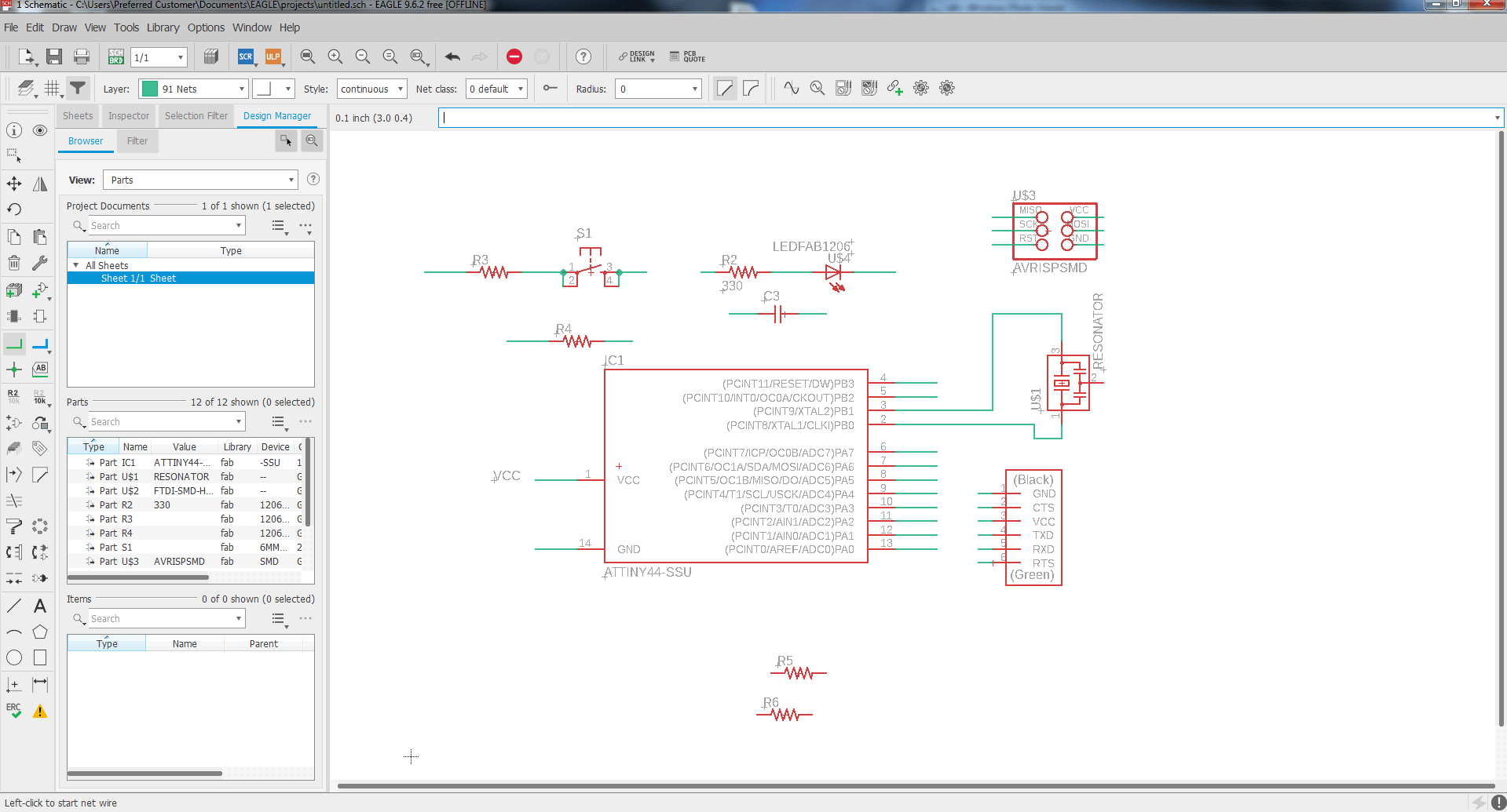
Drawn the net for connectivity of components.
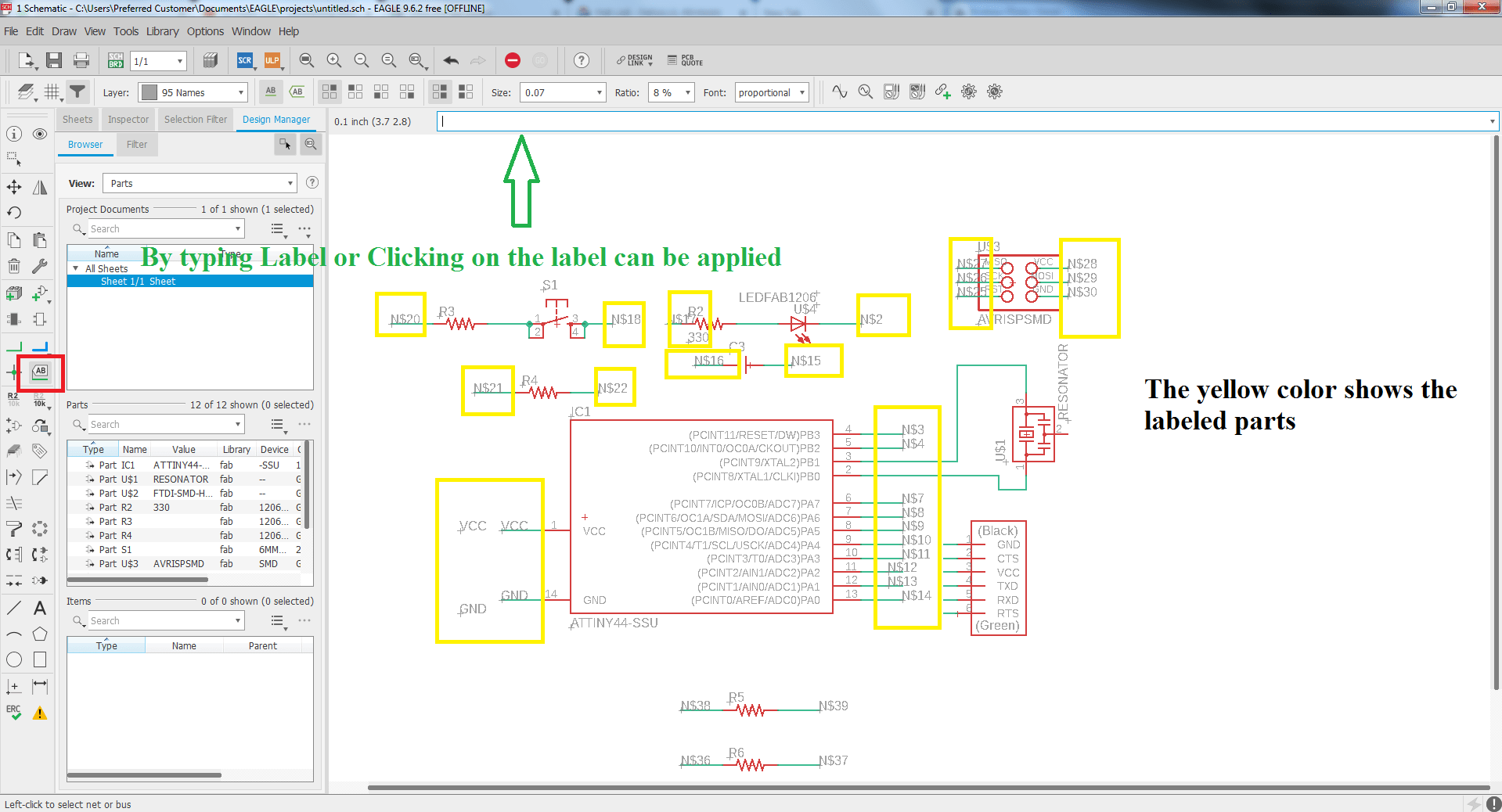
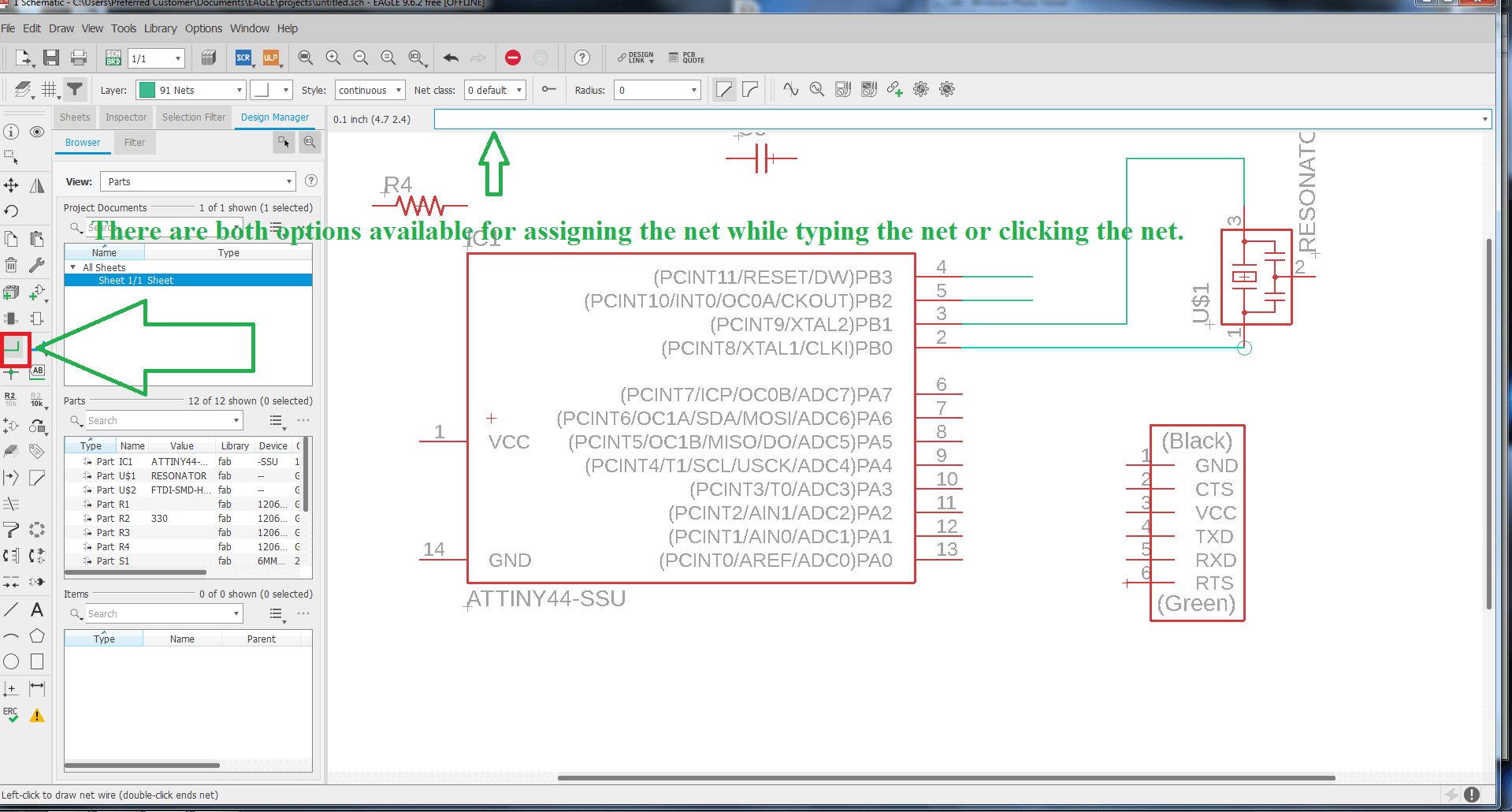
Now clicked on label and give label to each node.
Renaming of the label and then press ok.
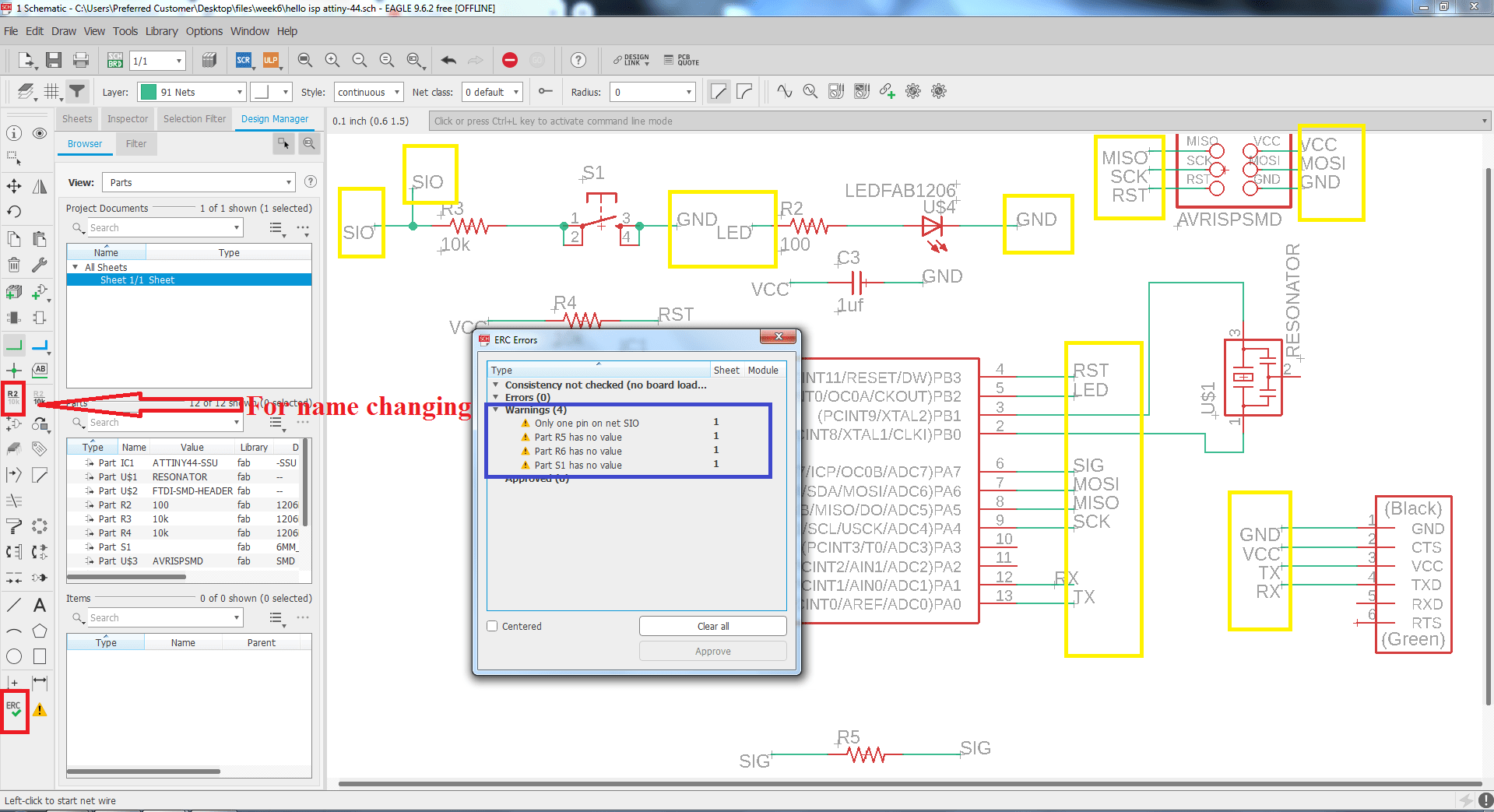
Now click on the ERC, the new window appear where you can see the ERC error.
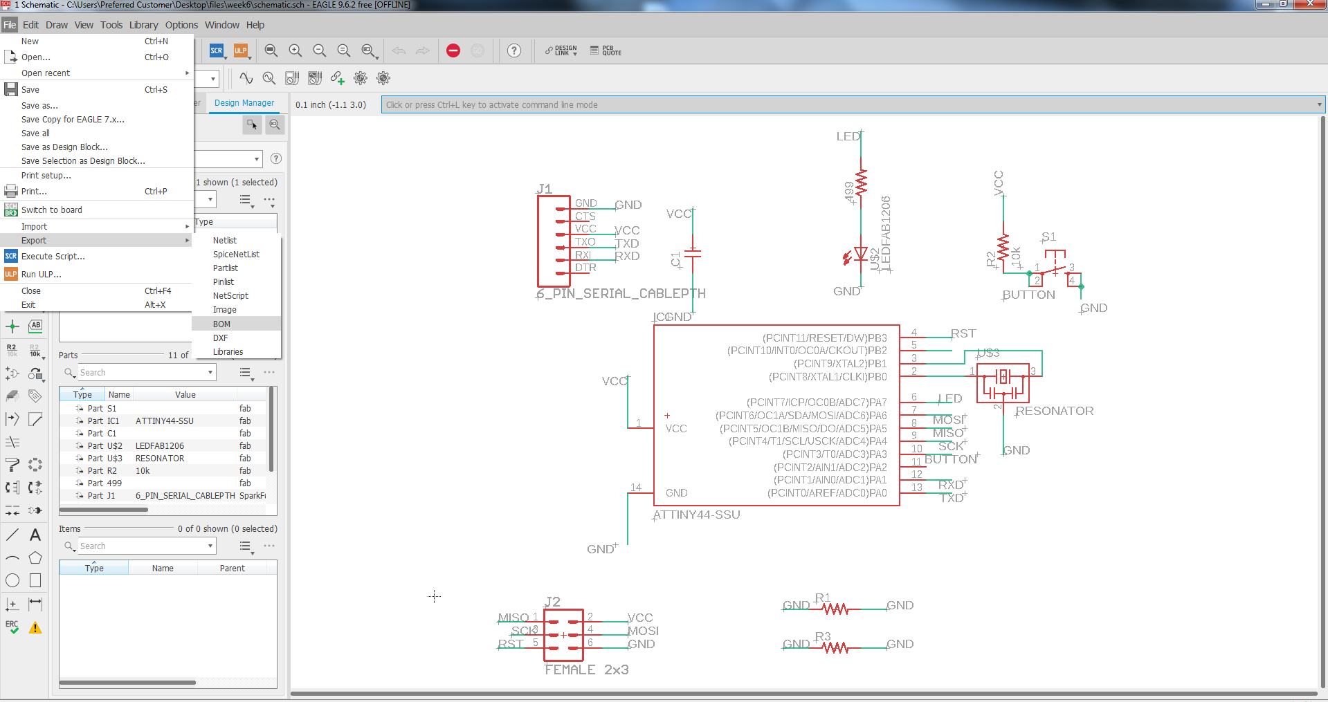
To generate the bill of material we will go to the file then export and BOM as shown in the image.
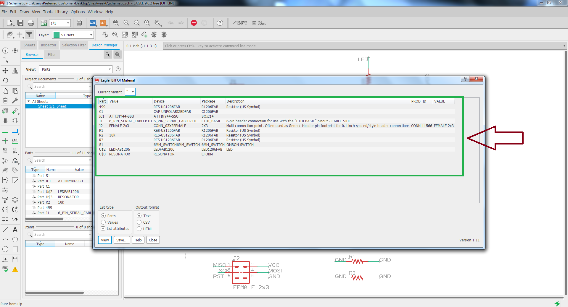
Here are the all components which is i am going to use.
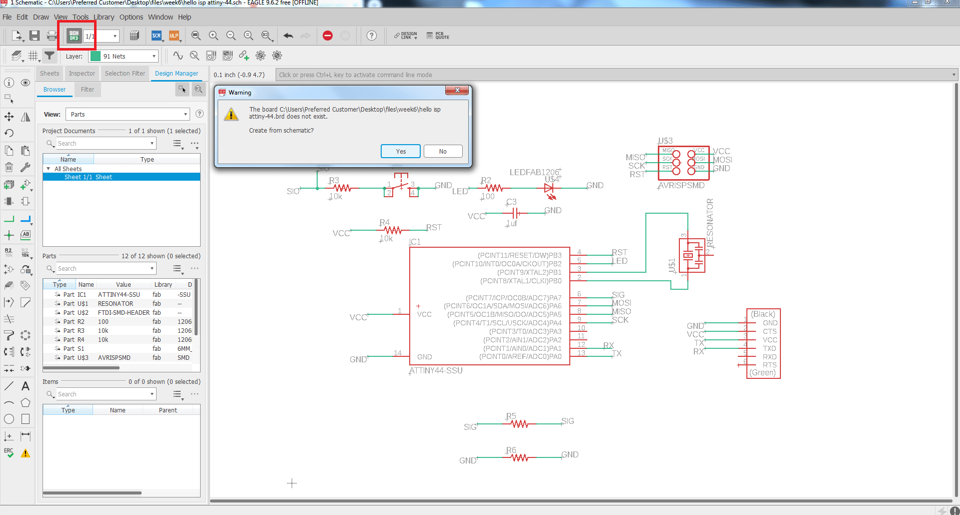
By clicking the schematic board this warning will be appear and then press yes.
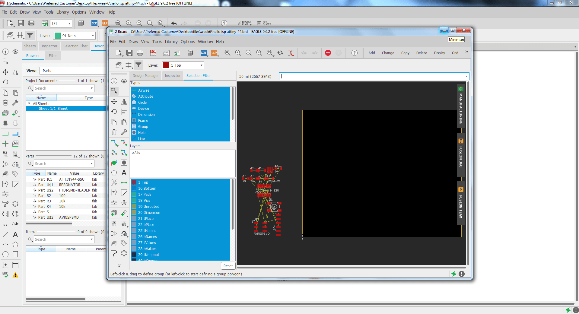
This is the bord window there you have to place the components and make routing.
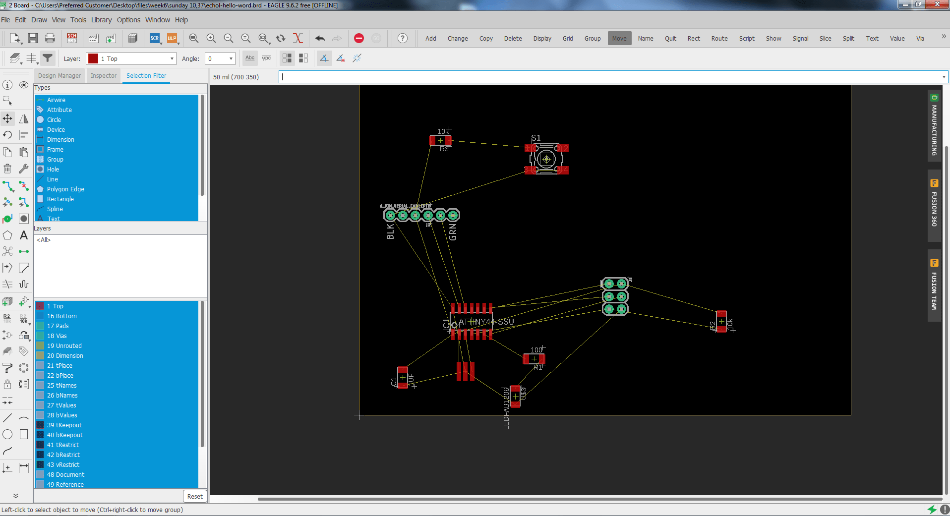
Place component for routting.
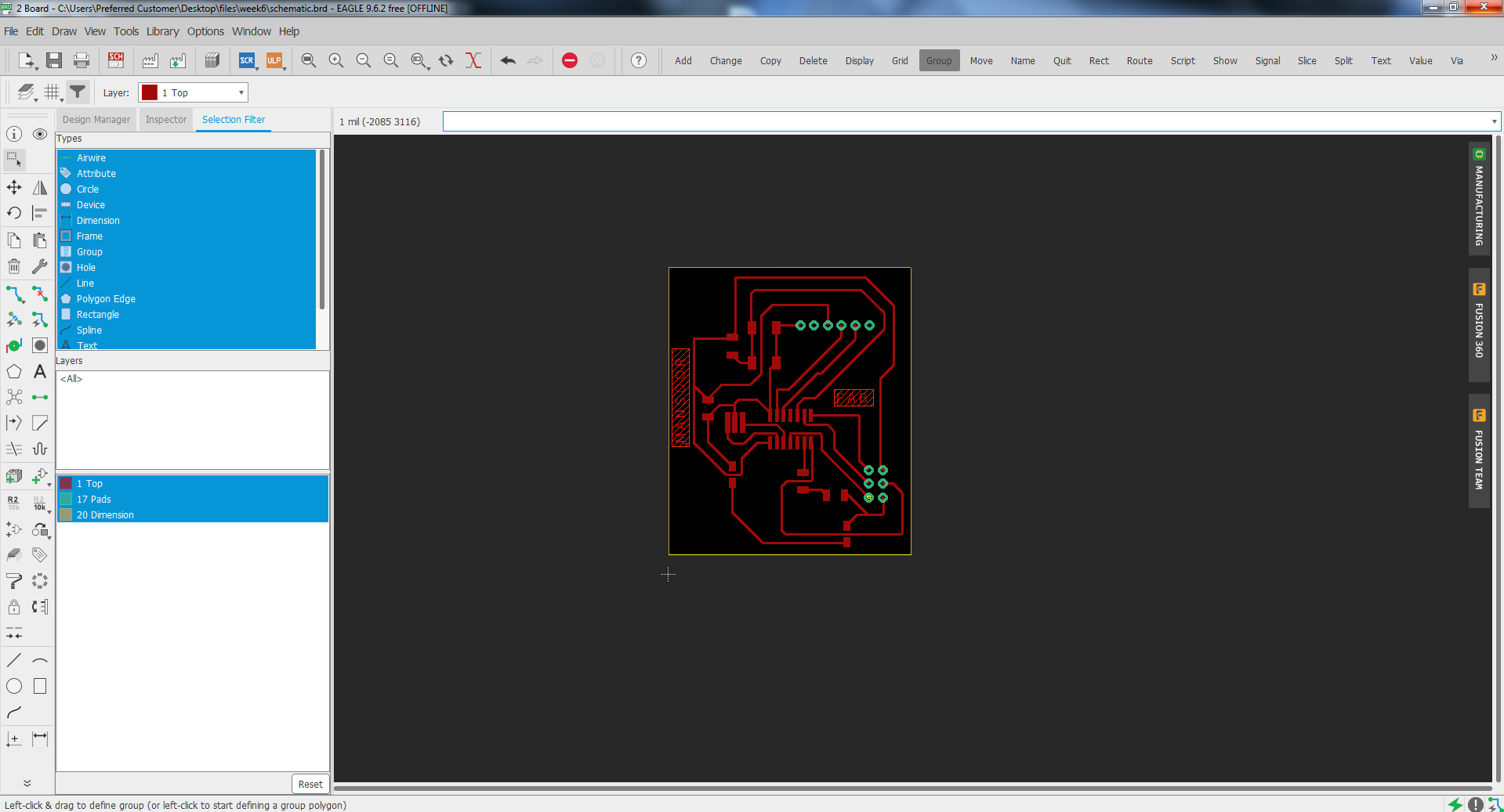
Routing complete,hide unwanted layers, go to file export as png, click on monochrome, DPI seted as 2000 and saved.
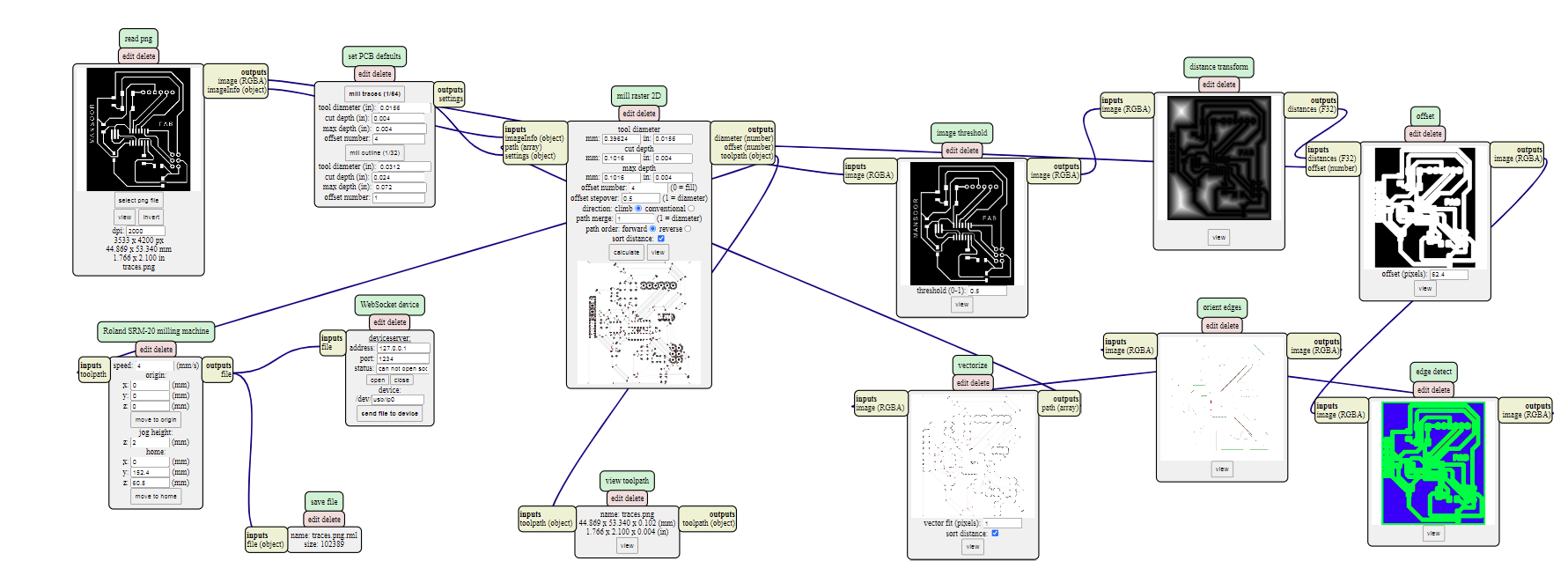
Generating RML for machine roland SRM-20 for traces select bit 1/64, for the interier used 1/32 bit and saved fils.
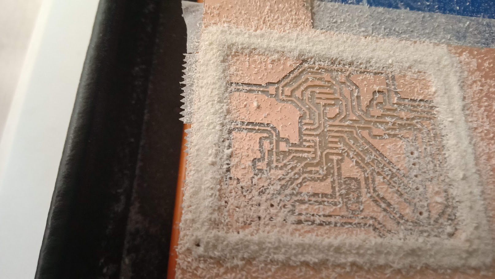
After generating the RML file we gave this to SRM-20 by using software Vpanal
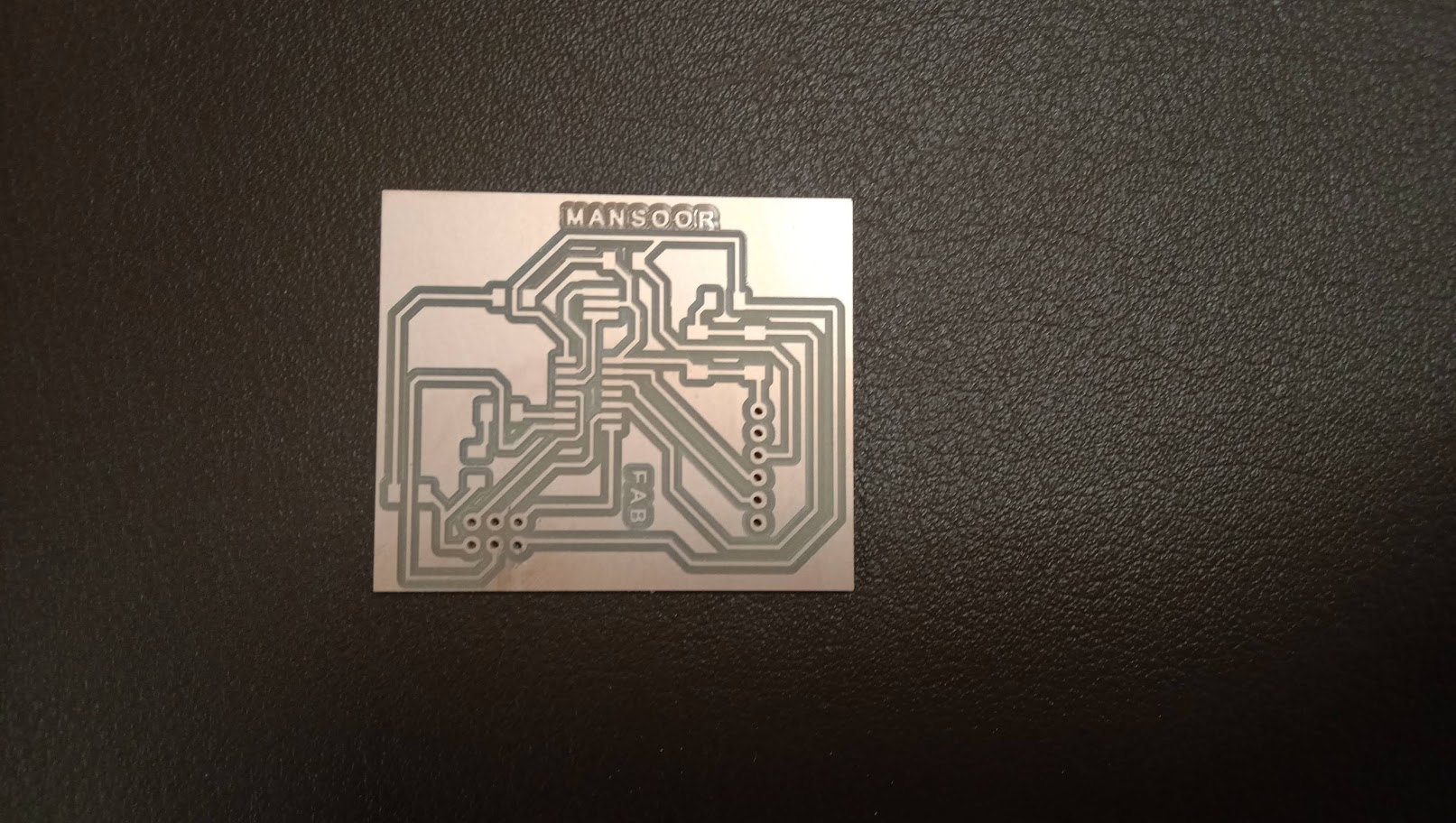
This is the requied milled PCB
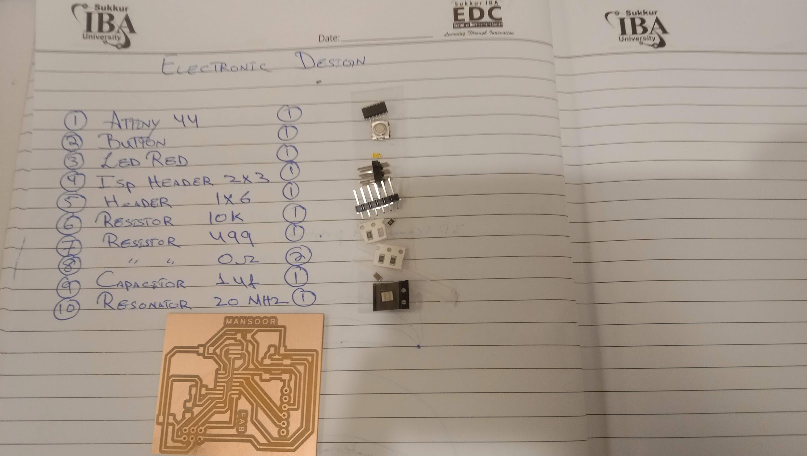
This is the list of components which i have to solder.
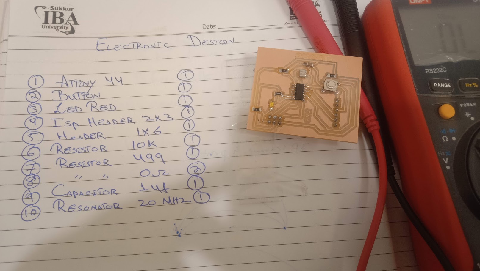
After solidering i checked the connectivity of my circuit.
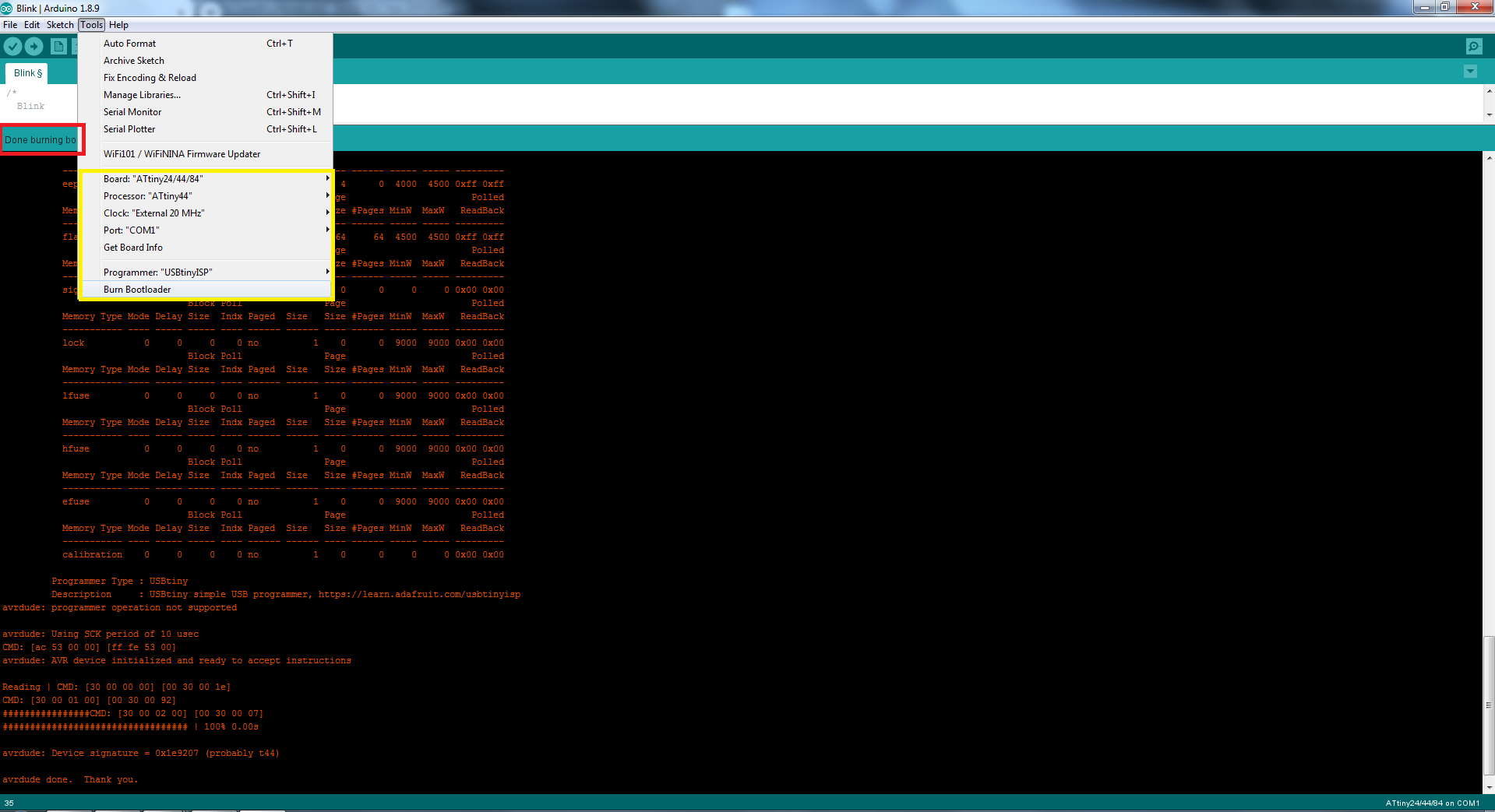
For boot loading we open to ardiuno software then the Board Manager and select the Board attiny44/85/25 after set the Prcossor Attiny-44 and in last Select the 20MHz clock processor.
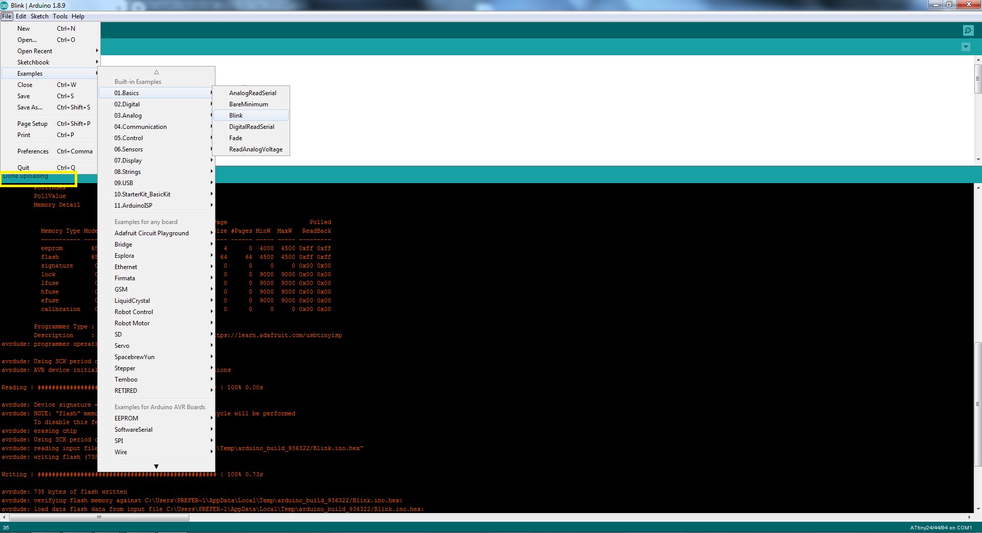
click on the file, go to examples,basics, blink andAfter solidering i checked the connectivity of my circuit.
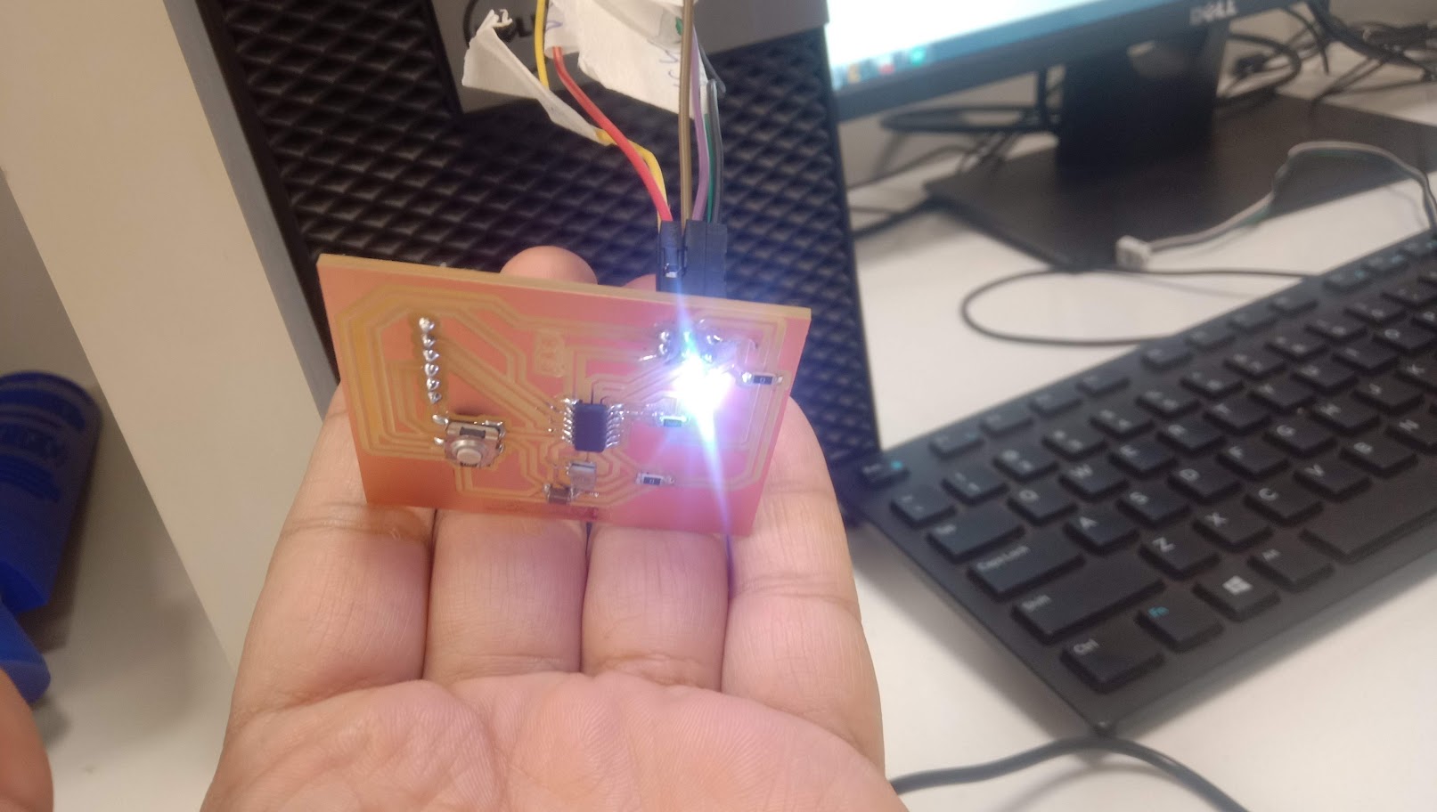
Here you can see the LED is bling.
Group Assignment
Use the test equipment in your lab to observe the operation of a microcontroller circuit board.
We used range automatic digital meter to check the polarities of the LED, resistance and capacitance and the continuity of the circuit board.
Resistor
Resistors are very essential part of Electronics circuit. The value of resistor is very important. If we place resistor of wrong value at any place in circuit, circuit may not work or in some cases it can affect other components as well. Resistors are non-polarized. Rotate the dial of multimeter to resistance and put both probes of multimeter across the resistor. Value will be displayed on screen of multimeter.
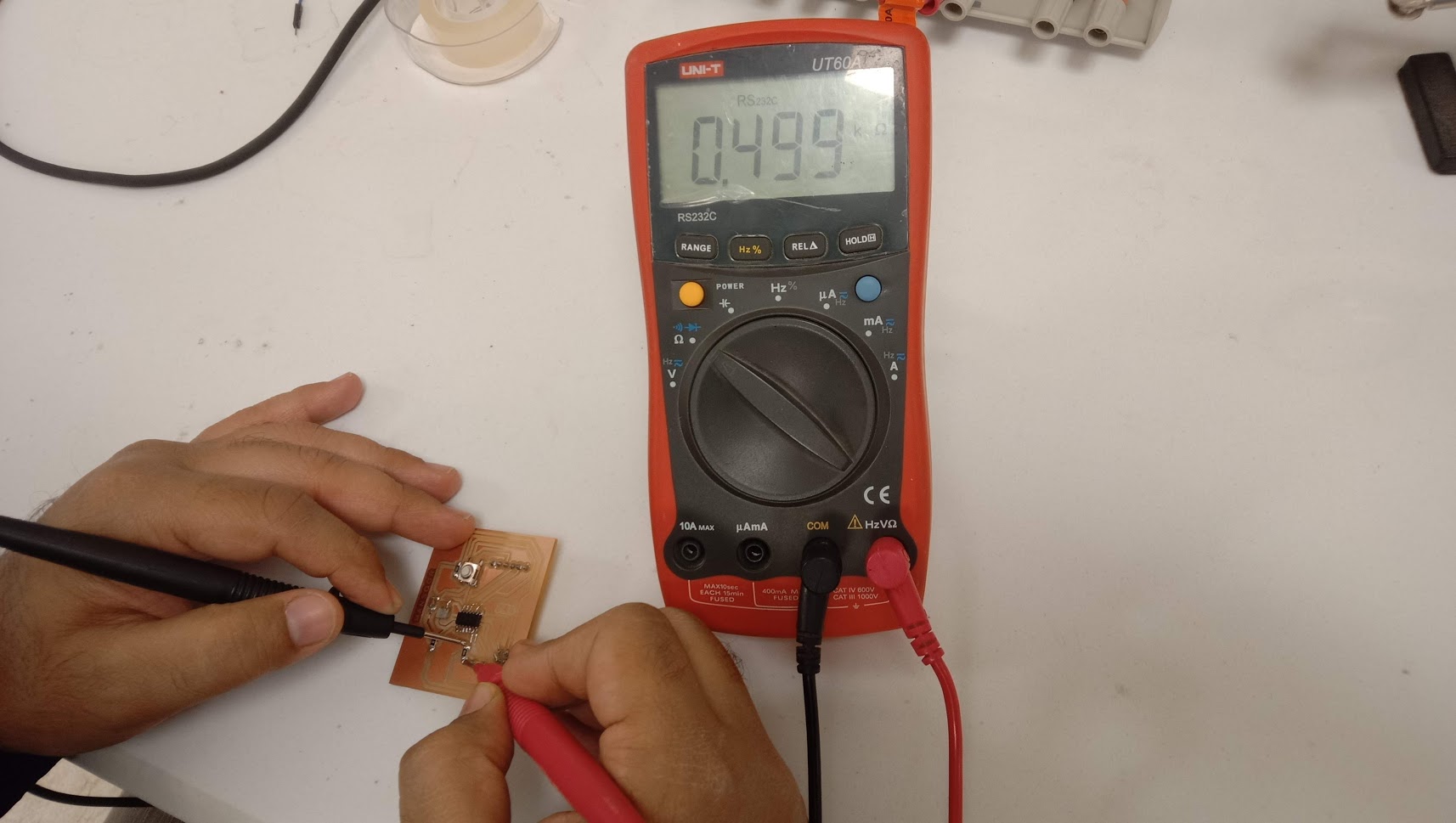
This is the resister value.
Capacitor
SMD capacitors are just one form of component that uses surface mount technology. This form of component technology has now become commonplace for manufacturing electronic equipment as it enables much faster and more reliable construction of electronic printed circuit boards.
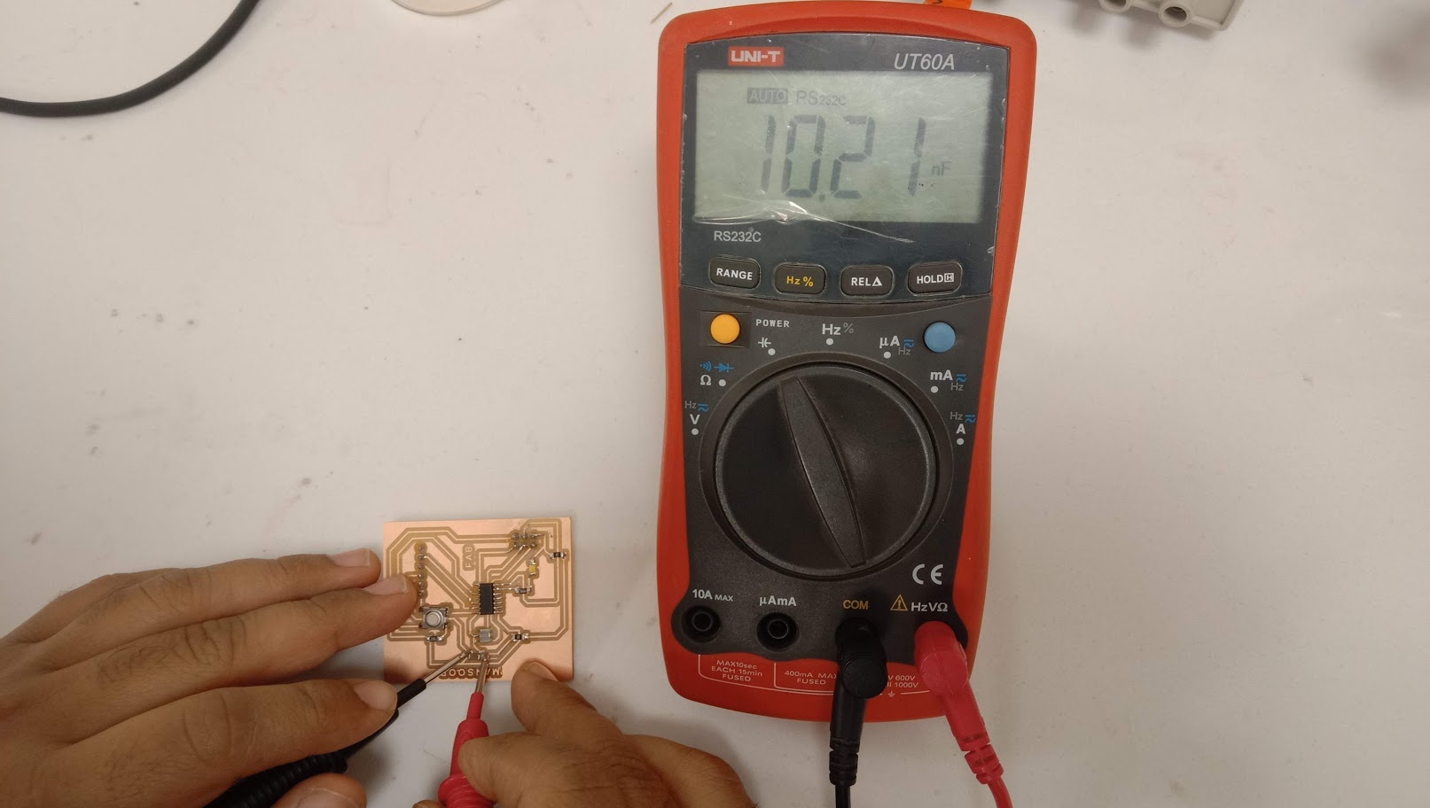
Capacitance can be seen on the meter.
continuity
Continuity testing is the act of testing the resistance between two points.If there is more than a few ohms of resistance, than the circuit is open, and no tone is emitted.Second until they fill up with energy, and then act like an open connection.
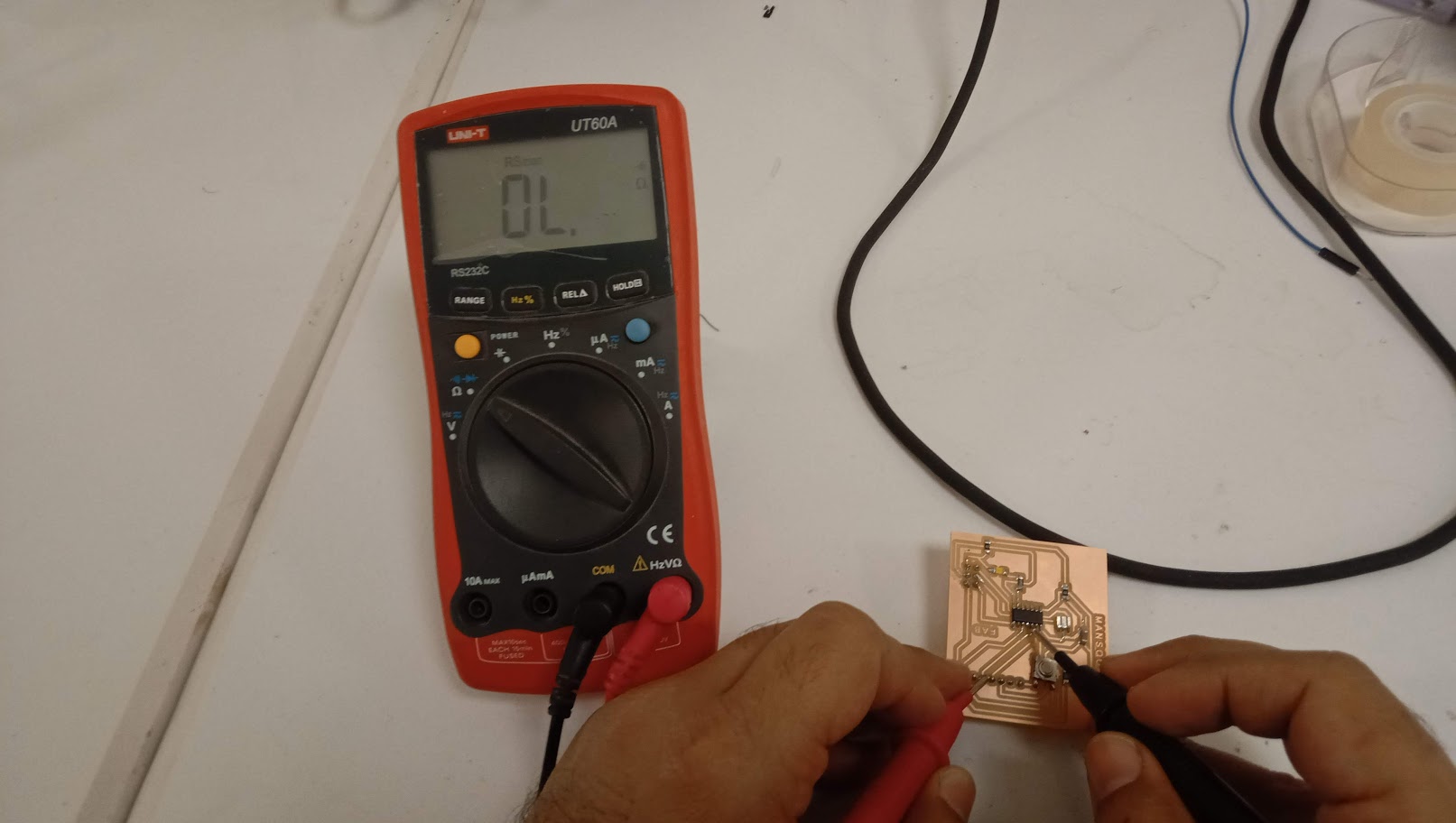
Checking the connectivity.
LED
Second test is to make sure that LED is correctly soldered and polarities of LEDs are correct. In order to test the LED, rotate the dial on multimeter to LED and put cathode to ground and anode to the supply side of LED. If led glow then LED is perfect in position. If LED do not glow, check the soldering and/or the polarity may be reversed..
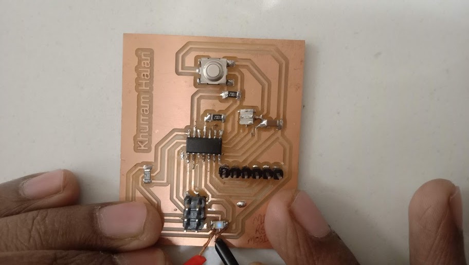
Now we are checking the polarty of LED.
"Click here"to download all files of this week