
|

| Sukkur IBA University Merit, Quality, Excellence |
Week - 5
3-D Scanning and Printing
Assignment
Group Assignment: Test the design rules for your printer. Individual Assignment is Design and 3D print an object (small, few cm) that is Additive. And also scan 3D an object.
specifications of Ultimaker 2+:
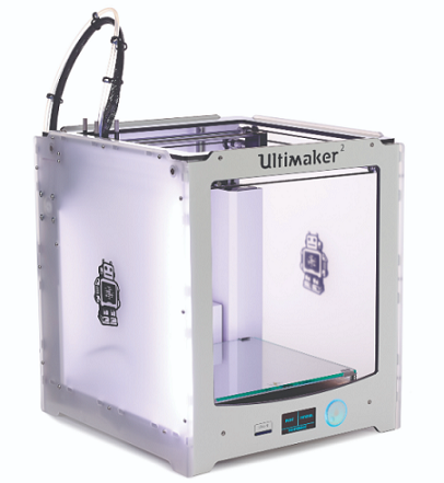
This is the 3d Printer of ultimaker 2+ specifications can be ssen below.
Build Volume: 223mm A--223mm A--205mm Layer resolution: up to 20 microns Print Speed: 30mm - 300mm/s Travel speed:30mm - 300mm/s Filament diameter: 2.85mm recommended Nozzle diameter: 0.4mm swappable Operating nozzle temperature: 180A C-260A C Operating heated bed temperature: 50A Centigrate 100A Centigrate Frame Dimensions: 342x493x588 mm Printer technology: Fused Filament Fabrication (FFF) Software: Cura
Extruder
Same as other typical 3D printer, Ultimaker 2+ has an extruder which consist of a filament driver and a thermal hot end. The filament driver pull in the filament (eg. 2.85mm diameter) which is then fed to the thermal hot end. The filament which is in-turn melted to a temperature of between 170 degree celcius to 220 degree celcius, depend on the filament material used. The semi-liquid plastic is then forced out of the print nozzel which is around 0.4mm in diameter and onto the printbed. Printing line-by-line and layer-by-layer forming the shape of the 3D model that you want to print.
Slicing software
Ultimaker's slicing app "Cura" prepares the 3D sample file for printing with the Ultimaker 2+ 3D printer. Thet STL (or OBJ) file is converted to gcode using slicing tools. The gcode tells the 3D printer where to move the print head, how quickly it should move, and what direction it should take.
Input media
The Ultimaker 2+ has an SD Card slot that supports SD Cards with storage capacities of up to 32GB for direct printing without the need for a computer. It's worth noting that if you have a 64GB SD Card, the computer won't be able to read it. Copy the gcode to the SD Card so that it can be loaded into the 3D Printer and printed.
Maintainance of Ultimaker 2 +
In our fab lab, we have Ultimaker 2+ and Ultimaker Extended 2+.In Ultimaker 2 extended filament is broken due to humidity and the other printer nozzle is jammed so, we need to open the nozzle and clean it and remove the carbon inside the nozzle.
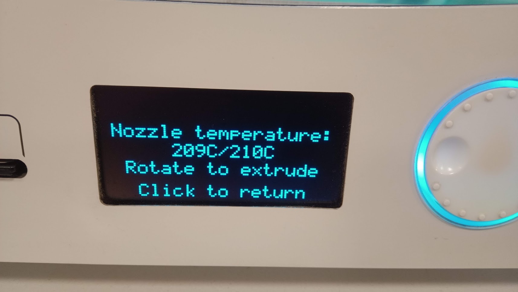
The filament of material is broken that's why we need to give temperature to the filament and the melting temperature of PLA material is between 180 to 210 and rotate to extrude.
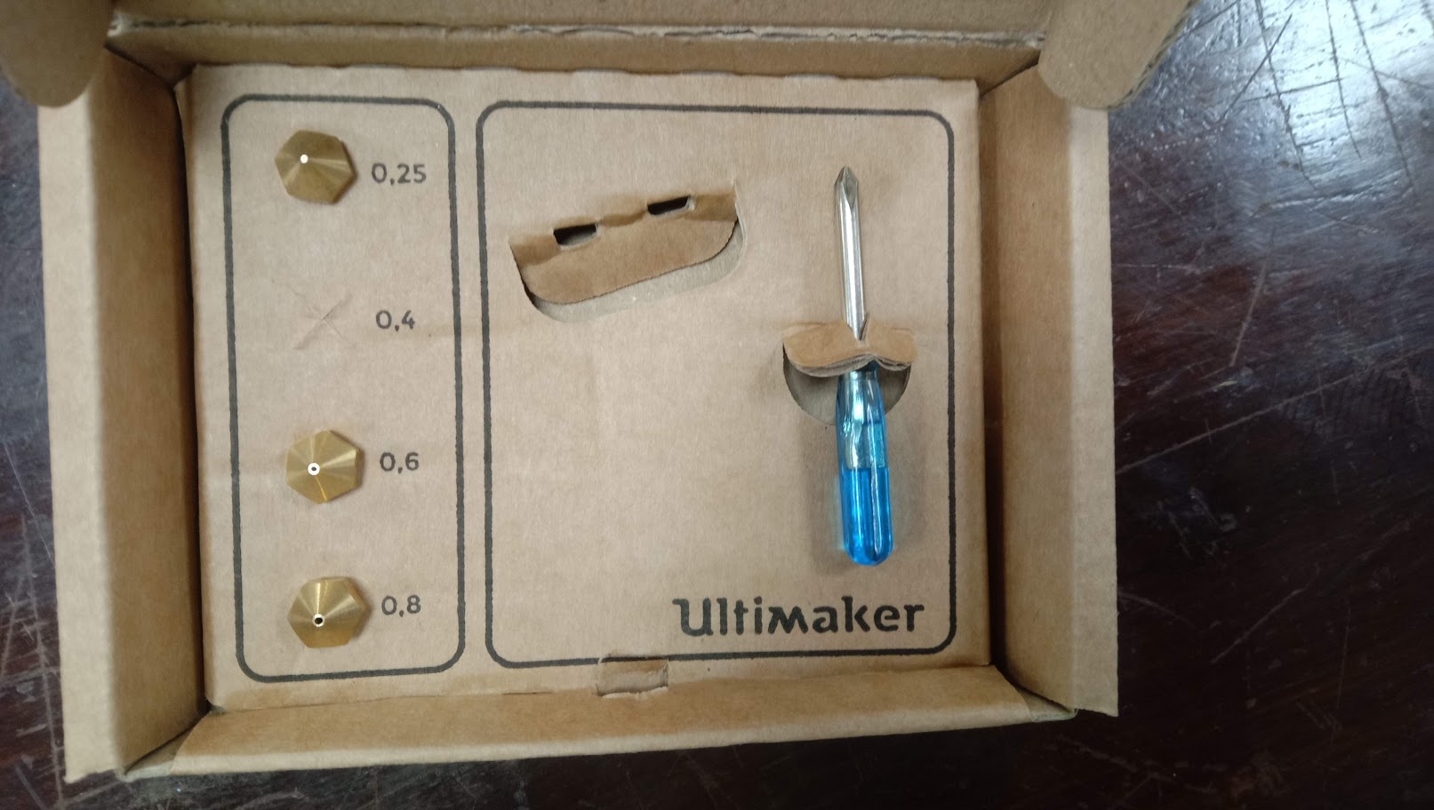
This is the toolkit of Ultimaker. The 0.4 mm nozzle is installed in the printer.
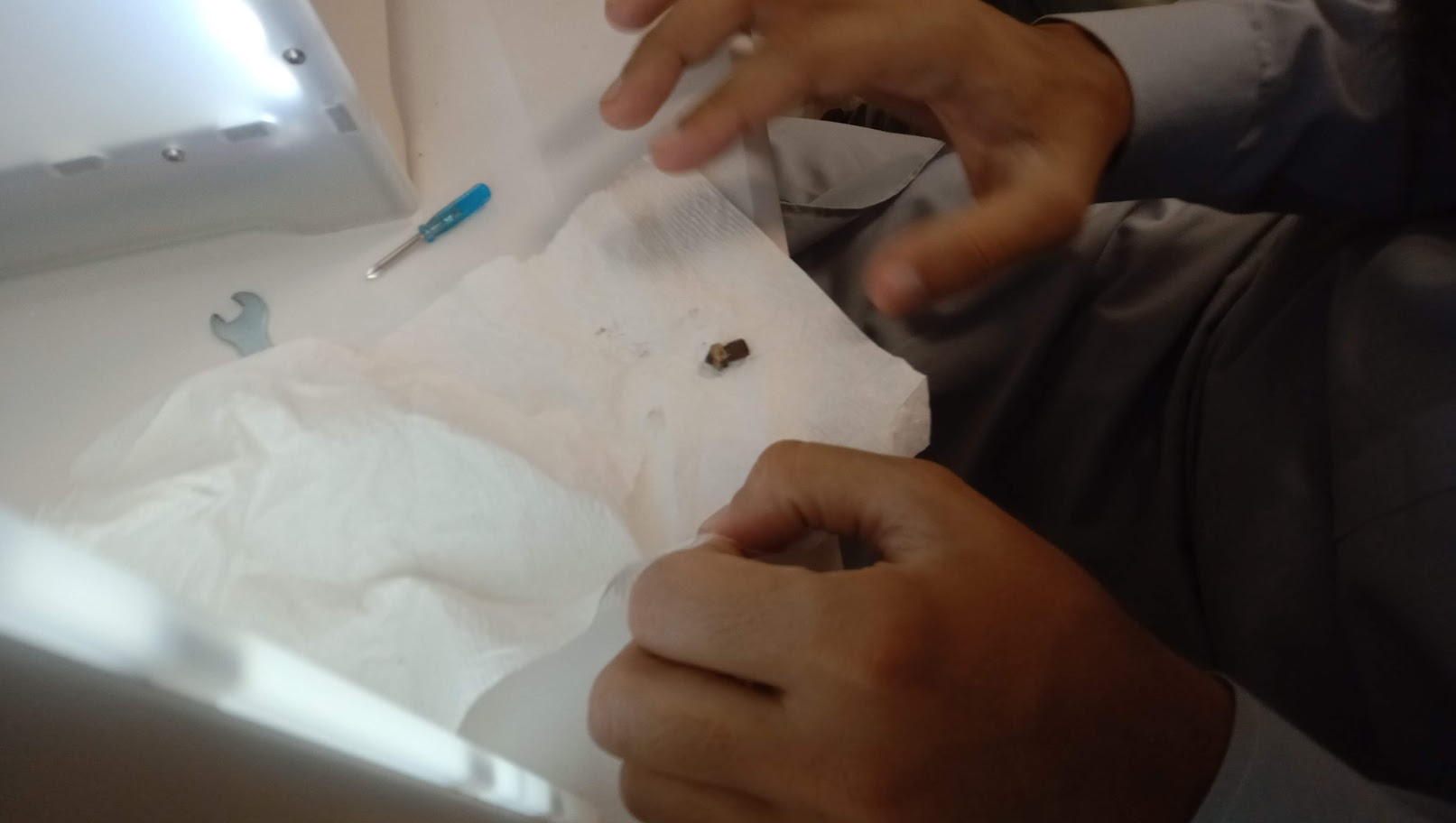
We remove the nozzle from the printer and take out solid material which was inside the nozzle.
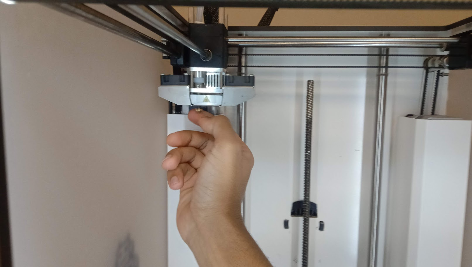
Now fixing the neat and cleaned nozzle.
Group Assignment
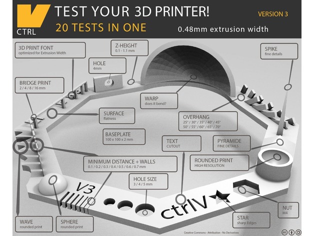
Testing the design rules for the Printing the 3D Objects we are using .STL file We have downloaded a standard test 3D file from the thingivers.com this file can be downloaded from here: here
We import this file in to Cura software and set the Parameters with respect to ultimaker 2+ printer.
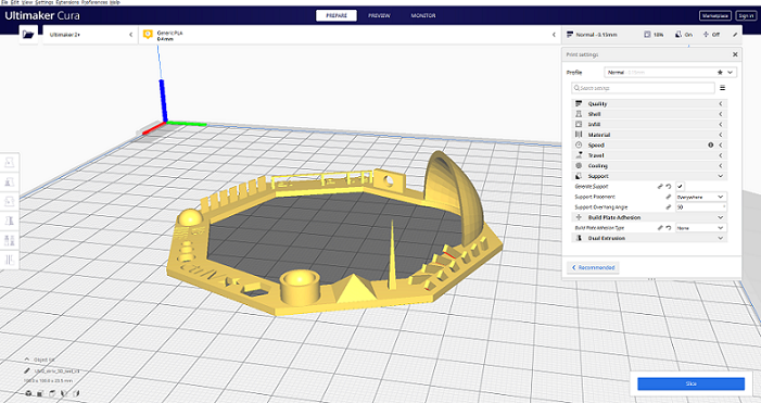
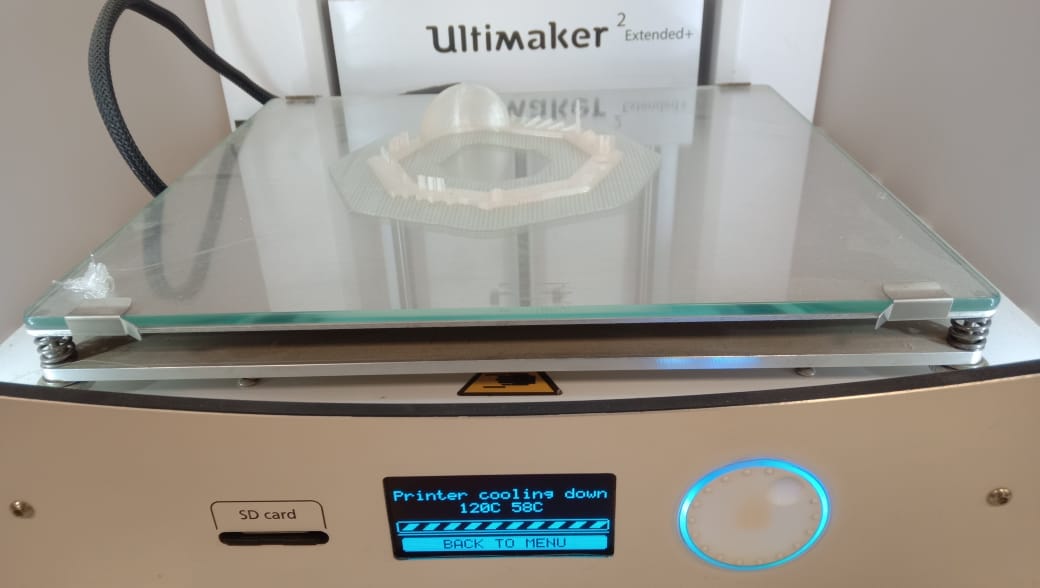
Insert the cura file which format is .gcode in 3D printer ultimate 2+.

Final result have some misprinting. So, we make another print.
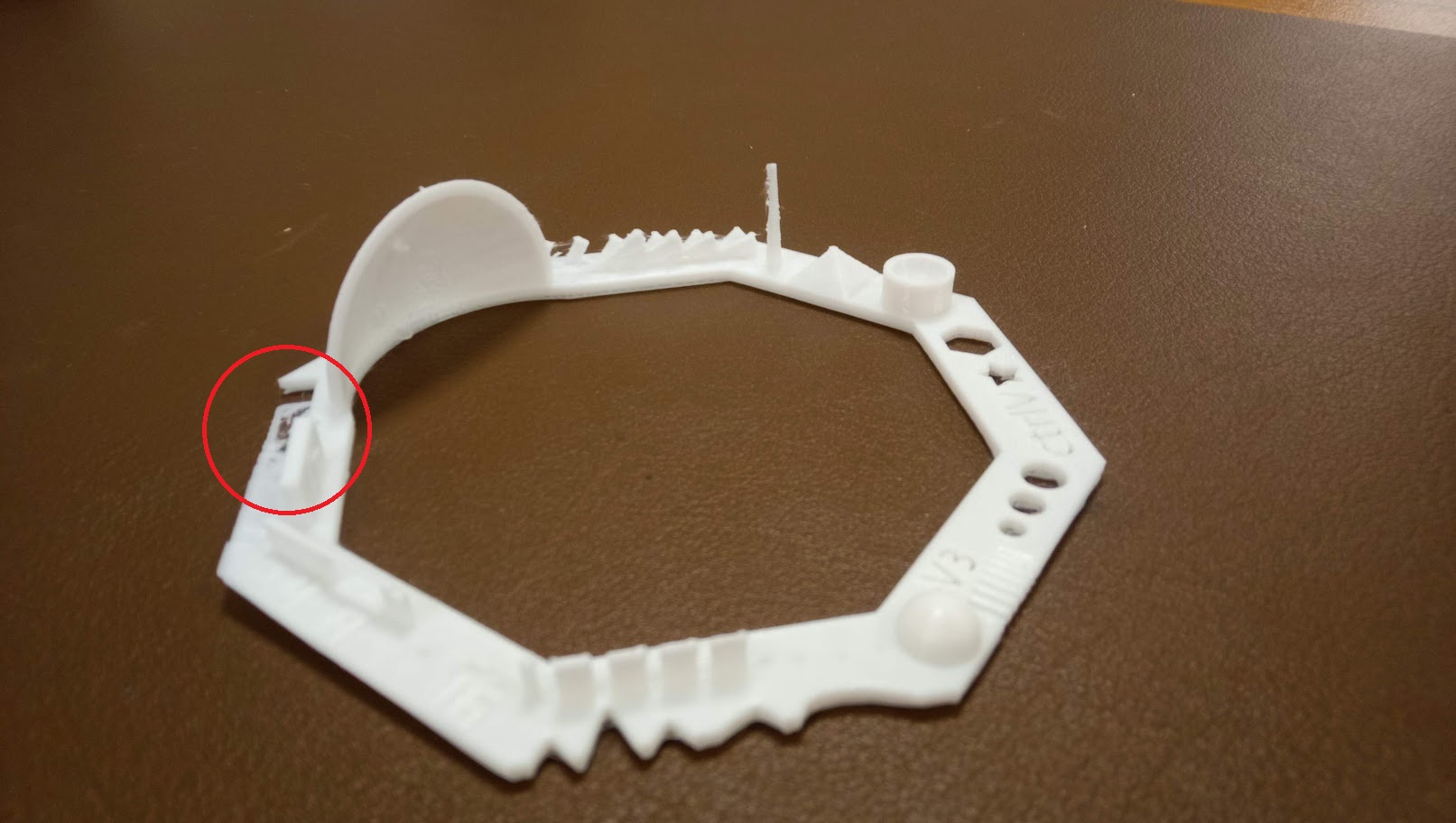
we printed another test card with some print setting there was no support, raft included, resolution 0.1mm or higher and infill was 30%.
MEASURE THE HOLE IN WALL DIAMETER
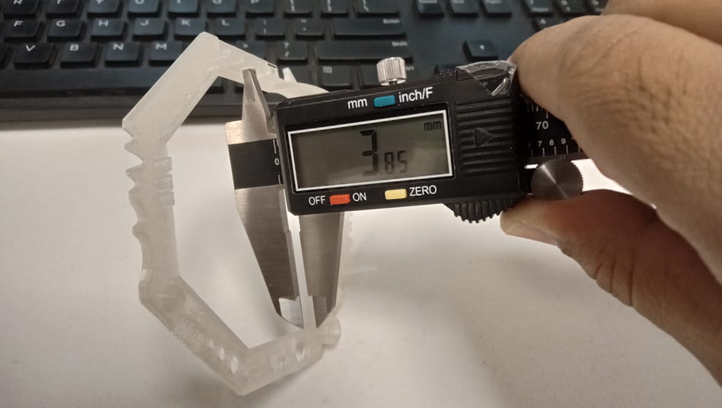
According to test specification the Hole in Wall diameter is 4mm but in actual it is 3.85mm.
MEASURE NUT SLOT
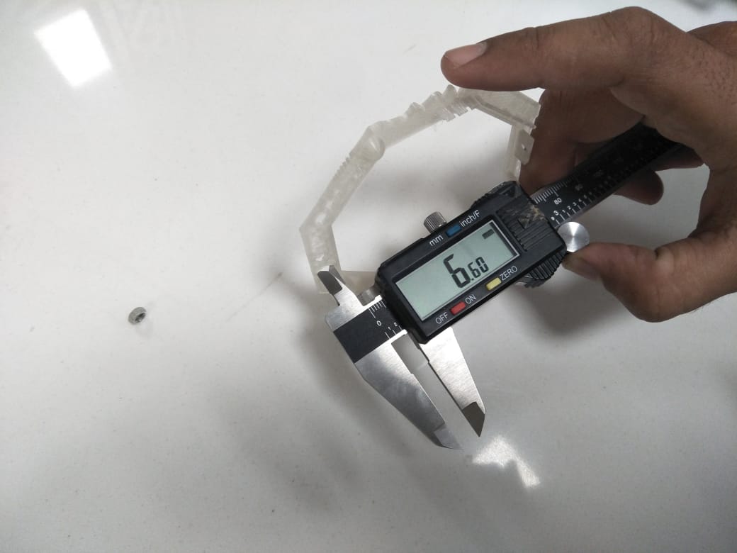
Checking the nut size in 3D test card we measure nut slot size with the help of vernier caliper.
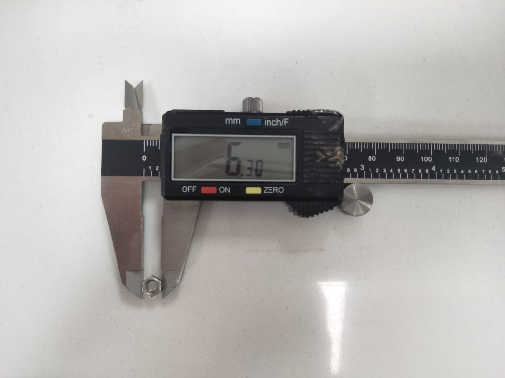
measuring the nut size in mm for checking the 3D test card nut slot.
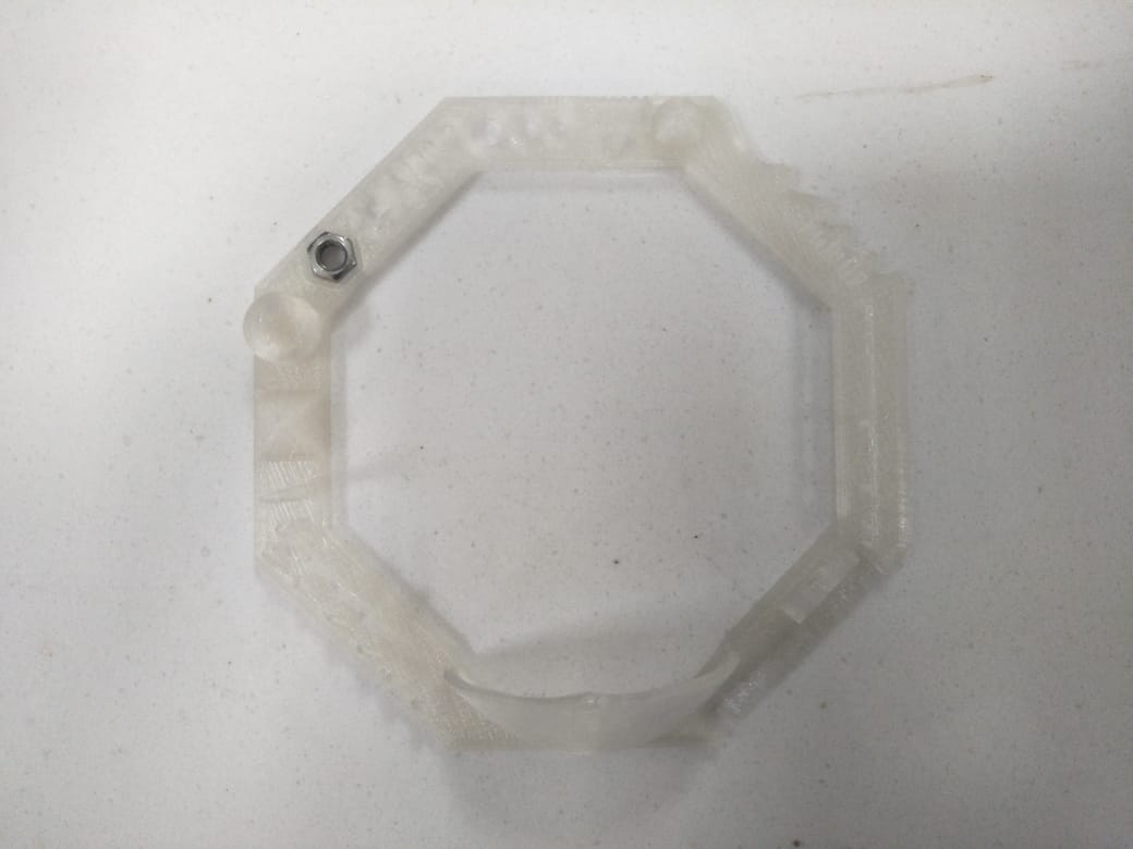
We can observe that there is the approximetly 0.30mm difference between nut and slot.
MEASURE THE PYRAMID
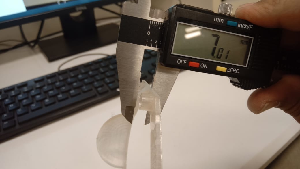
In pyramid there is only 0.01mm difference actually it is 7mm but when we measured it was 7.01mm.
Learning from this week Following settings are available in Cura.
Support: Anything with a slope of less than 70 degrees does not need support in order to print.
layer height: One of the most frequently adjusted settings is the layer height. In millimeters, it is the thickness of one written layer. With a thinner layer height, you can boost the print quality, resulting in a smoother surface and more detail noticeable in the model's Z-direction (height).
Wall thickness and wall line count: This parameter influences the model's wall thickness. The wall thickness is rounded to a multiple of the line width in Ultimaker Cura. A wall thickness of two to three times the line width is sufficient in most cases.
Top/bottom thickness: The top/bottom thickness influences the thickness of the print's solidly printed top and bottom layers. A higher value guarantees that all holes on the top and bottom layers are absolutely closed.
Infill density: The amount of plastic used on the inside of the print is determined by the infill density. A higher infill density suggests that more plastic is present on the inside of your print, resulting in a more durable item. For models with a visual intent, an infill density of around 20% is used; for end-use sections, higher densities can be used.
The print speed: It defines the speed (in mm/s) at which the print head moves while printing. Based on this setting, Ultimaker Cura calculates the extrusion flow.
Build plate Adhesion type: Extrusion priming and adhesion to the build plate can be enhanced with a variety of choices. To avoid wrapping, Brim adds a single layer flat area around the base of your model. Below the model, Raft adds a dense grid with a roof. Skirt is a line that runs around the model but is not bound to it.
Individual Assignment
Design an object which must be additive design and print it. Scan a 3d object.
Design and print a 3D model
In this week's assignment, I am planning to make a non-subtractive Design
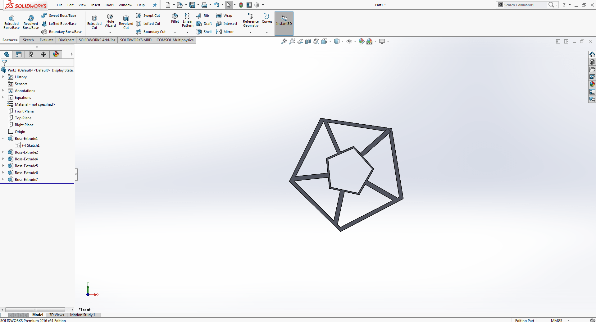
Here is the desired outcome that I want to achieve.
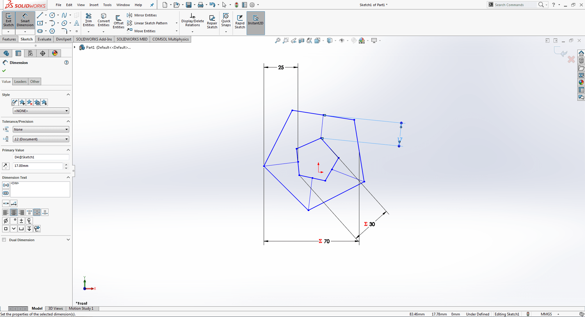
Simply by selecting on hexagonal and adding 5 points to it, it becomes a pentagonal shape, and then assigning smart dimensions from previous week-2 practise, I am able to achieve the desired result.
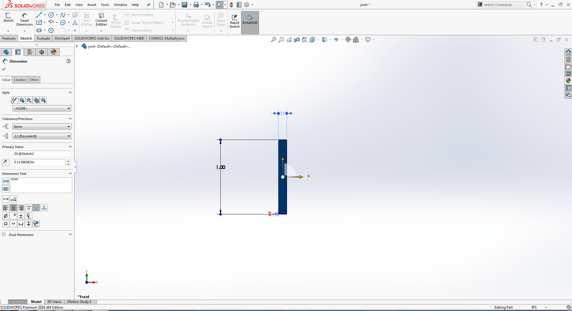
After go to the futres extruded boss/bass then i give the width 4mm and press enter.
This is the front view of pentagonal shape. Save it as a separate file.
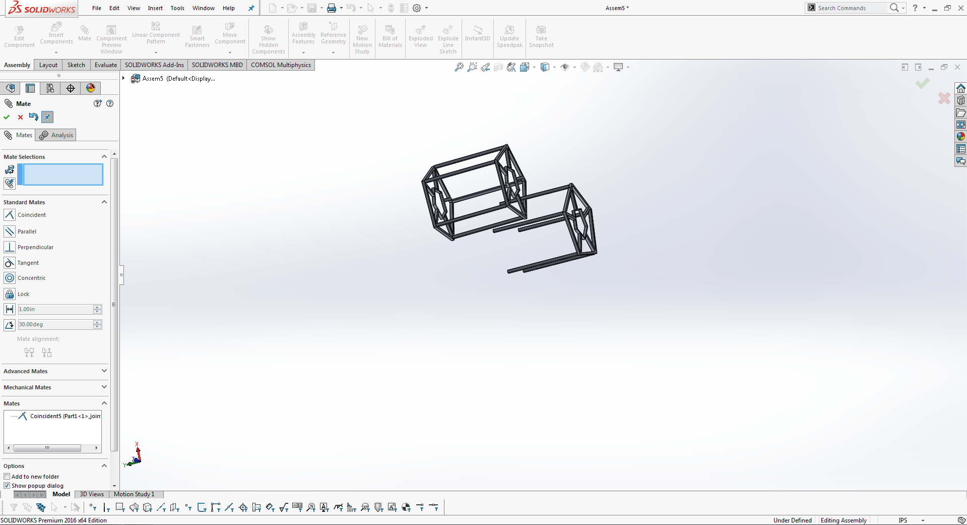
Then i maked supporting part.
This is an other part of design.
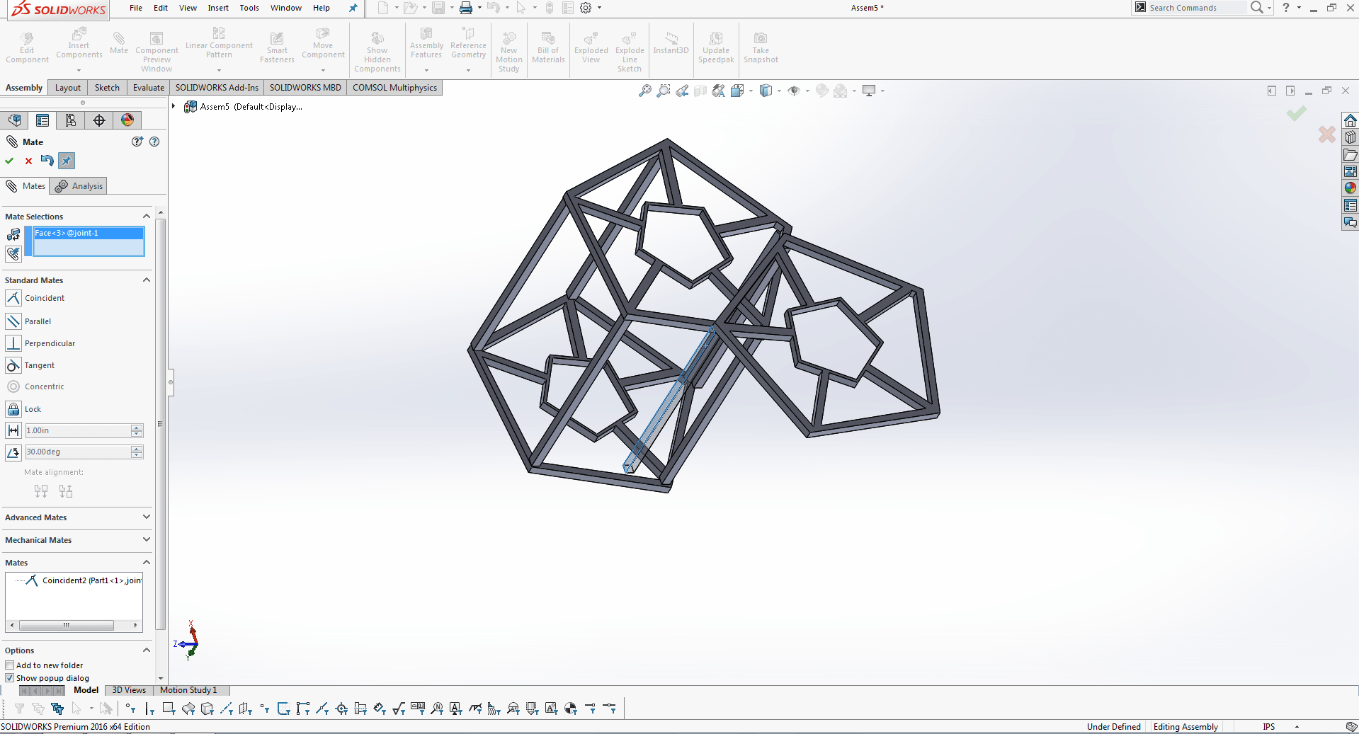
After that i brownse the all parts and mate some of them parts.
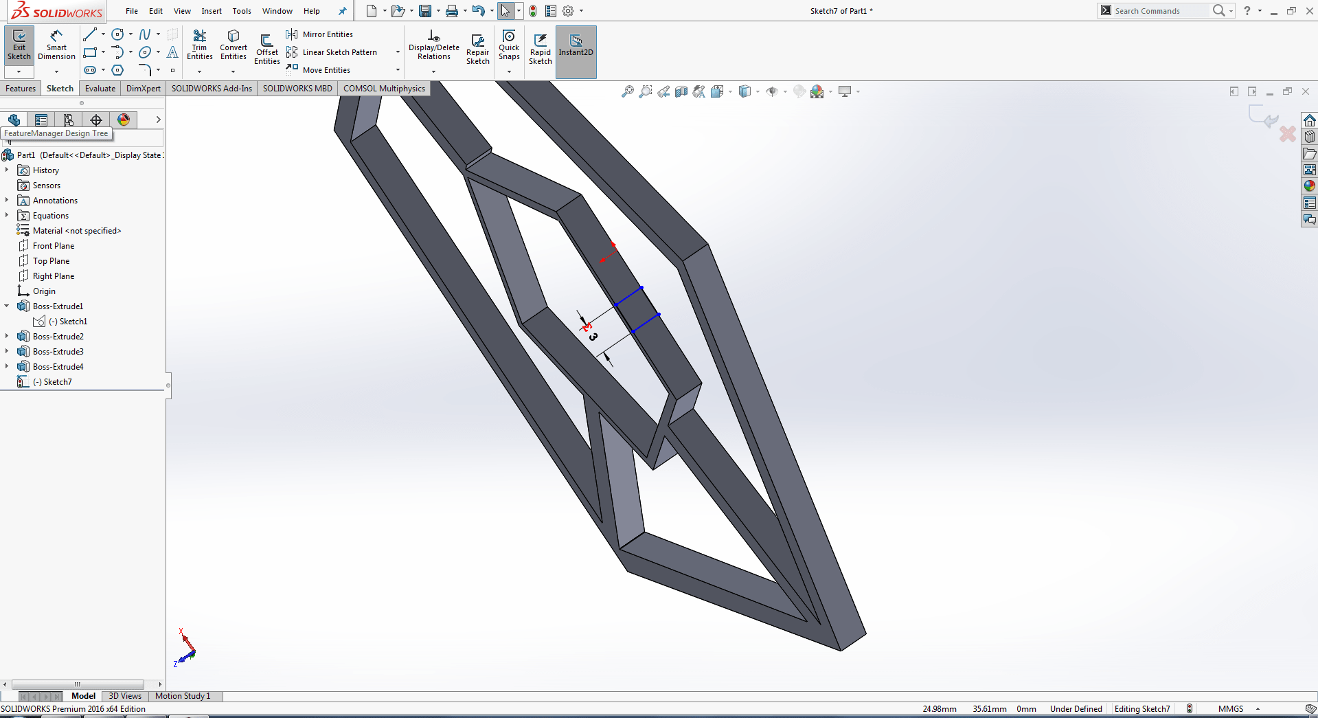
Now this is very important part which i am mating one side only it makes my design into additive.
Two pentagonal shapes are joint to make additive design as you can seen in my image.
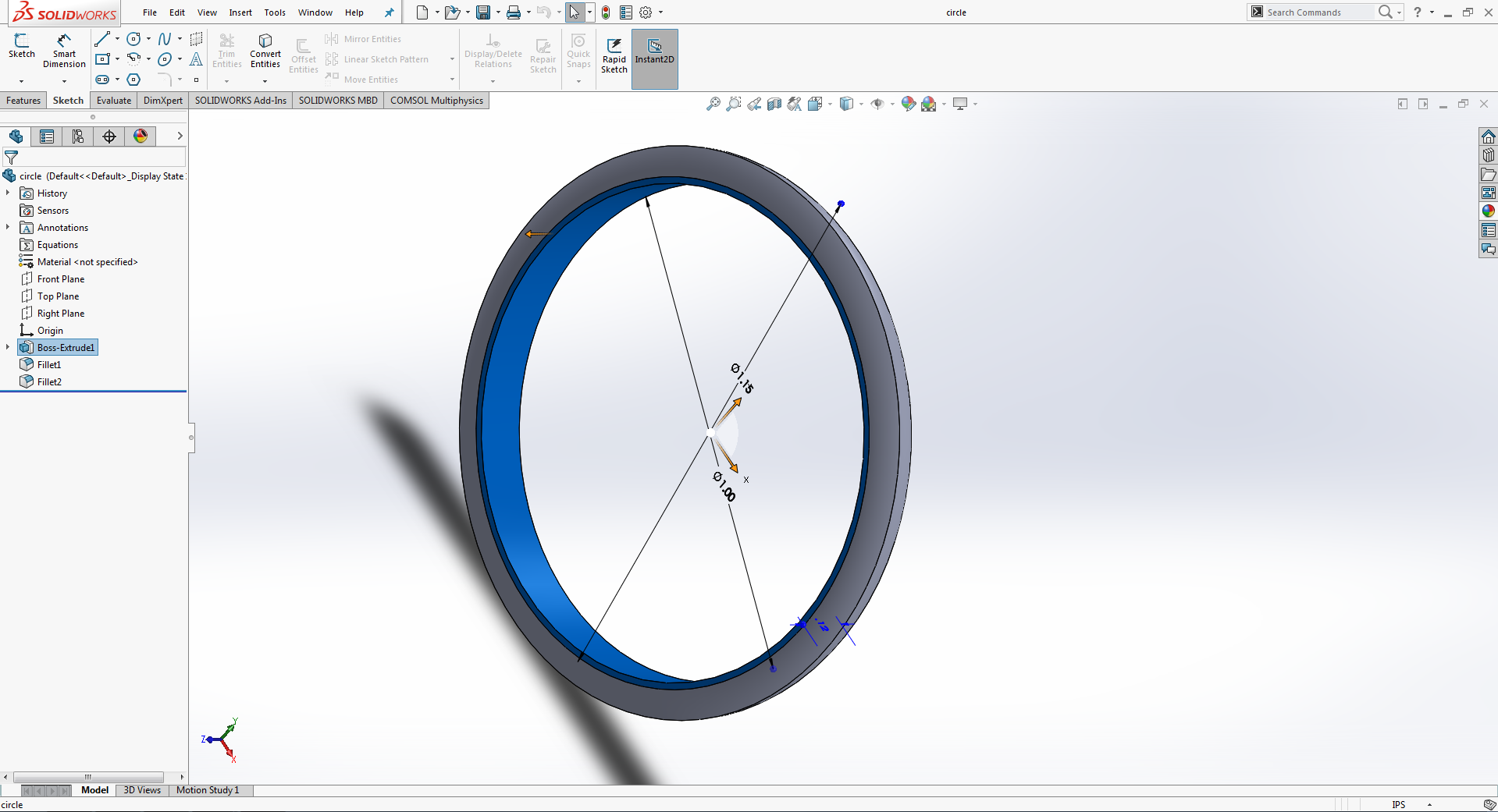
My one part is remaing i am going to put rings inside the joint sticks so it becomes some additive.
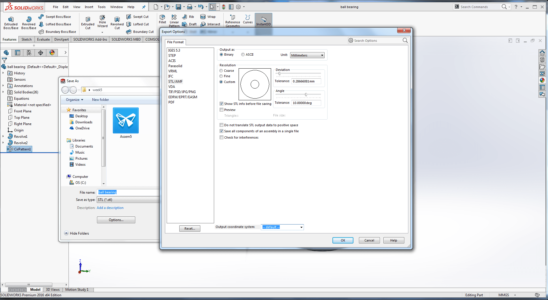
Now save as .STL and go to option s and tick on save all components of an assembly in a single file and then press ok.
Cura
Since I am using an Ultimaker I decided to use their slicer Ultimaker Cura. Cura has premade printing settings that get good results without even knowing much about them.

Open the .stl file left 1st option is for drag the design in x,y and z axis
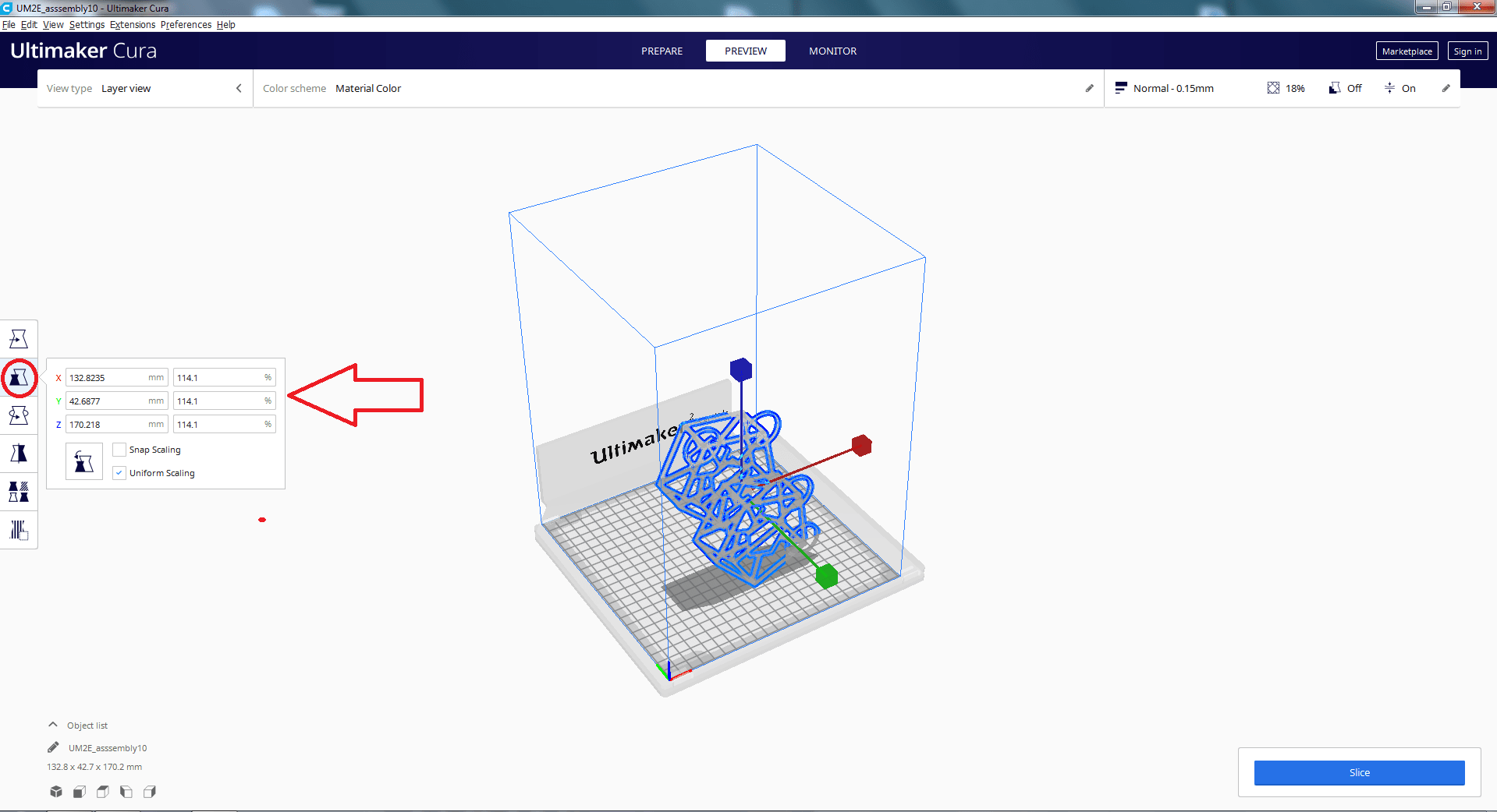
Then, using the scaling button, I downsized the item to have lower dimensions.
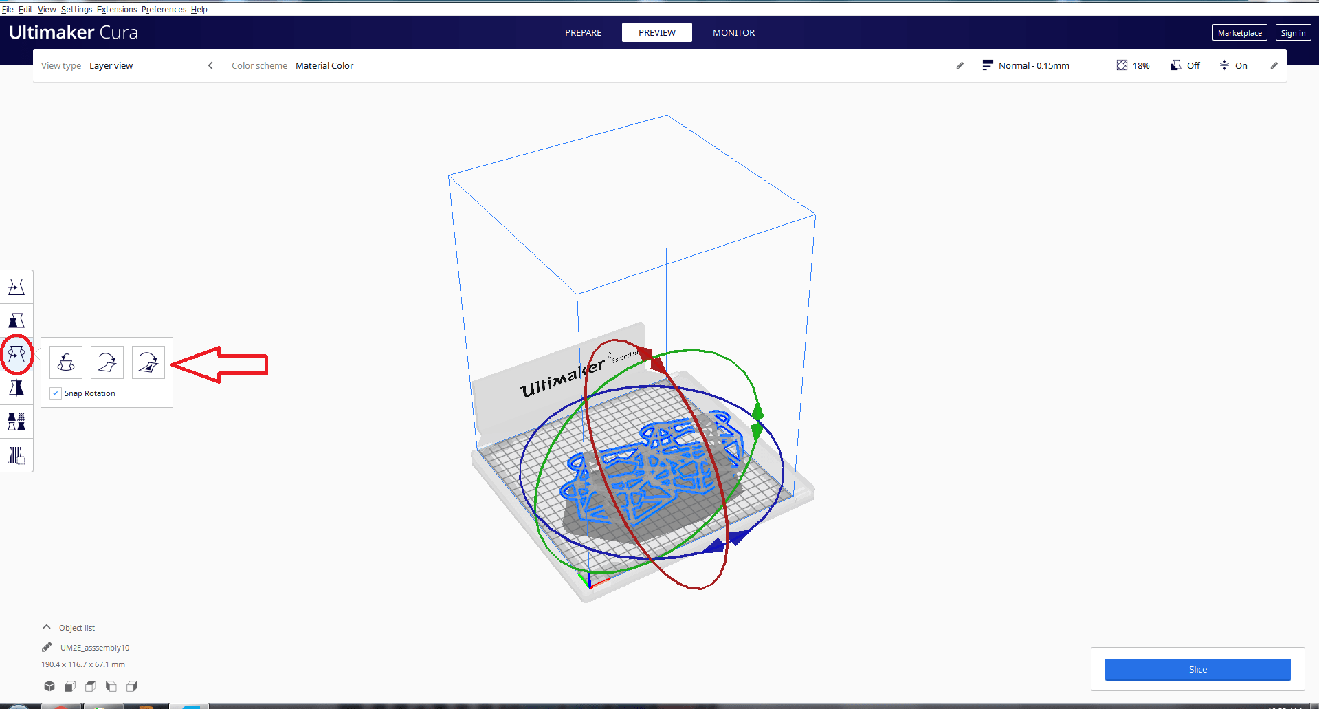
In this option we can change the axis of object
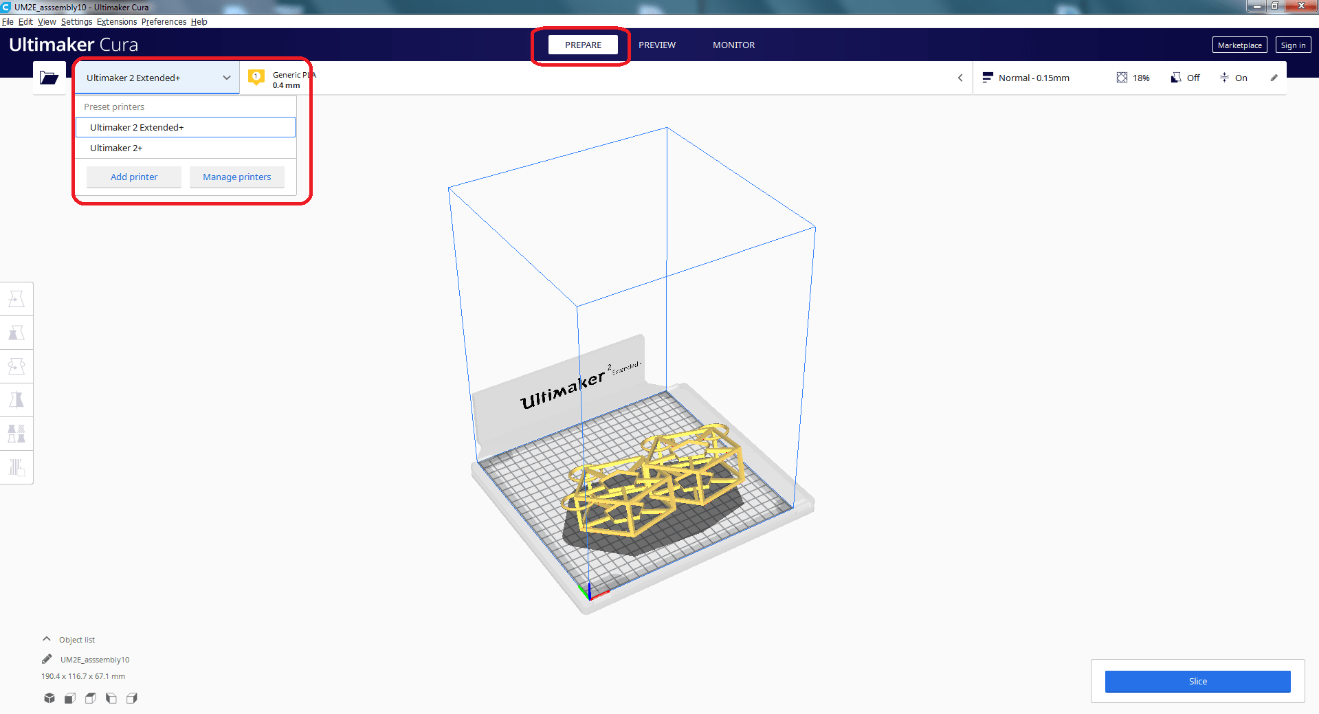
The printer that you are using can be selected from the top left option.
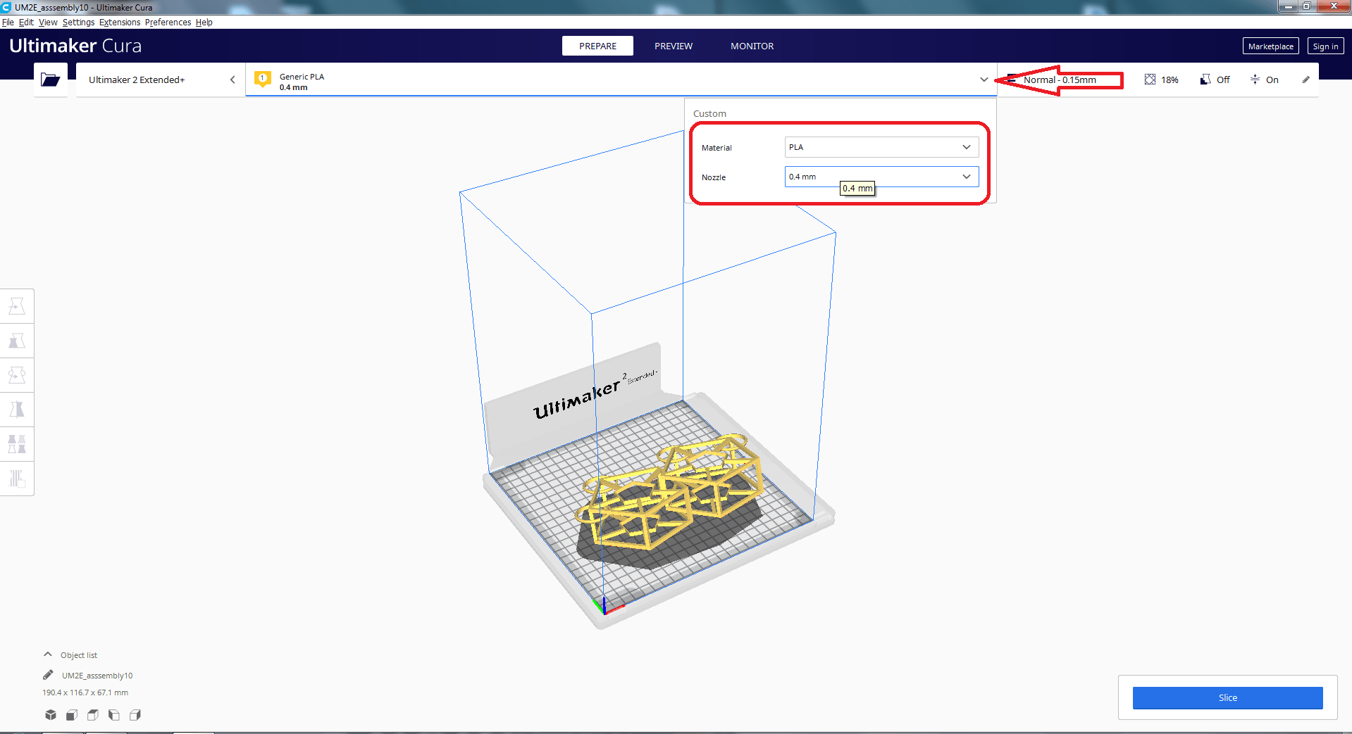
Add Ultimaker 2 Extended+ printer, then choose from material Generic > PLA or Ultimaker > PLA
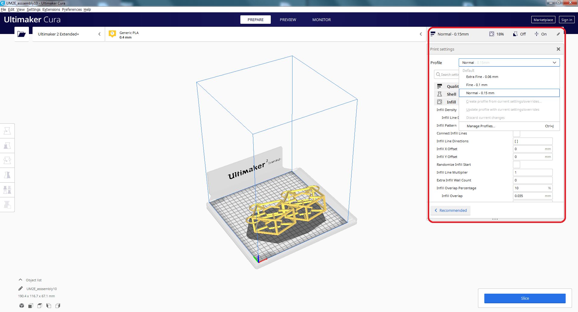
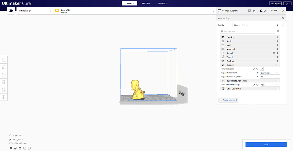
There are several options on the right side of the column where the user may specify the quality they desire.
I changed the density and arrangement of the infill. I may modify the different parameters of the infill depending on the design.
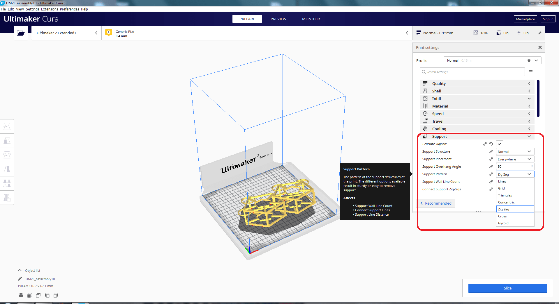
I set pattern of support
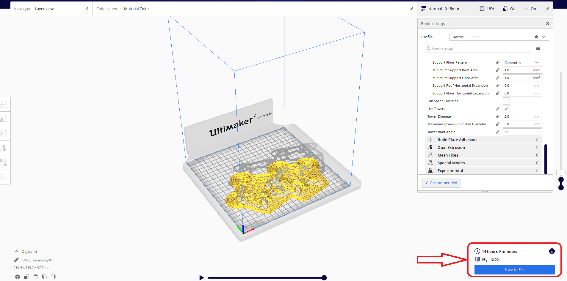
After slicing, the time necessary to finish printing is shown.
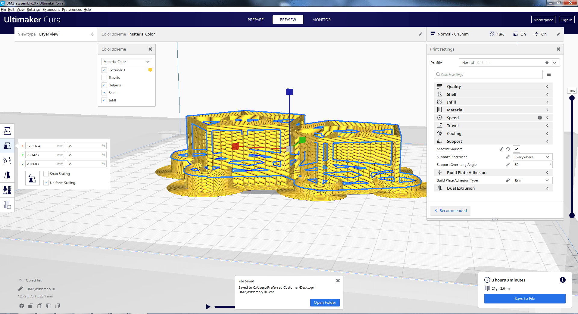
Give support zigzag and set some more settings with respect to my design.click on slice then save as .gcode format.
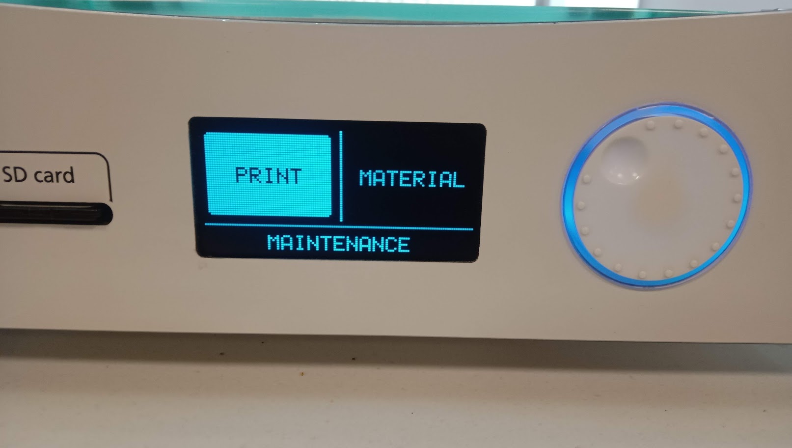
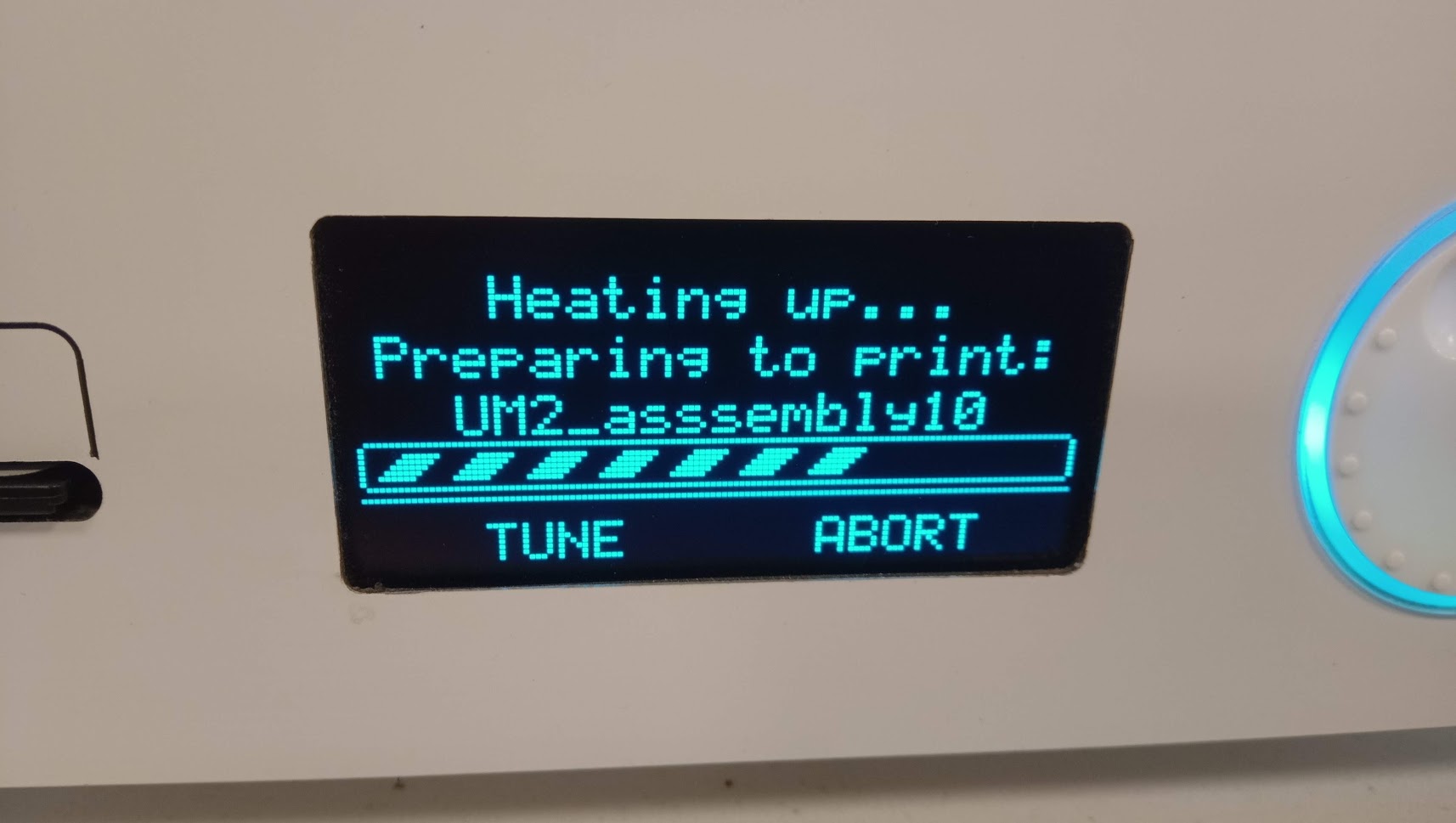
Now click on the print and then select your file press ok.
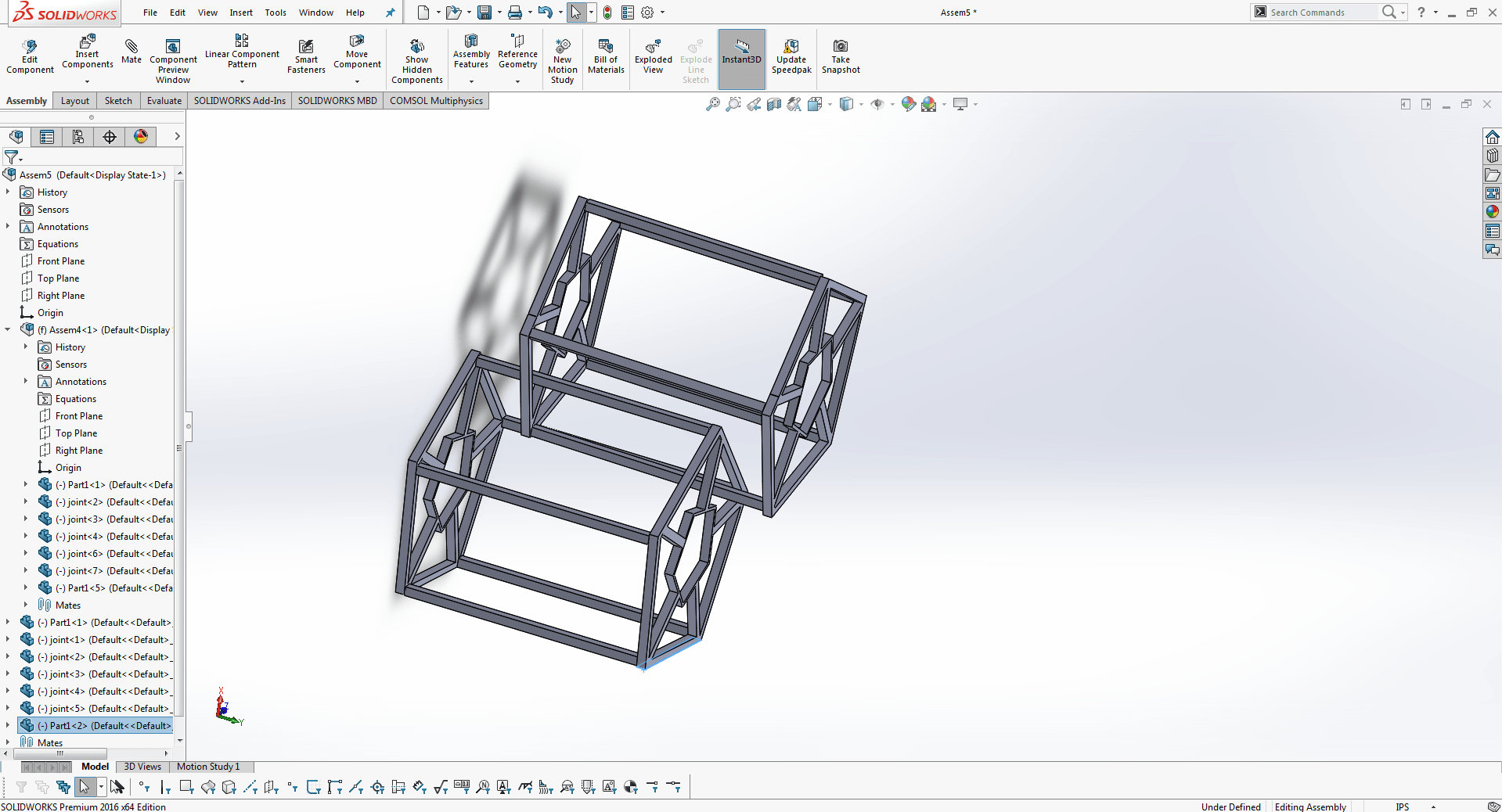
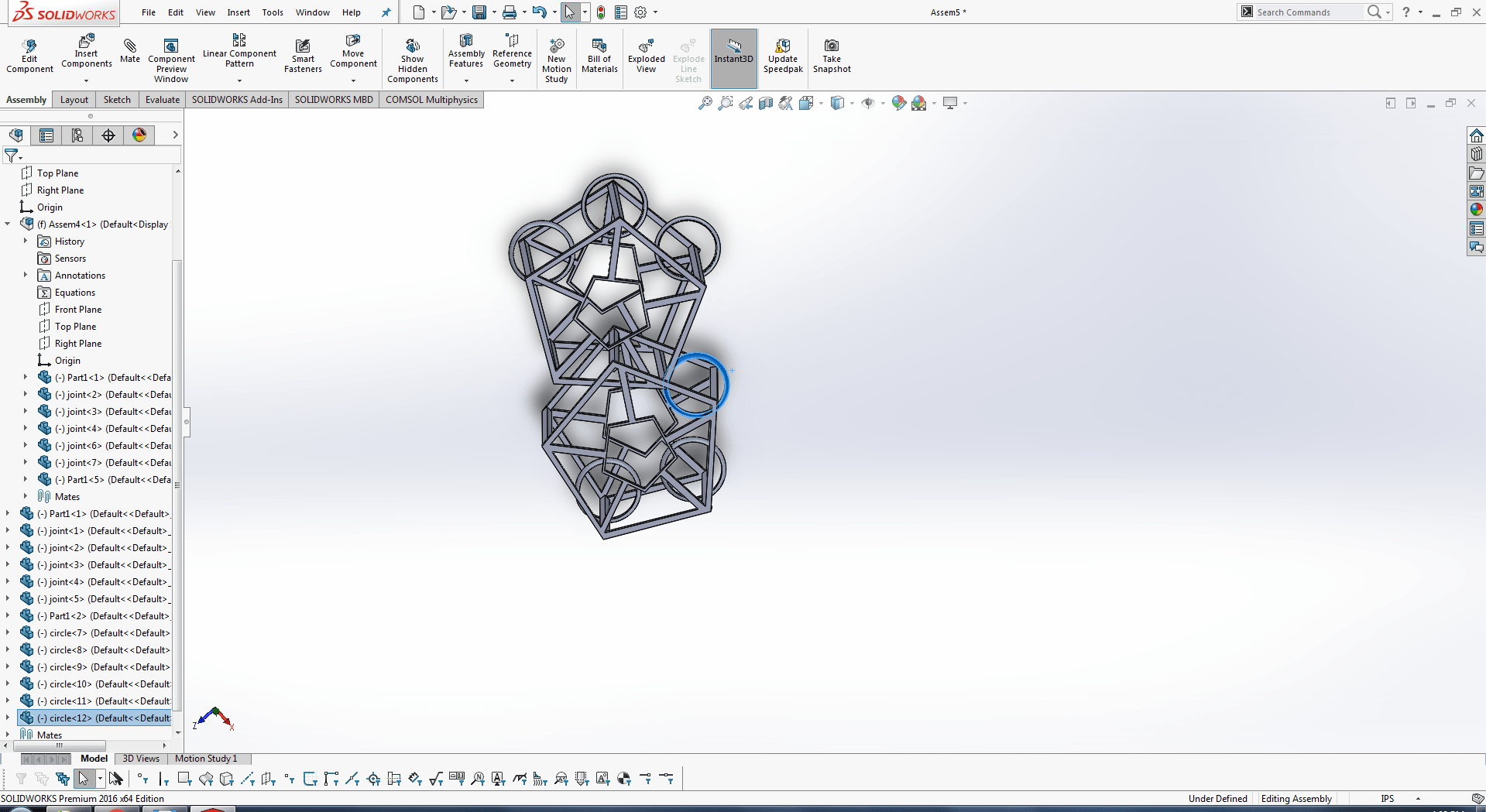
My one remaining part is that I am going to insert rings within the joint sticks..
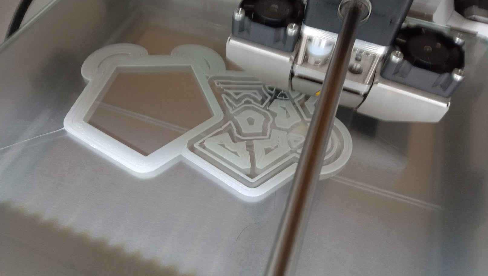
It creates support from the cura software that I pick. It's printing well.
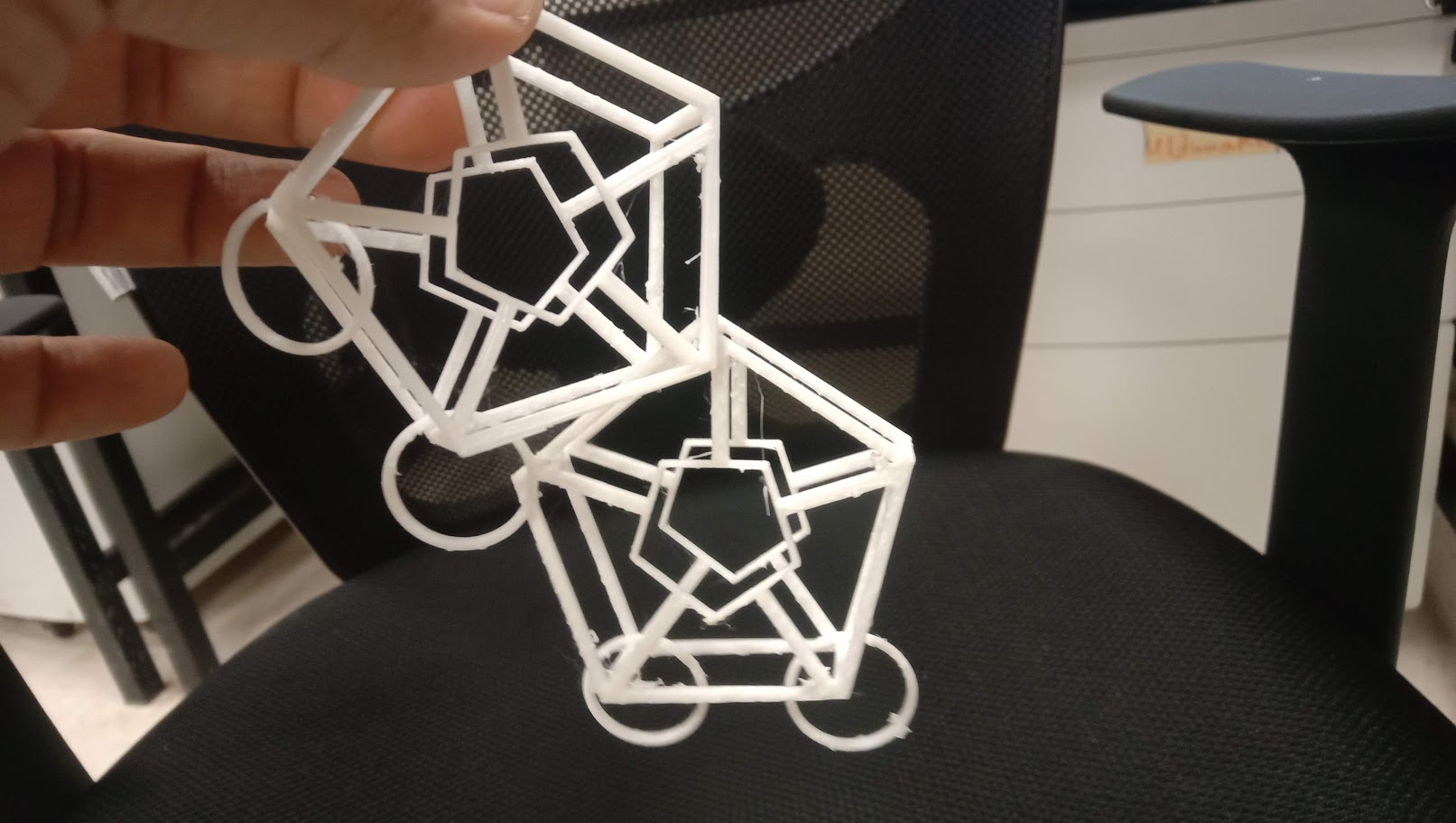
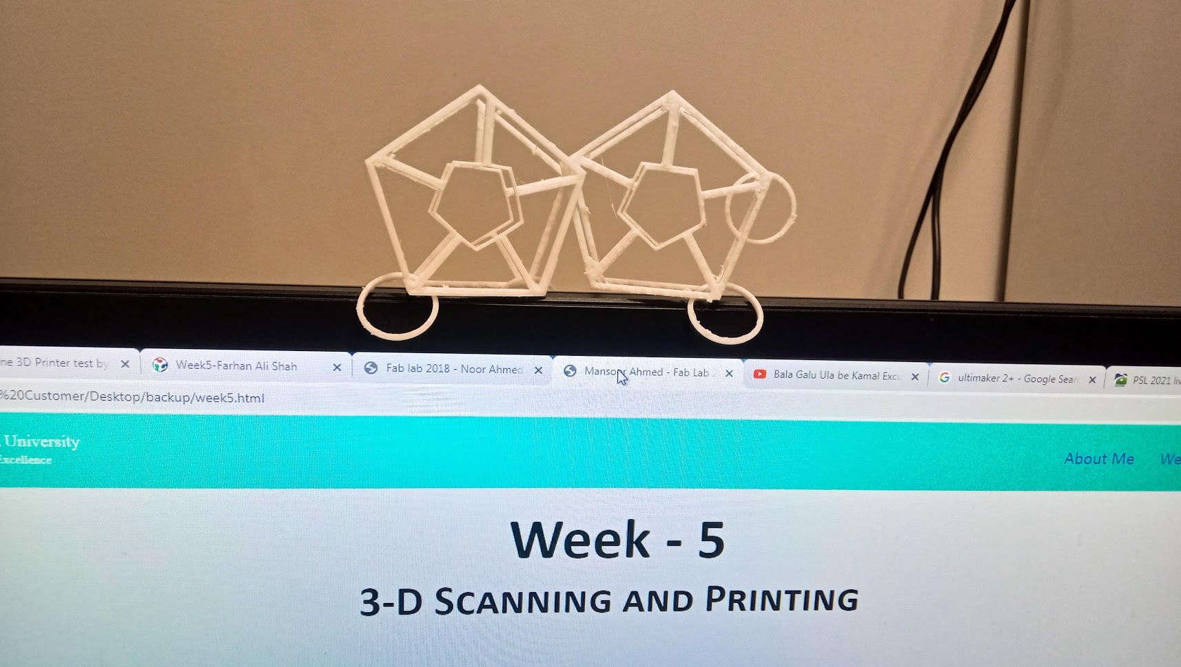
This is my final 3D printed concept result; it is additive; the four circles can revolve, as can the two pentagonal shapes. It is also additive, and I have it on my computer's display as seen above.
3D SCANNING
The technology of 3D scanning has always been out of reach to the consumer because of expense and complexity.
In our fablab, we have faculity to use two type of 3d scanners which are Xbox Kinect and sense.I used both of them.
SENSE 3D Scanner
For the sense 3d scanner i used software 3D Systems Sense.It is very handy software there is no any need to watch tutorials.
Before scanning I would like to know about the specifications of the scanner. I wanted to do is to make sure that my scanning object is falls within the limit. As well as I wanted to have some more information about 3D scanning how it is done and what are the majors to be take care of while scanning object.
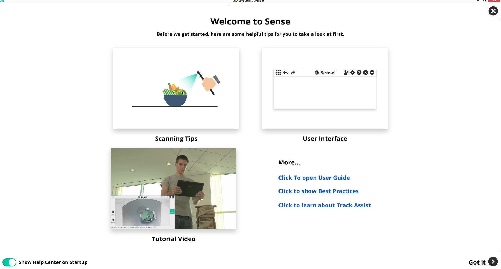
This is the software's default browser, where you can see the manual and tutorials. I just clicked on got it.
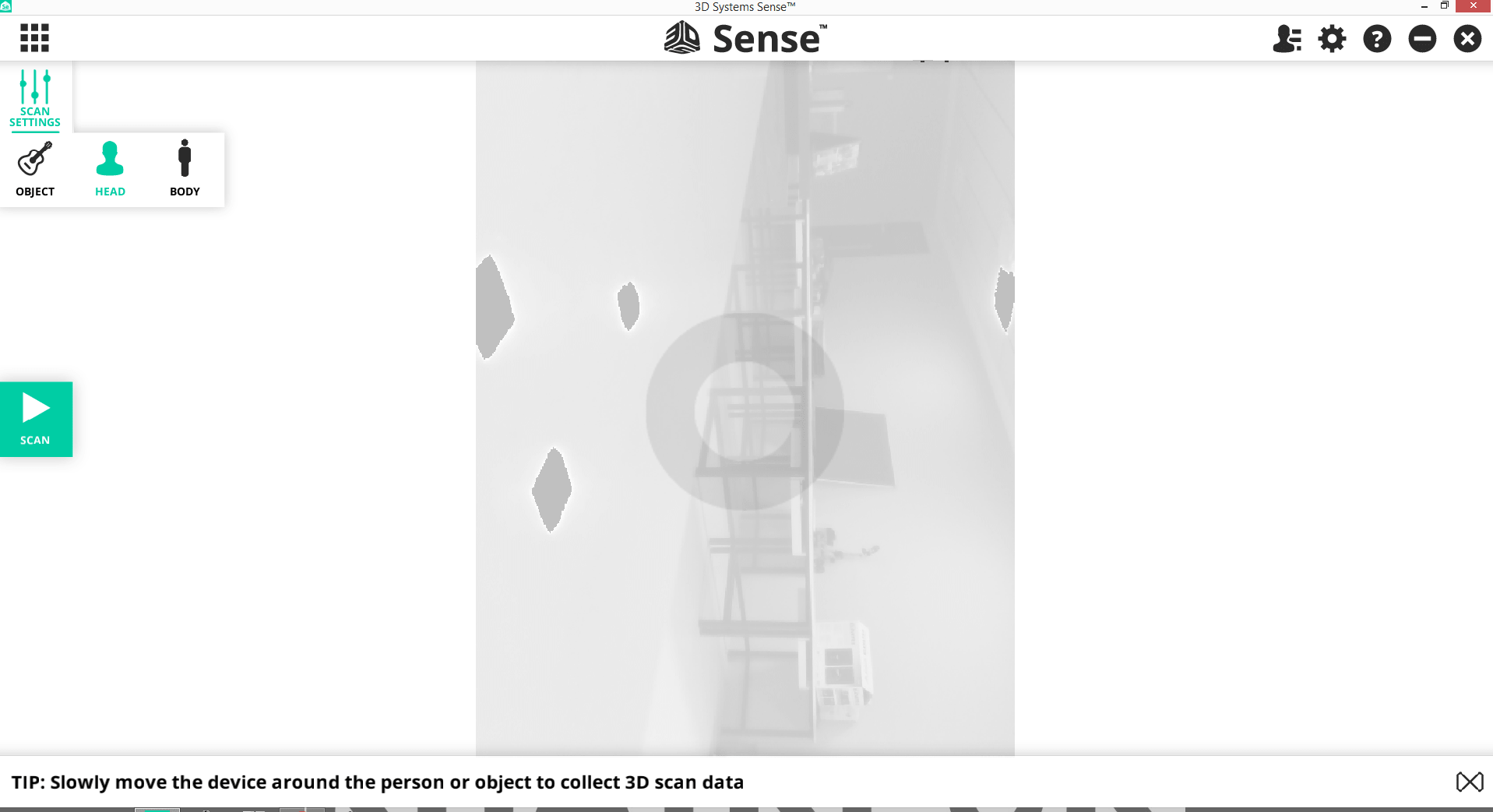
Now this window is open. Select the setting which thing you want to scan i click on on the body it can be change by the requirment as object or body.
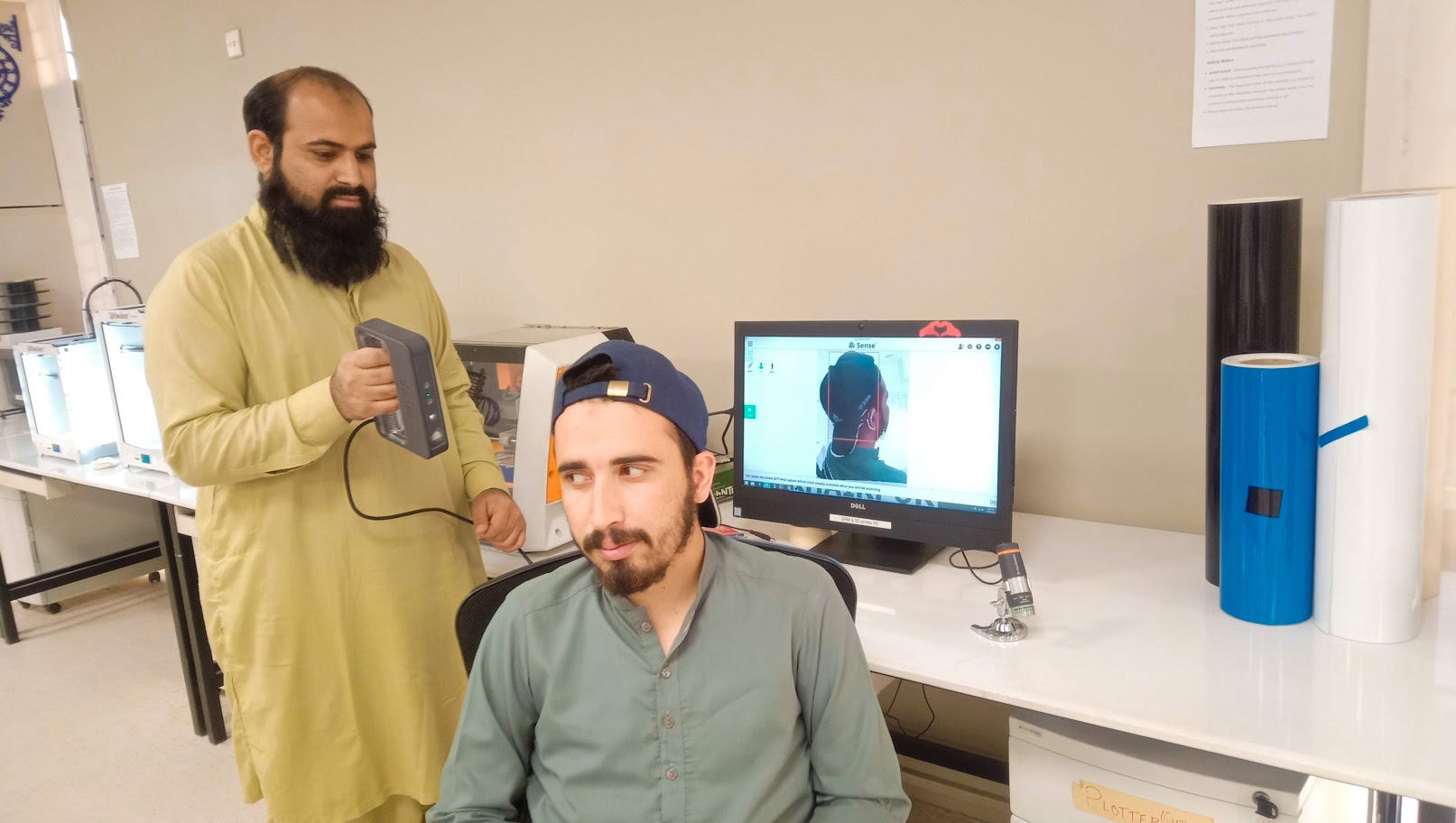
I am scanning my friend.I hould the scanner and my friend is revolving him self around the same axis.
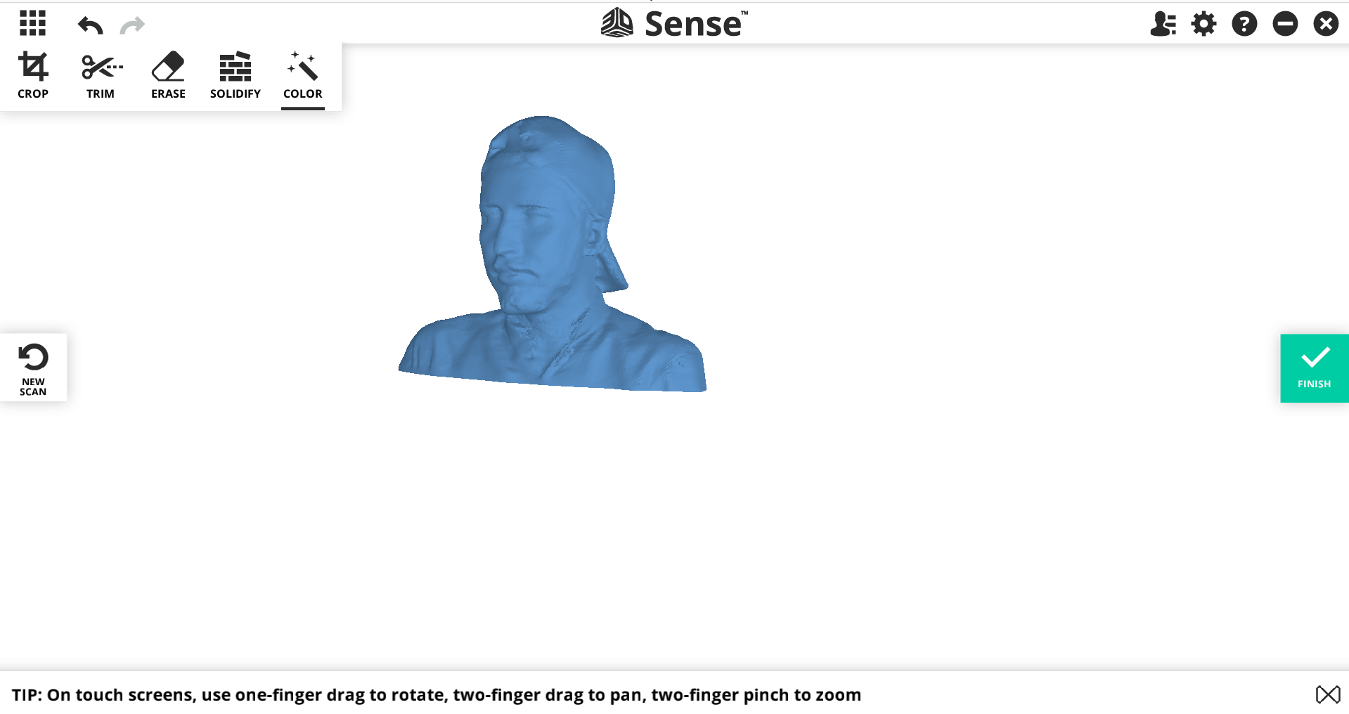
Here is the result of 3d model which was hollo i select the option of solidify and also remove extra lines.After all these steps result is takken.And save file in the format of .OBJ
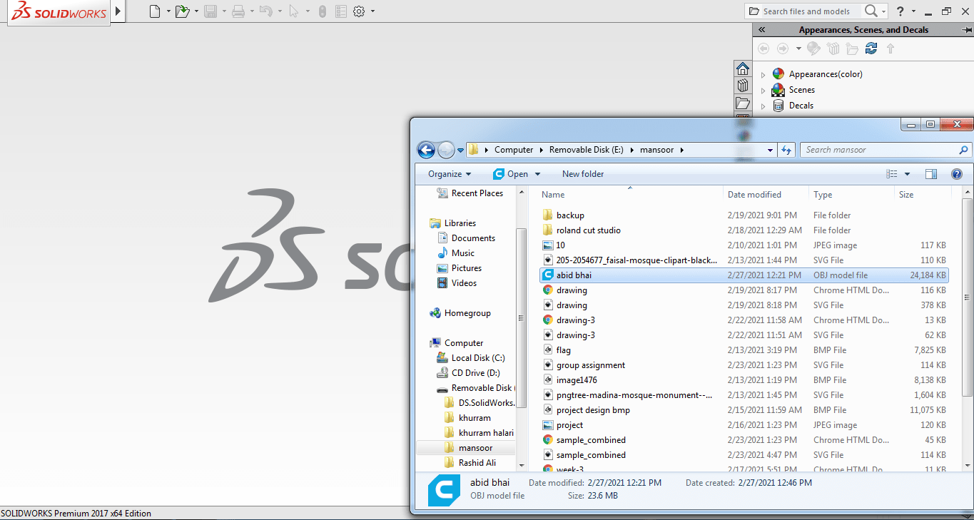
Now i am going to open solid work which can read that format.
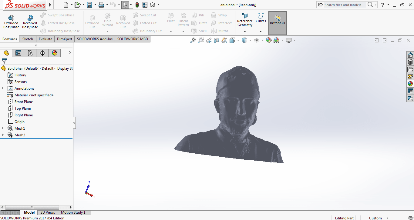
Now it's time to convert .obj into .stl format and save the file which can be open into the cura software.
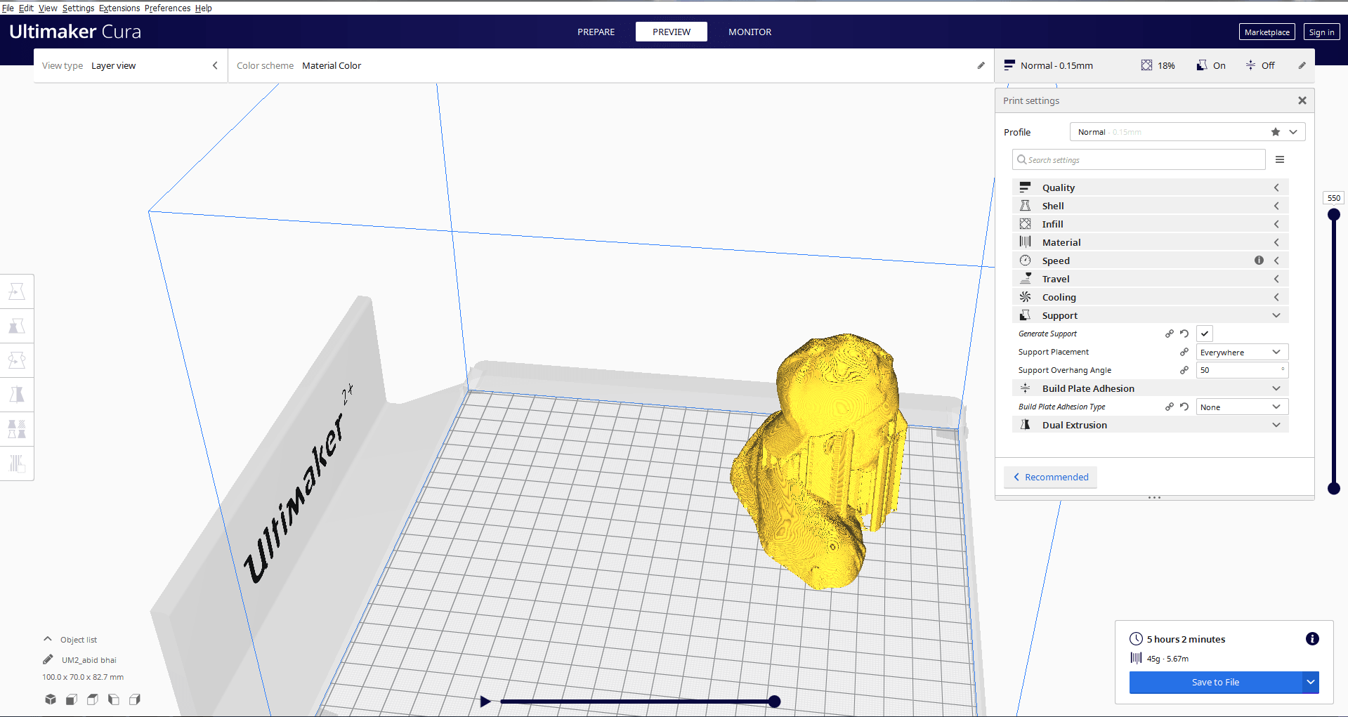
This is the preview of the model and it is ready to print.
Select your printer, change the object size, set infil material and make slice and save that fil as gcode format this file model in ready to print it through 3d printer but it's optional step so i am not going to print that model.
Xbox Kinect 3D Scanner
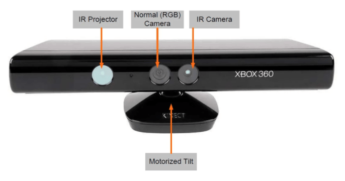
This is the well nown scanner which is mostly gammers like this.This 3d scanning technique uses an off-the-shelf Xbox Kinect and free software to create 3d models easily.
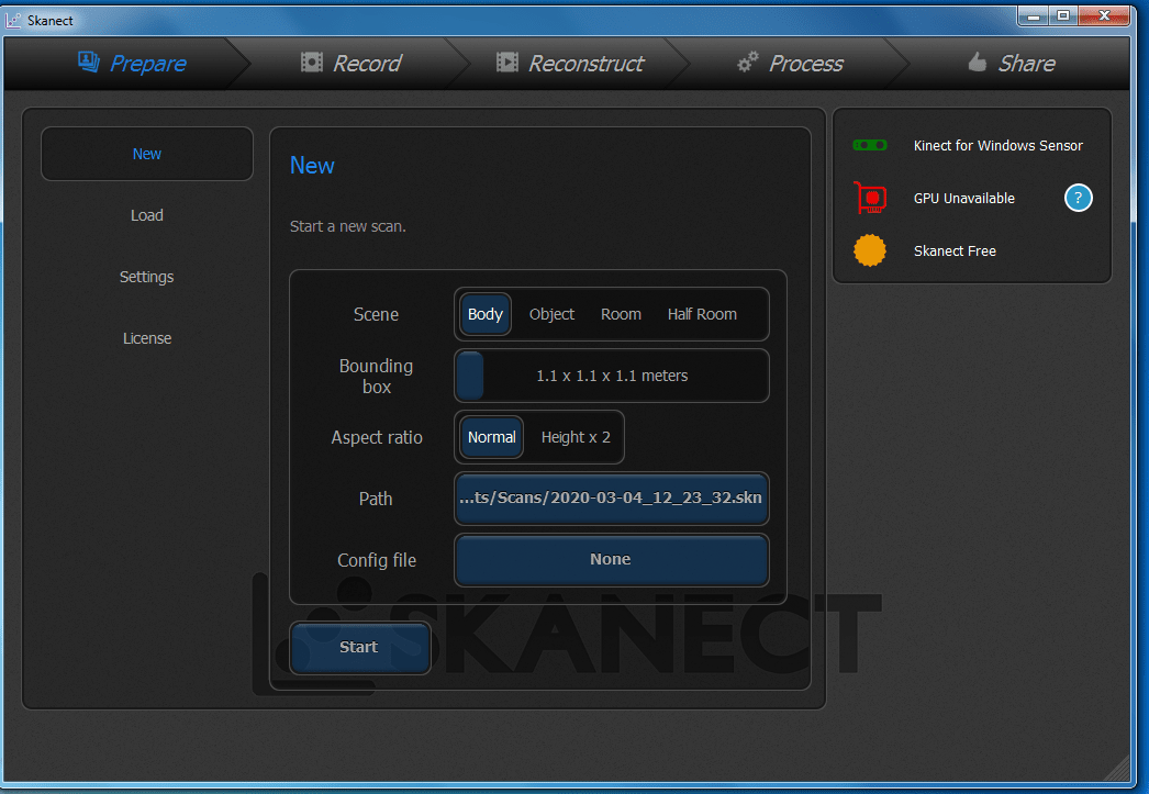
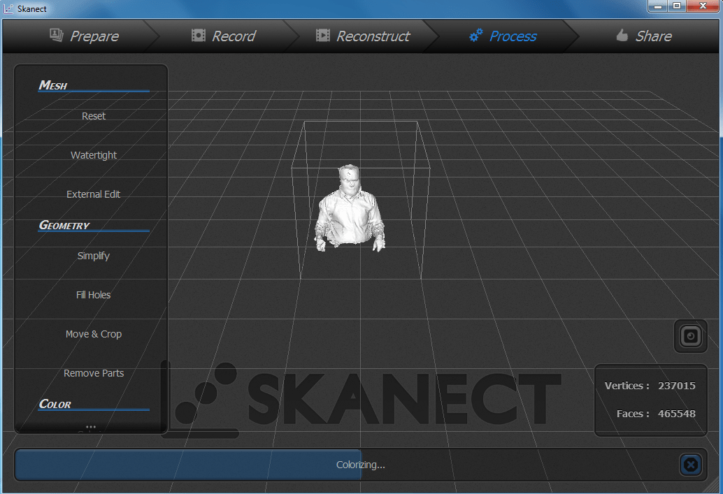
Now, i am using Kinect Scanner and install the Skanect Software and its Supporting tools for the Scaning.Now this time I am going to scan myself Connect the 3D scanner with Pc.
The software was pretty simple to use and didn’t require any tutorials, Once the program was started the software looks for any connected scanning devices. Then you can create your new project by clicking the new button. This offers a variety of options that you can select depending upon the nature of the scanning. I used Kinect as a scanner.
After opening the software click on the Record button(red button). Move slowly and precisely to record video, stop and wait if the red color comes on screen.
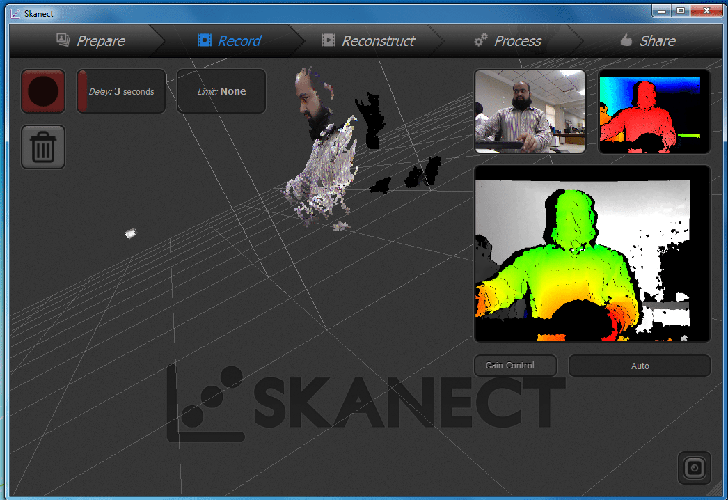
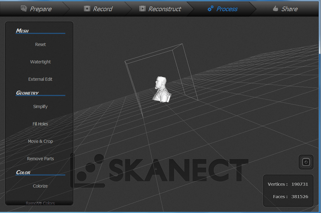
Press the red button when circular scanning is complete, After processing the result will be shown:
Now there are some missing parts its a hollo type for fill these hollo part click on fill the holes.
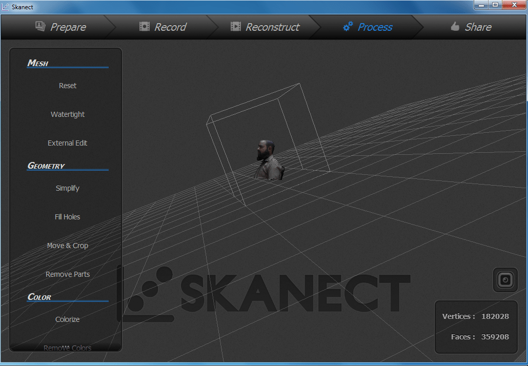
Now model is ready to save.
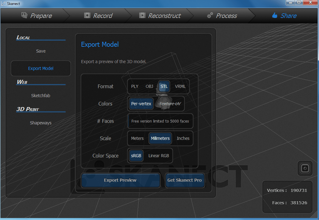
In Share tab select.STL as format and scale as millimeter and click on export preview and save it
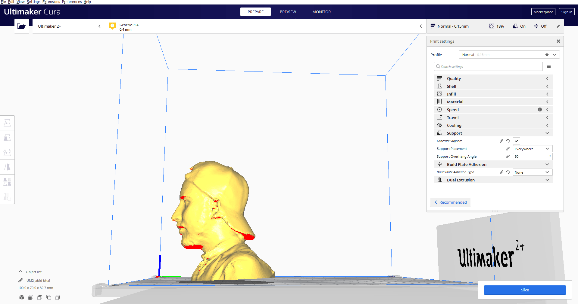
Now open this STL file into Cura software and align the settings concerning the printer and then make slice save this file into the .gcode format which 3rd printer can read this format.
"Click here"to download all files of this week