
|

| Sukkur IBA University Merit, Quality, Excellence |
Week - 3
Computer-Controlled Cutting
Assignment
Group Assignment
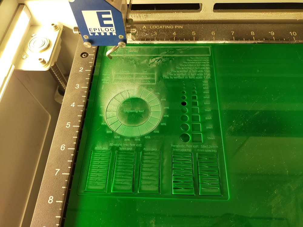
characterize your laser cutter, making test part(s) that vary cutting settings and dimensions.
Laser cutting techniques
Laser cutting is a technique in which a laser is used to cut or engrave material using computer-controlled parameters. The laser is very effective and precise, focusing on a specific region of the object. Plastics, woods, rubbers, foams, sheets, acrylics, garments, and even metal can be sliced with the laser. When you use your laser cutter, you have complete control over the beam. This means you can monitor the heat output of the beam, as well as the strength and length of the beam on your material. A laser cutter may be used to execute a number of different procedures.
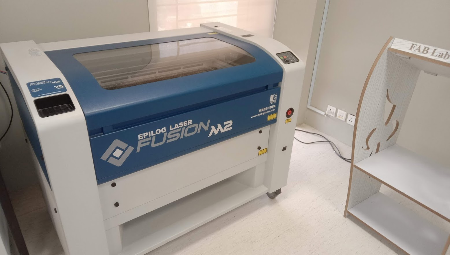
Epilog lasser fussion M2 machine is used in our lab.
Laser Safety Precautions
Never leave the machine unattended. Only cut materials that you can cut with the laser cutter. If you are not sure ask someone. Never forget to turn on the air compressor/filter, otherwise you might destroy the laser. Moreover after finishing a job wait for a bit before you open the lid. Make sure you know what to do in case of fire. We must set the target and the jog after turning on the unit and the air compressor/filter. On the menu screen, choose jog. To move the laser, use the joystick. To see where the laser begins, press the (star) lightning button, and a red laser pointer will appear. Push the joystick to ensure that you've switched to the correct jog place.
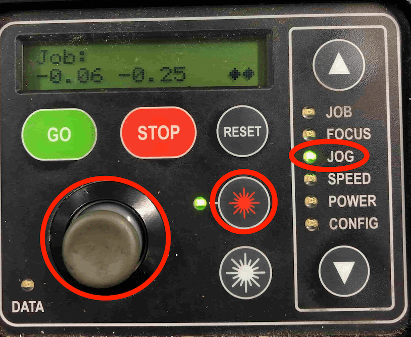
Now select focus on the menu panel. Use the joystick to move the surface. In addition use the triangle to measure the focus.
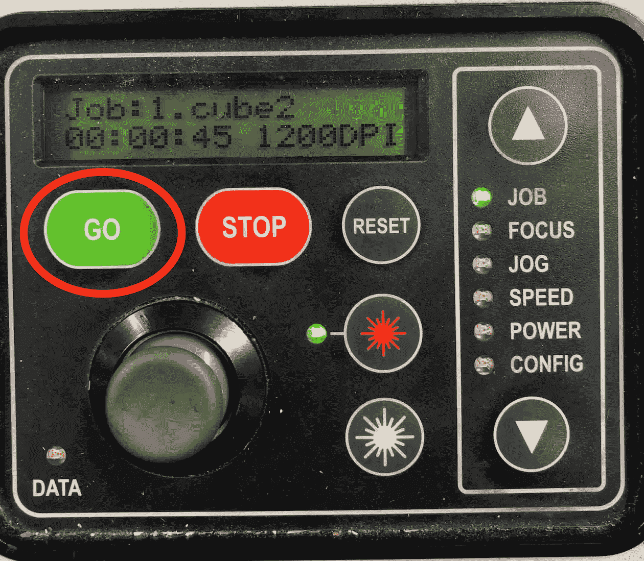
Press go machine will start cutting
Procedures for Using a Laser Cutter
Cutting line strokes were set to 0.001 inches per the instructions. But for 0.001 cm, the other vectors are set to engrave with respect to their greyscale hue. Then we transform our SVG file to PDF, setting the page size to 32x20 inches in paper properties and rasterization resolution to 600 dpi.
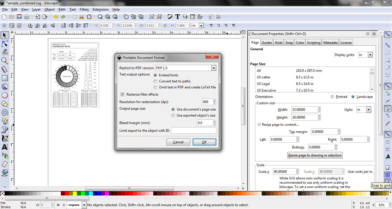
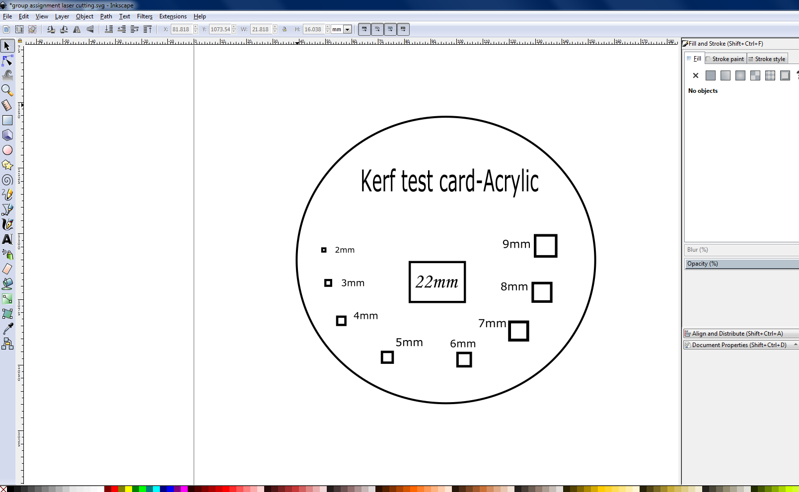
creating an svg file and converting it to pdf
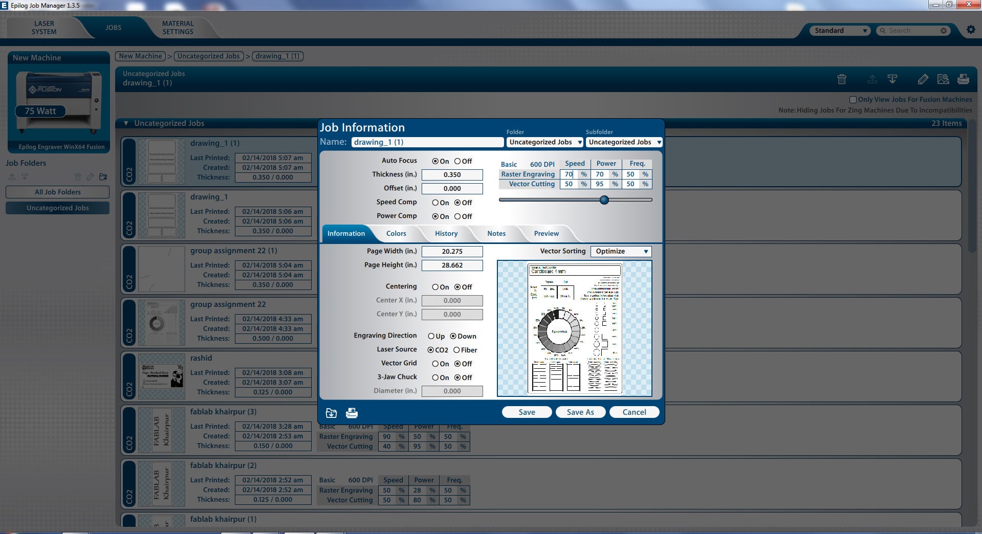
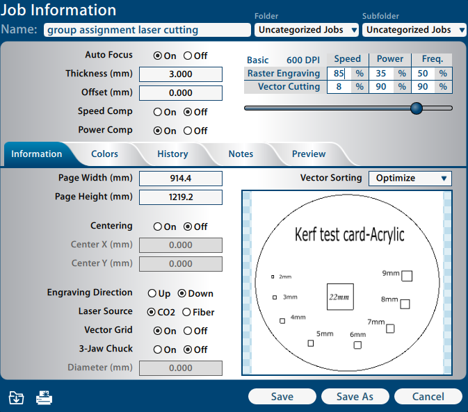
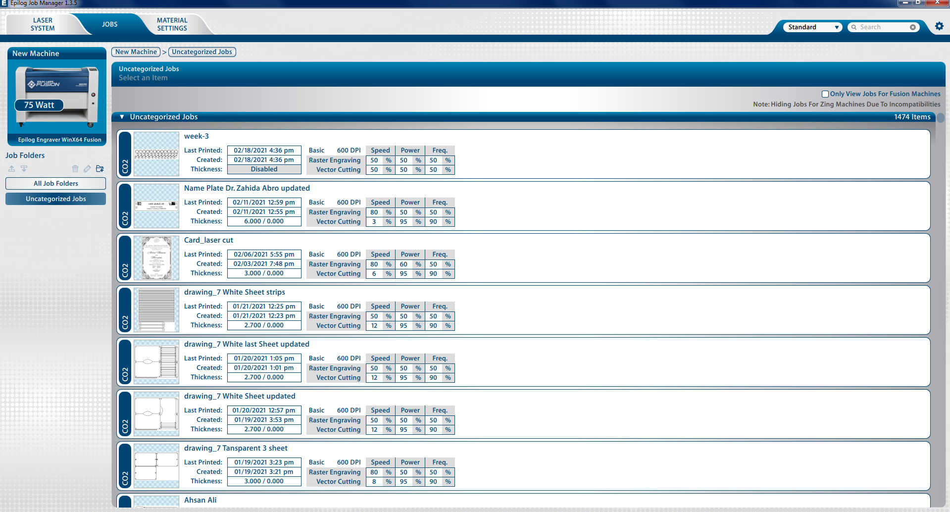
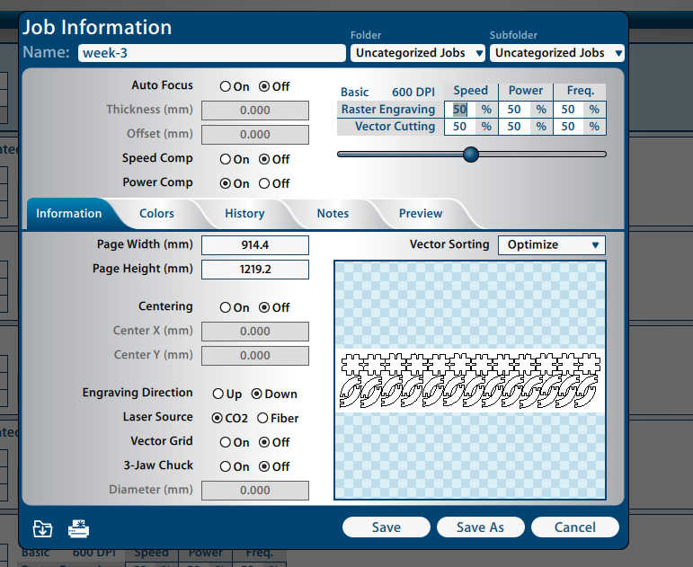
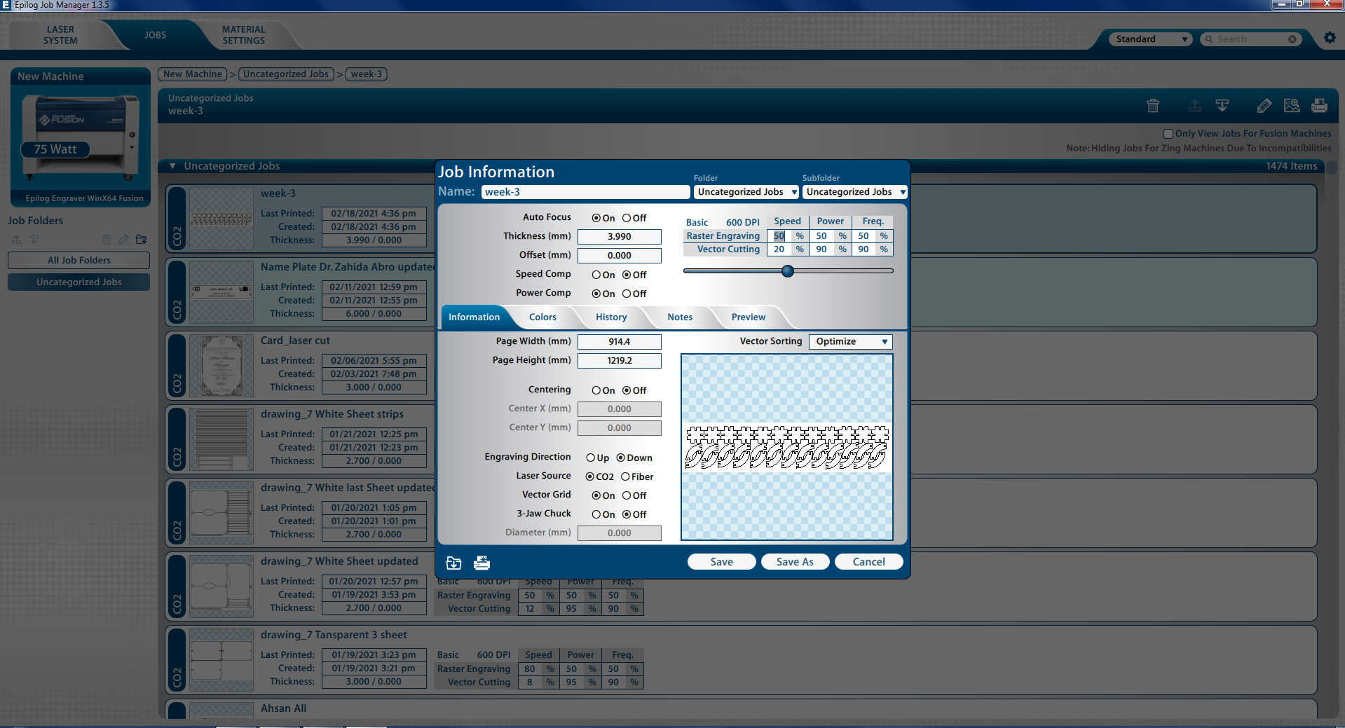
Job information in Epilog Job Manager
After choosing the location, press "Save," and the new details will be saved in the job. To move the job to the laser cutting system, click "Print" (top left corner in Epilog Job Manager).
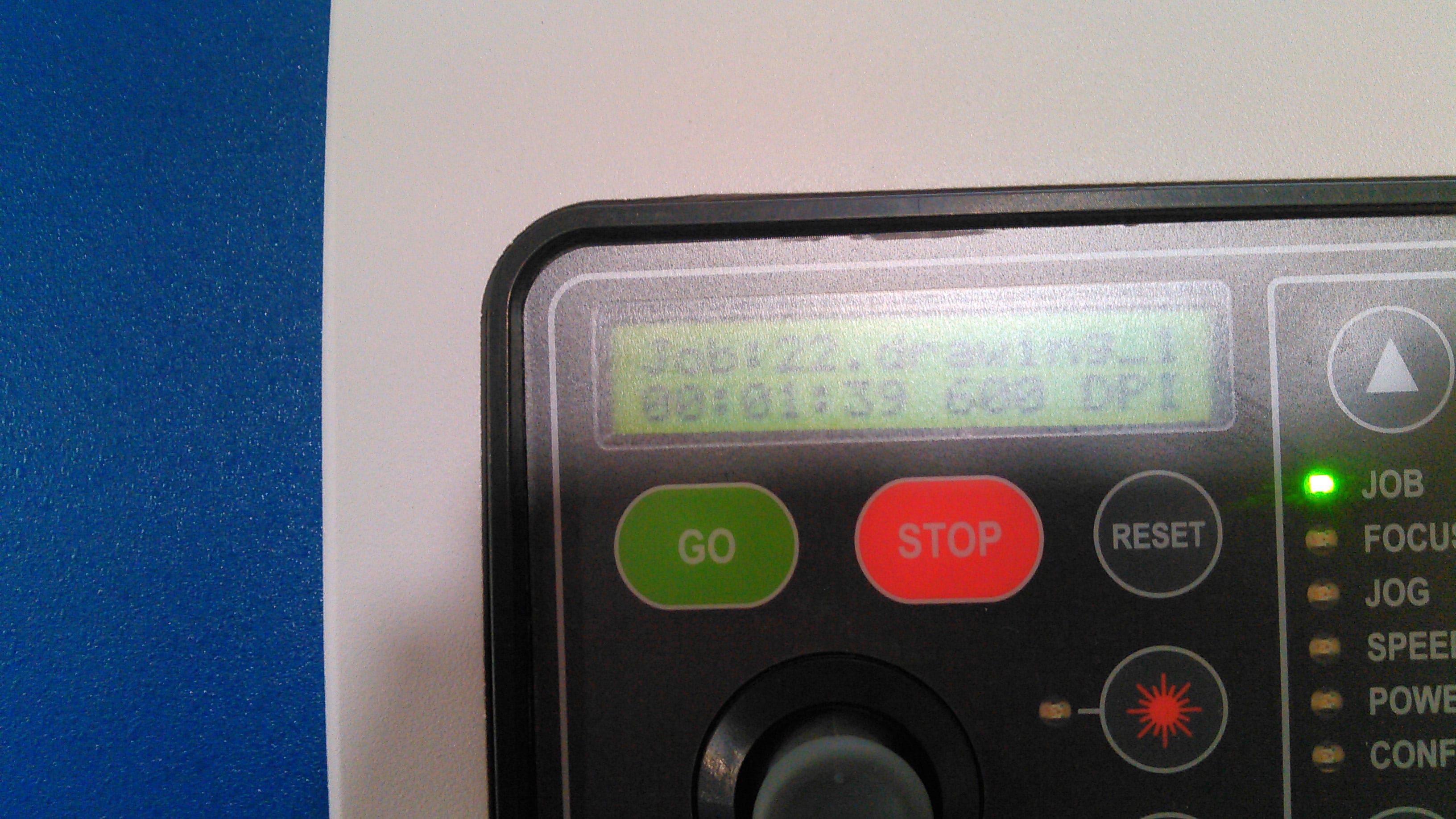
Display of job information on Laser Cutting Machine panel
From this group assignment we learn that after all process and operation laser cutting machine is based on 2 things laser power and speed. We have to set the exact ratio of power and speed for engrave and cut which is based on material thickness and material type. More power with slow speed can burn the material and fast speed with low power can engrave but it maybe lighter enough to do job again.
KERF TEST
Kerf is the width/thickness of a cut made by the cutting tool as it cuts through different material such as wood, cardboard, acrylic, etc. The material removed during cutting. It is important to know the kerf so that the pointer of the cutting process (laser, water jet, etc.) can be slightly offset to allow for it.
Measuring The Thickness
Working In Inkspace
EPILOG SETTING
The thickness should be defined when designing the file to be laser cut.
TESTING KERF IN DIFFERENT SLOTS
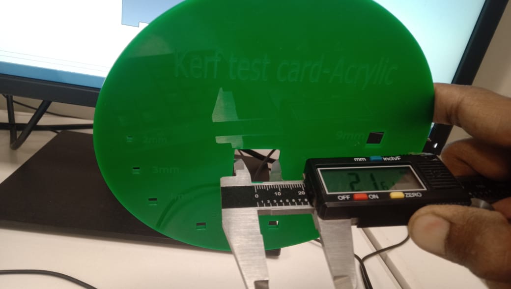
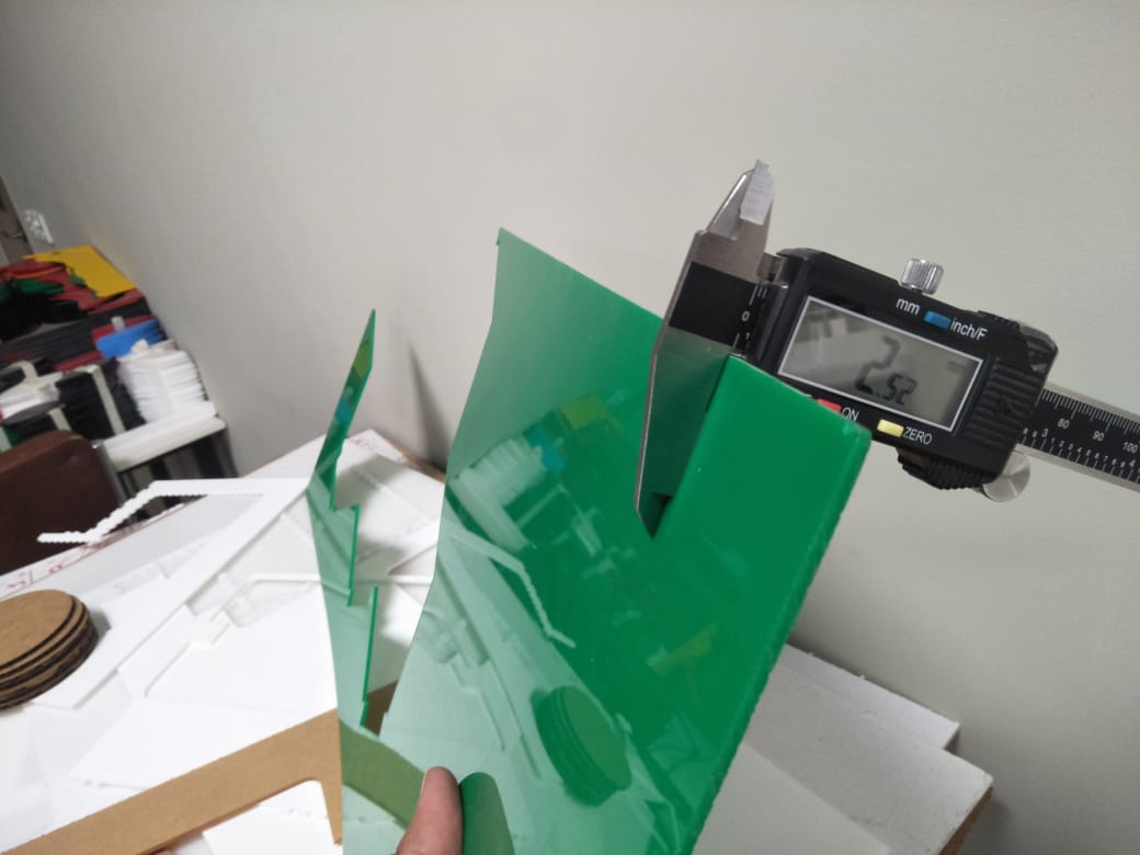
We measure the 22mm box using vernier caliper after laser cutting. Due to material burning during laser cutting, there is a 0.4mm gap.
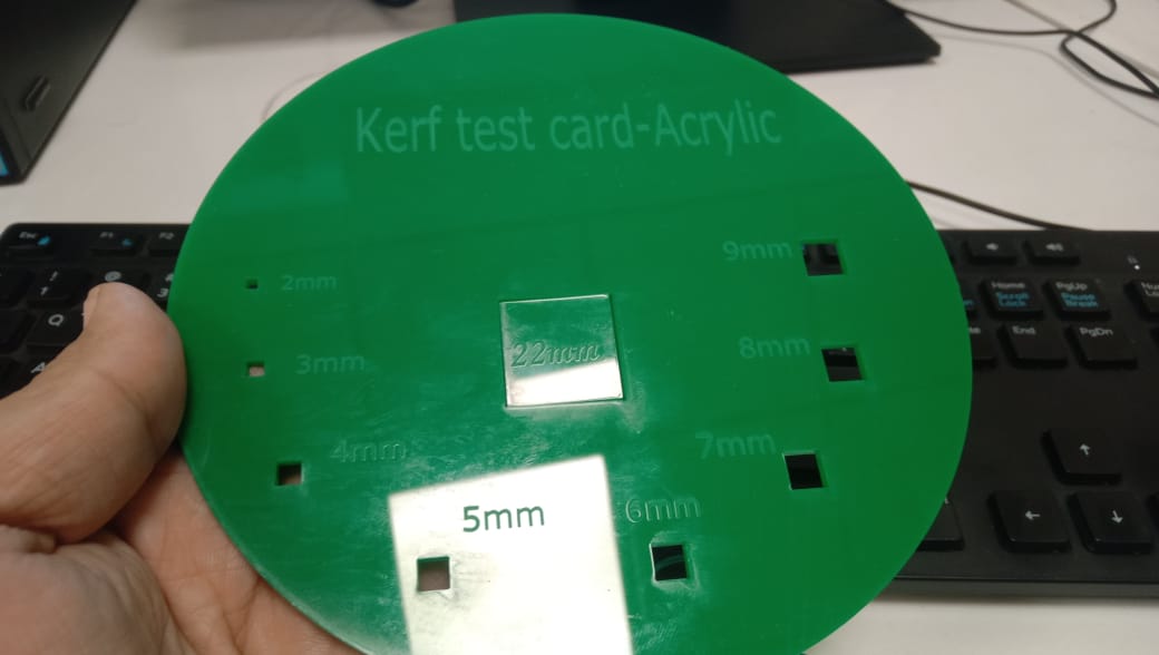
A 22mm piece of material is easily fitted into the kerf card box, which shows the laser's burning effect on material.
Individual Assignment
Cut something on the vinylcutter.
Design, make, and document a parametric press-fit construction kit using lasercutter.
Accounting for the lasercutter kerf, which can be assembled in multiple ways.
Individual Assignment
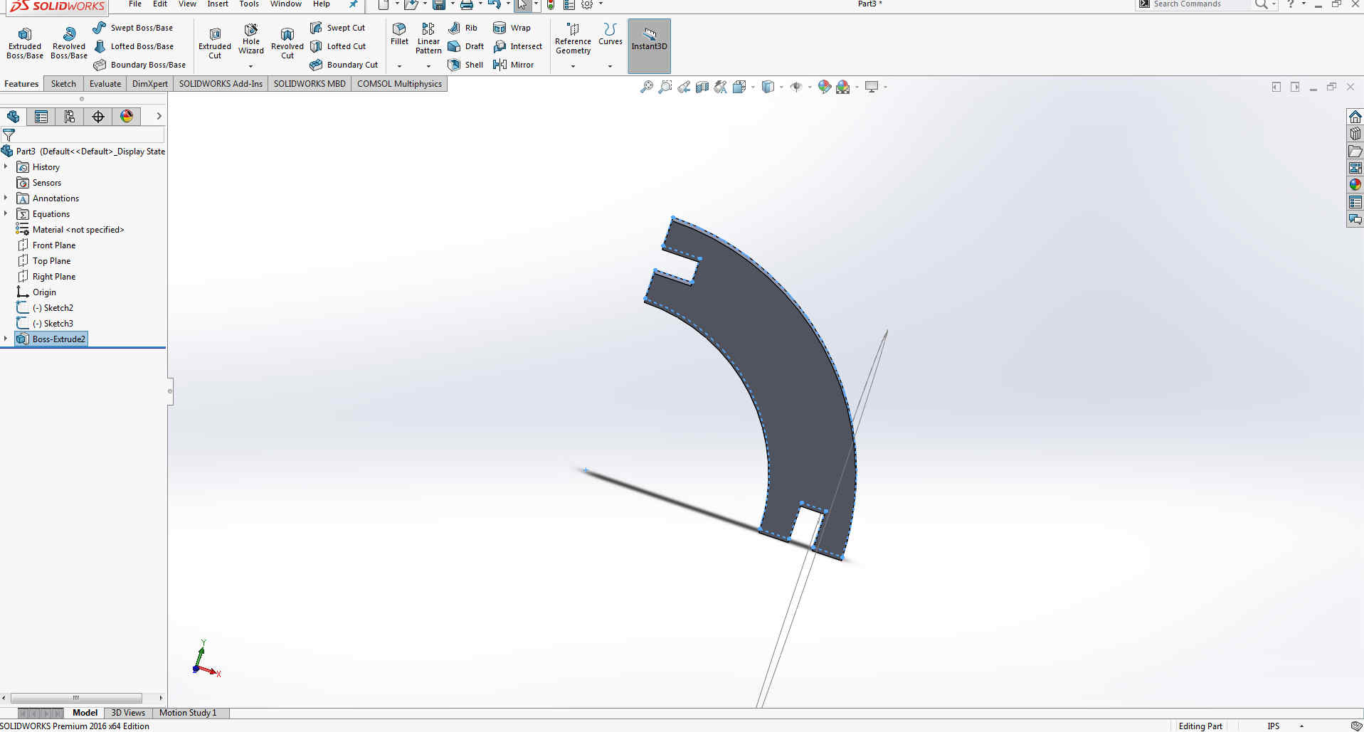
For the making of my 3D Model of part, I have decided to work on SolidWorks.My model consists of two different parts which can be assembled to make 3-D models. I will be making this model as a parametric press-fit kit which means the model will be based on equations. Whenever I want to change any kind of parameter I will change that for example I have will use 4mm thickness of cardboard which I can replace with 16mm or any other thickness. I can also reduce the hole size of my model. So firstly we start with selecting "Part".
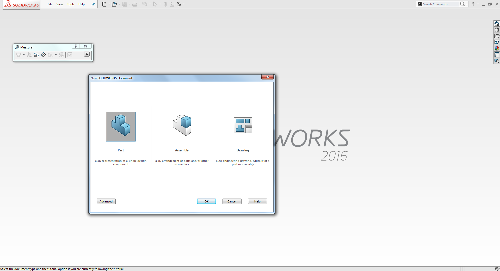
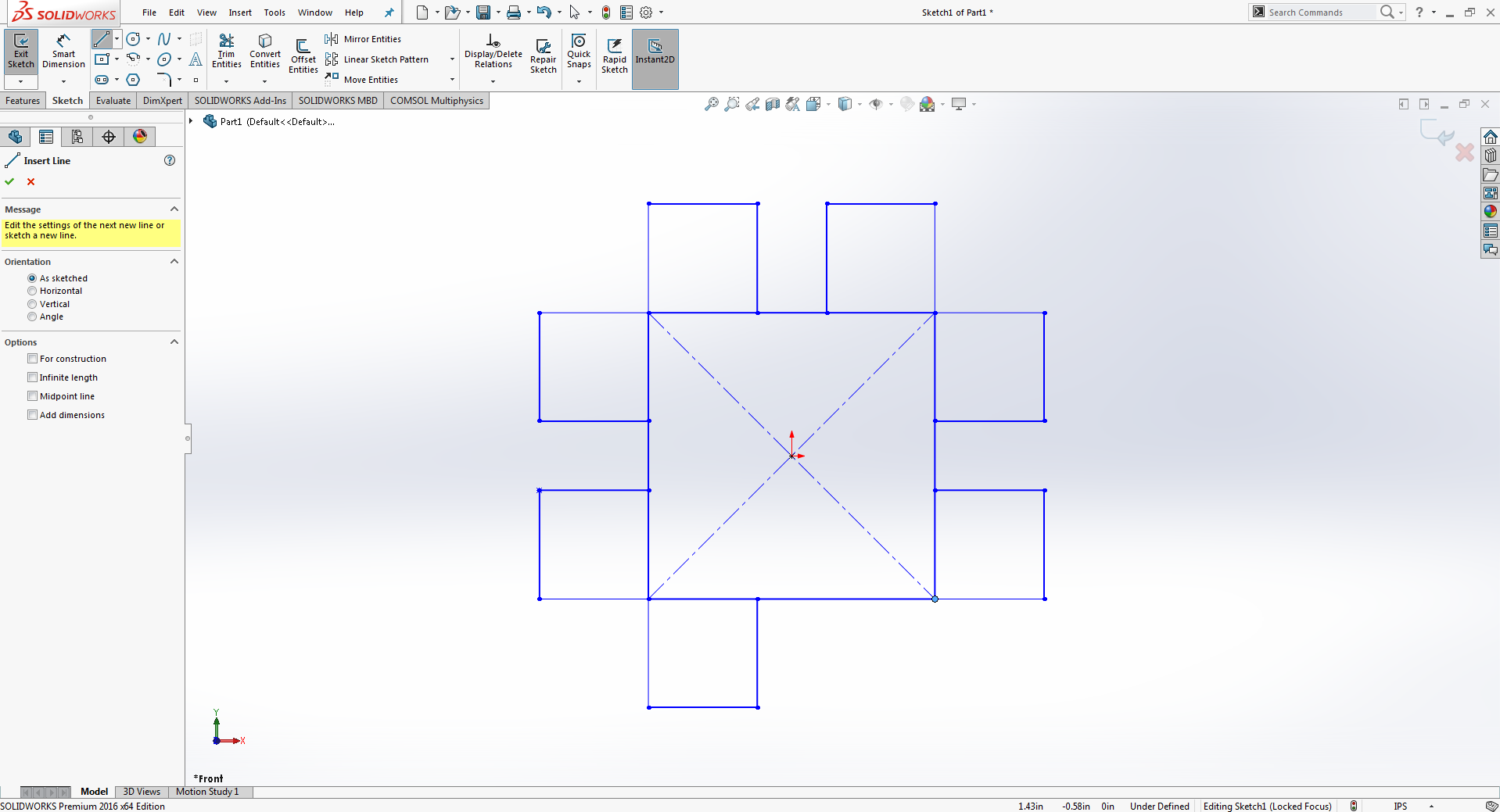
Go to file, click new and select part and press enter.
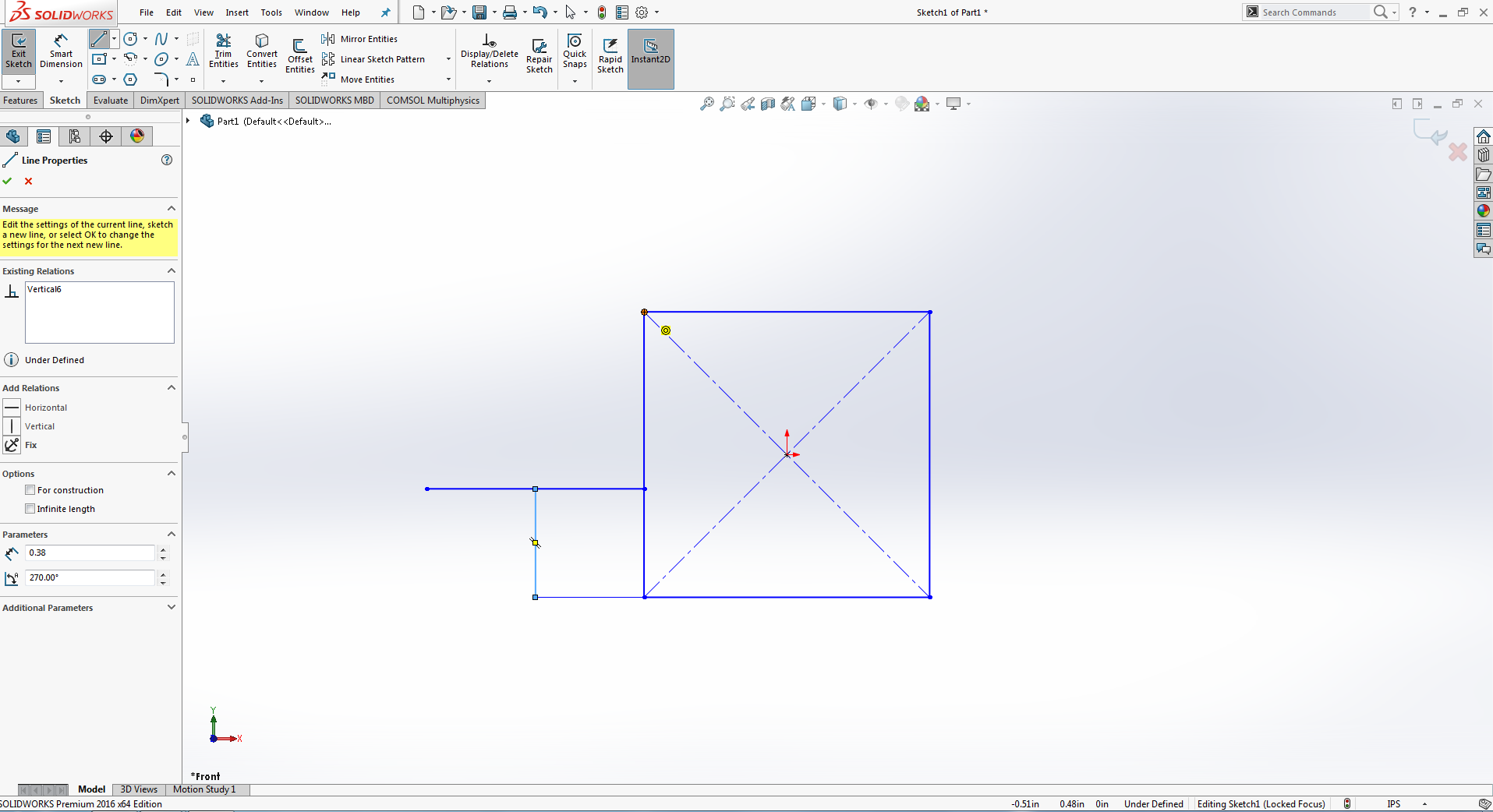
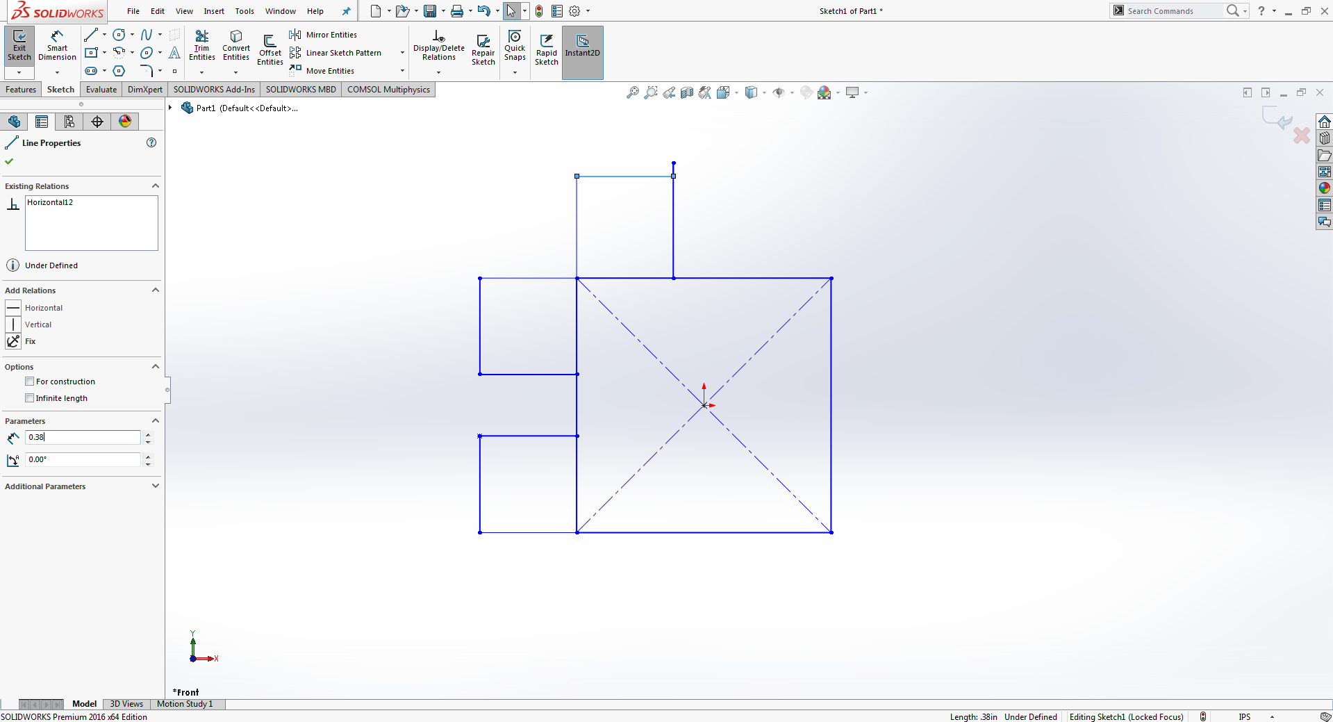
Draw reactangle on each sides.
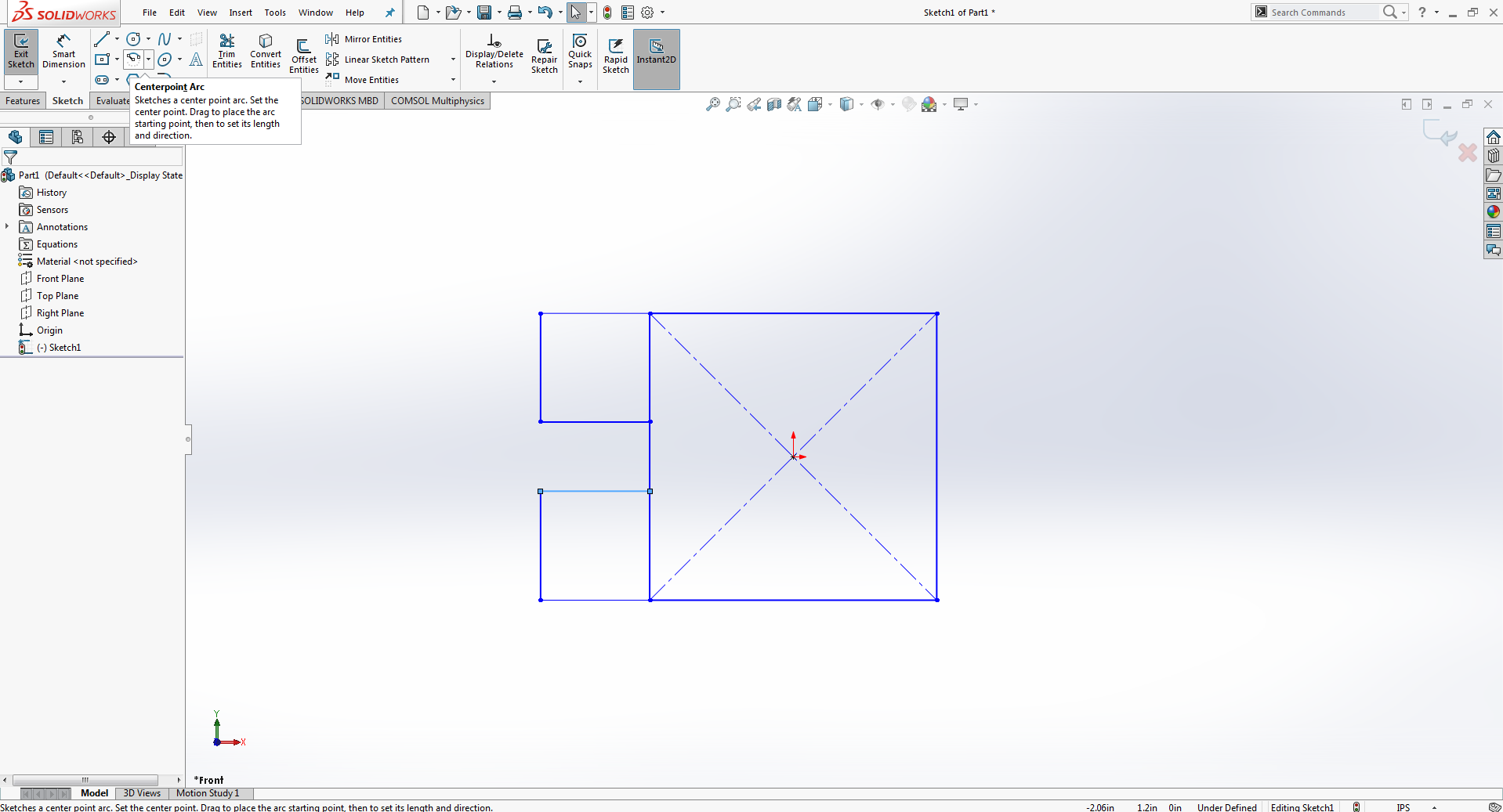
Draw small Square on square.
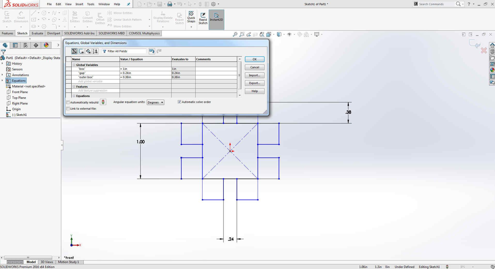
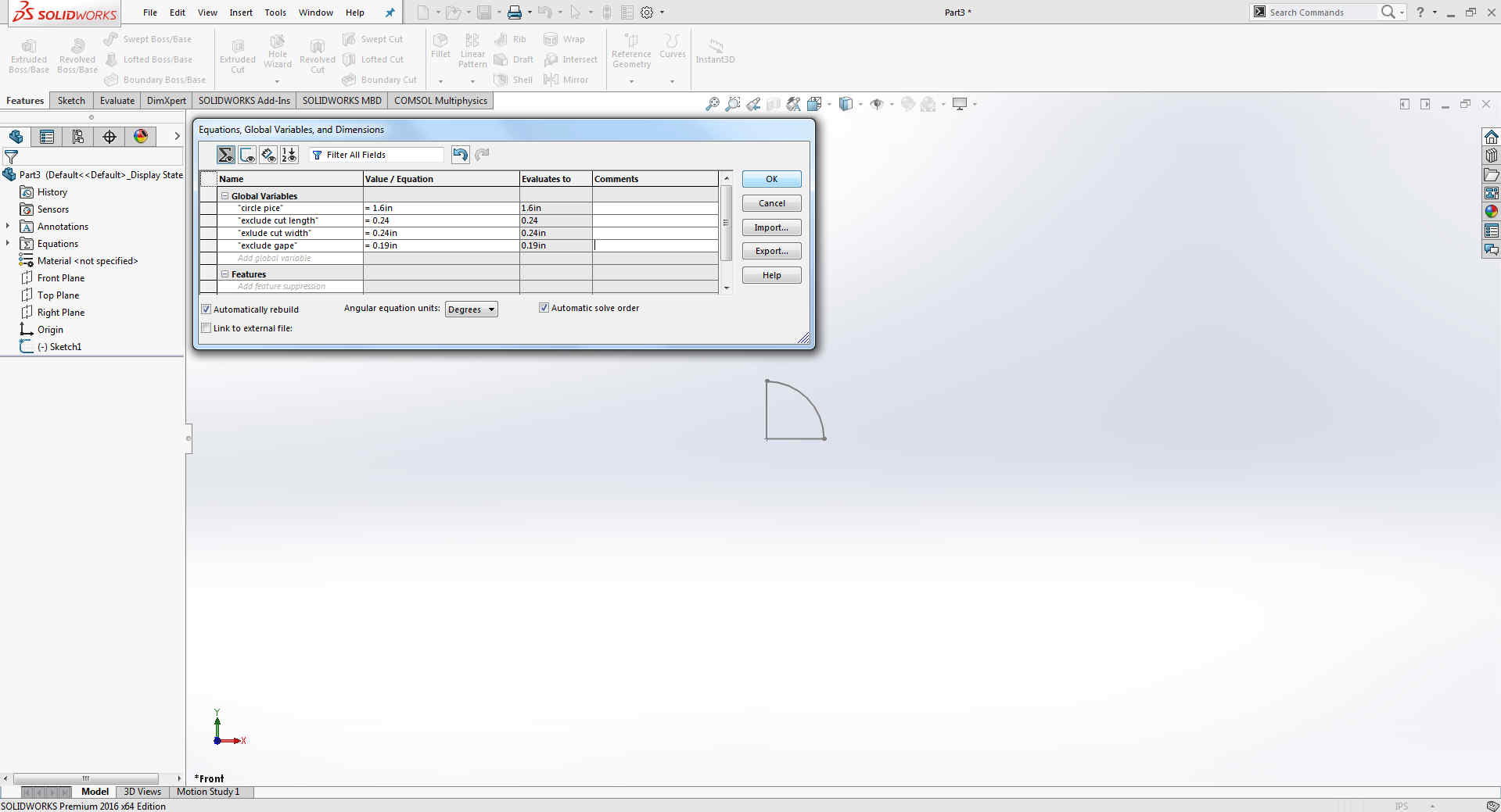
Go to Equations right click on manage equations give name, value and press ok.
Select smart dimention and press key = then select global variation ,After applying the equations it can be seen as.
I give the value of eclusion is 4mm because i am using cardboard so this is thickness of material which i am using.it can be change by changing value in equations.
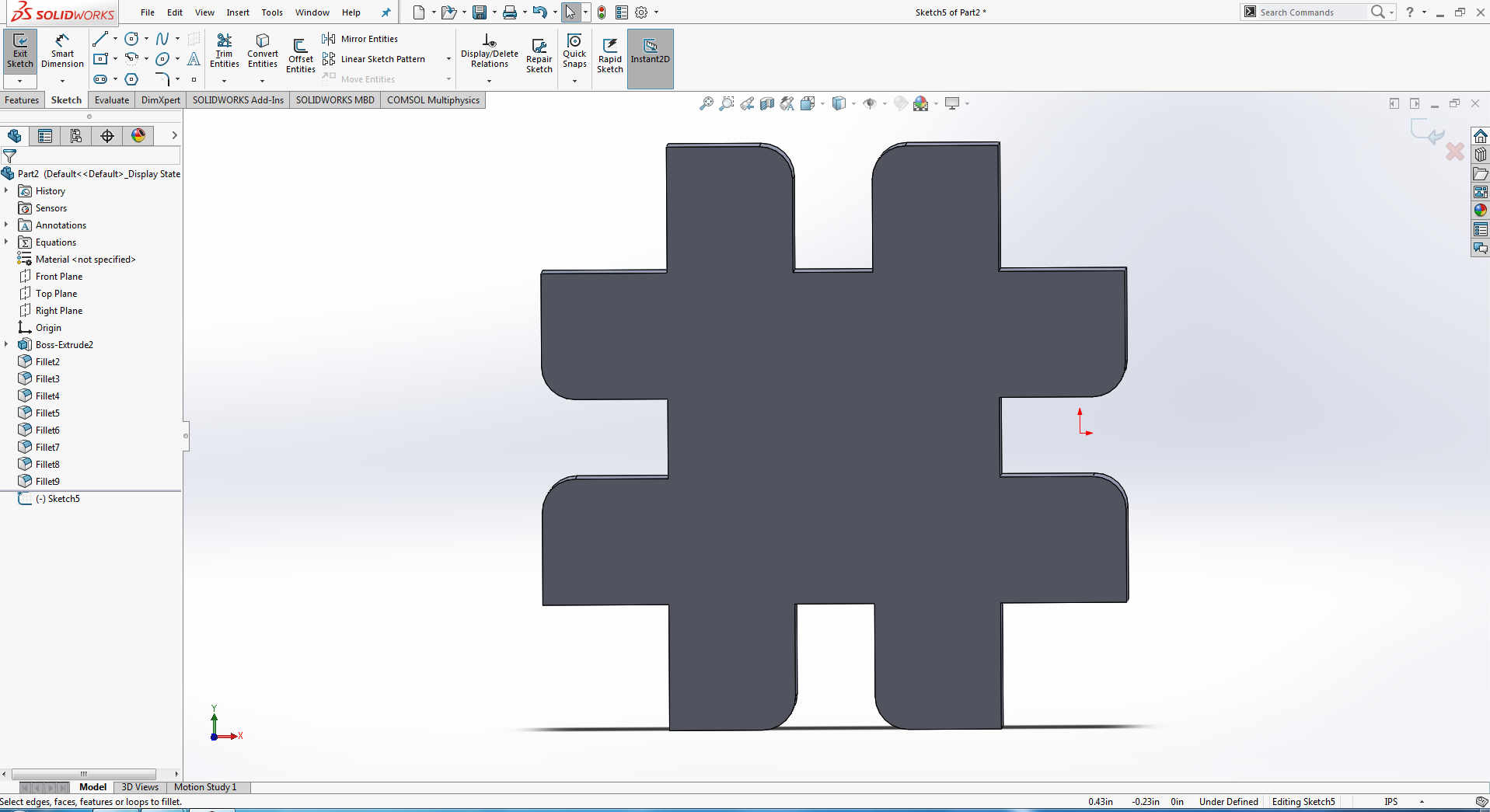
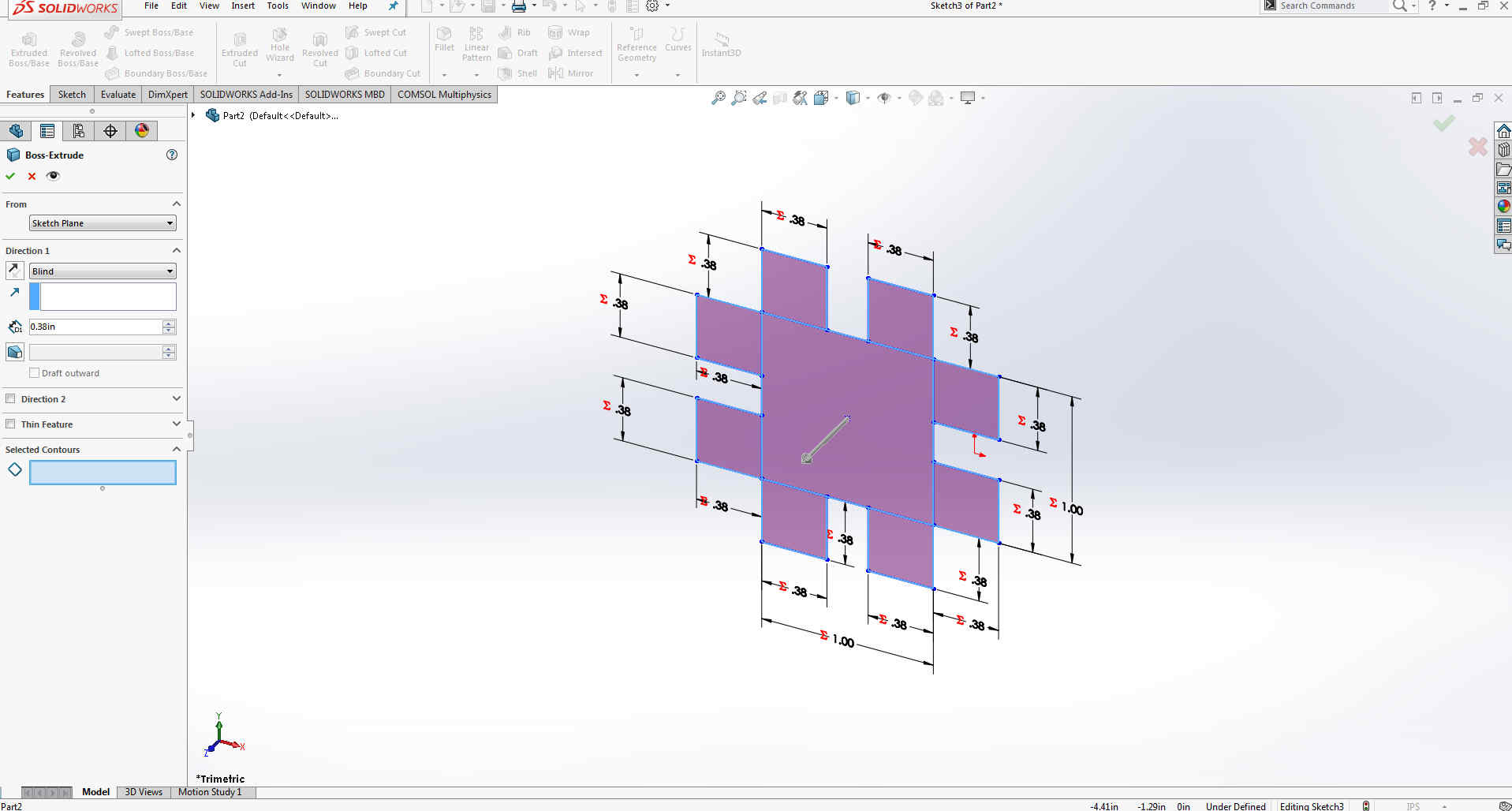
After exclusion it looks like this.
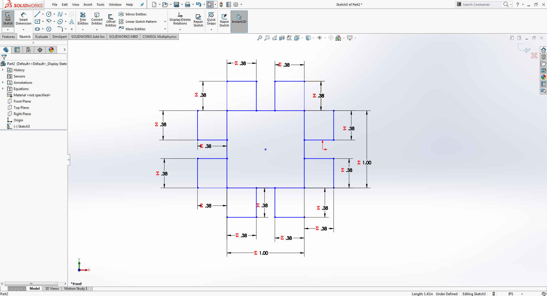
Now making other part and giving the equations same as before
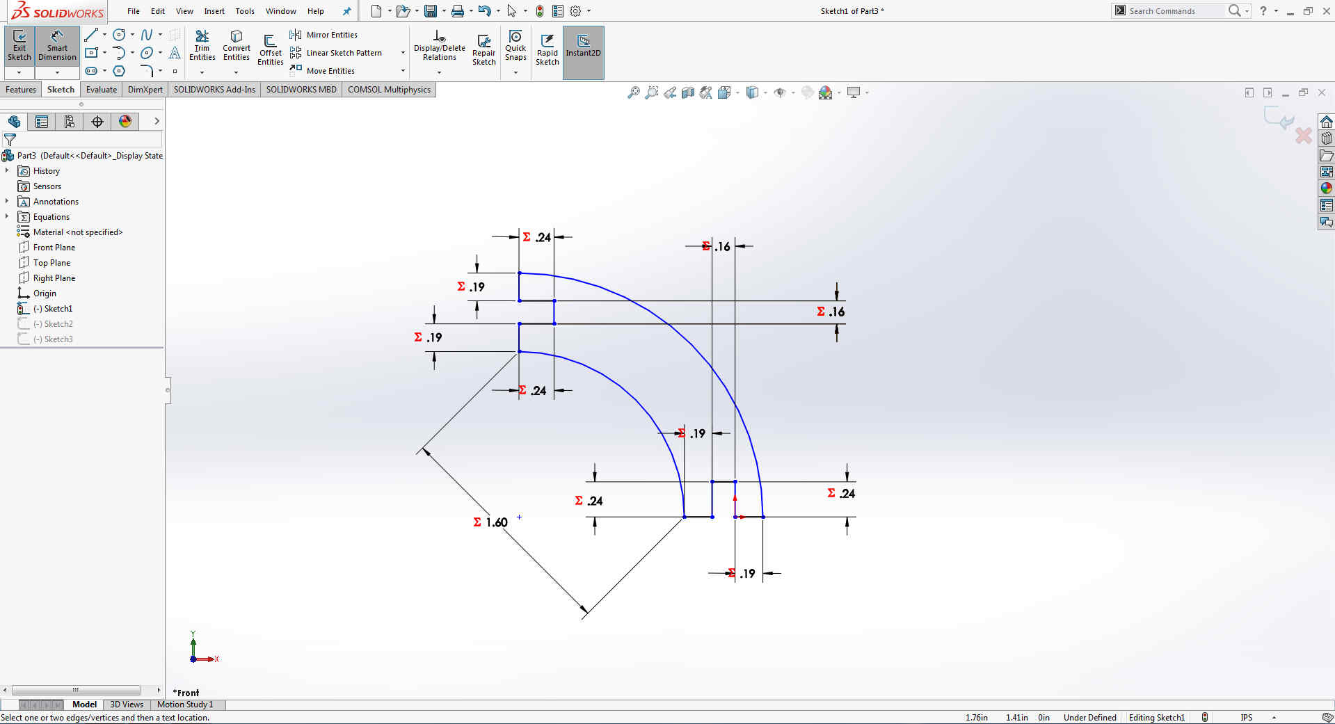
By selecting smart dimention and press key = go to global variation and apply equation on the drawings
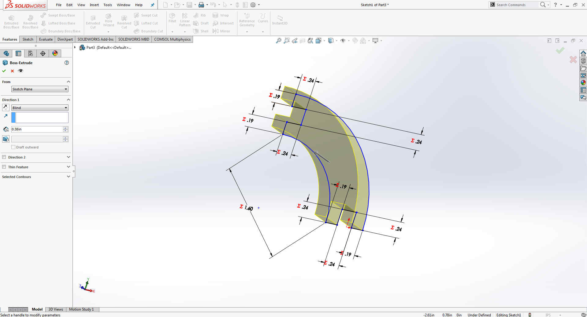
After Exlude imagae,This is angle which i need in my design
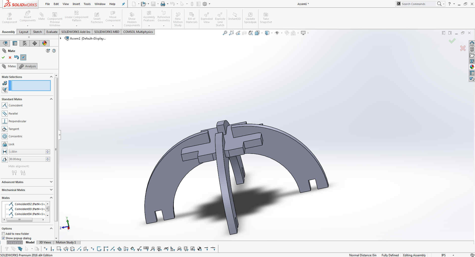
First I open all parts in Assembly, By using "Mate" tool several times I lock them together in a desired position.
Matting some more parts
Matting some more
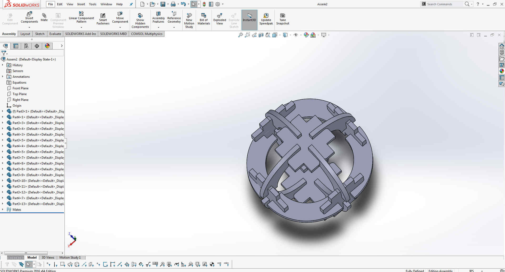
Its looks like a boll but i have to extend more.
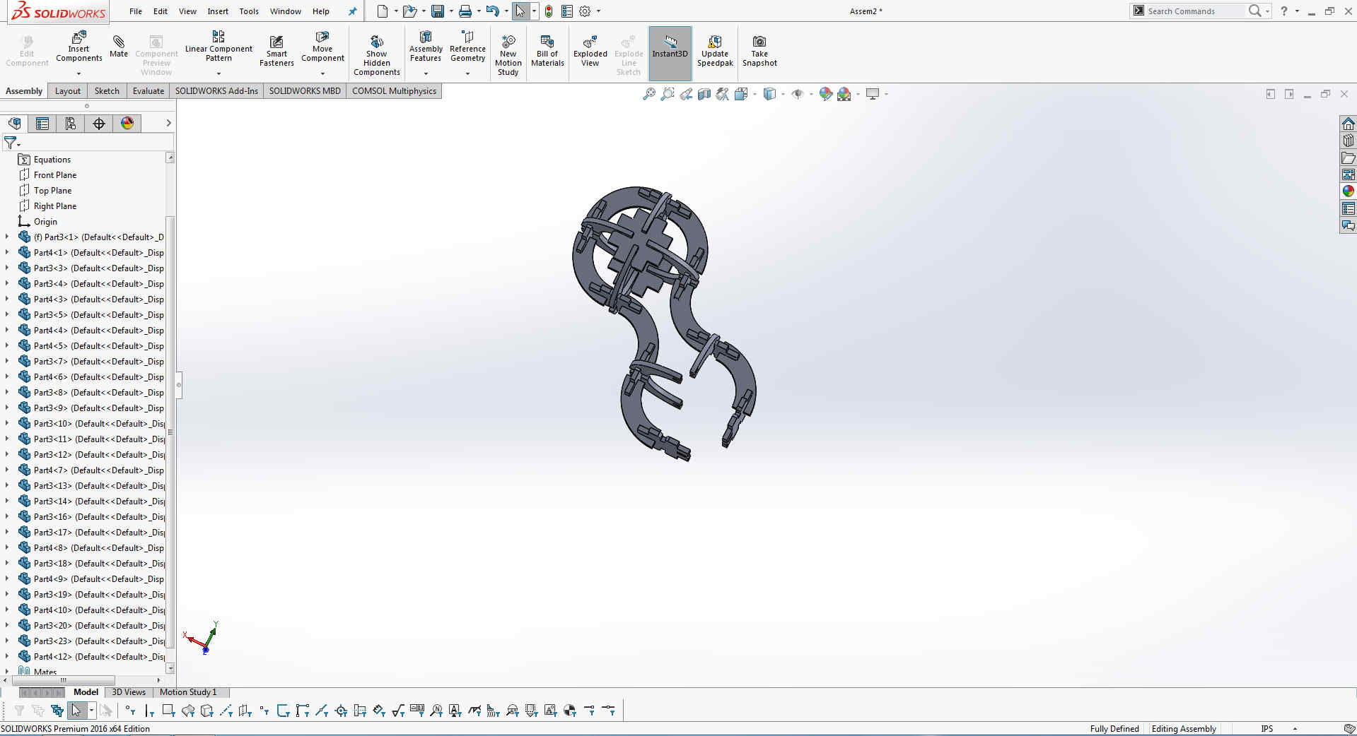
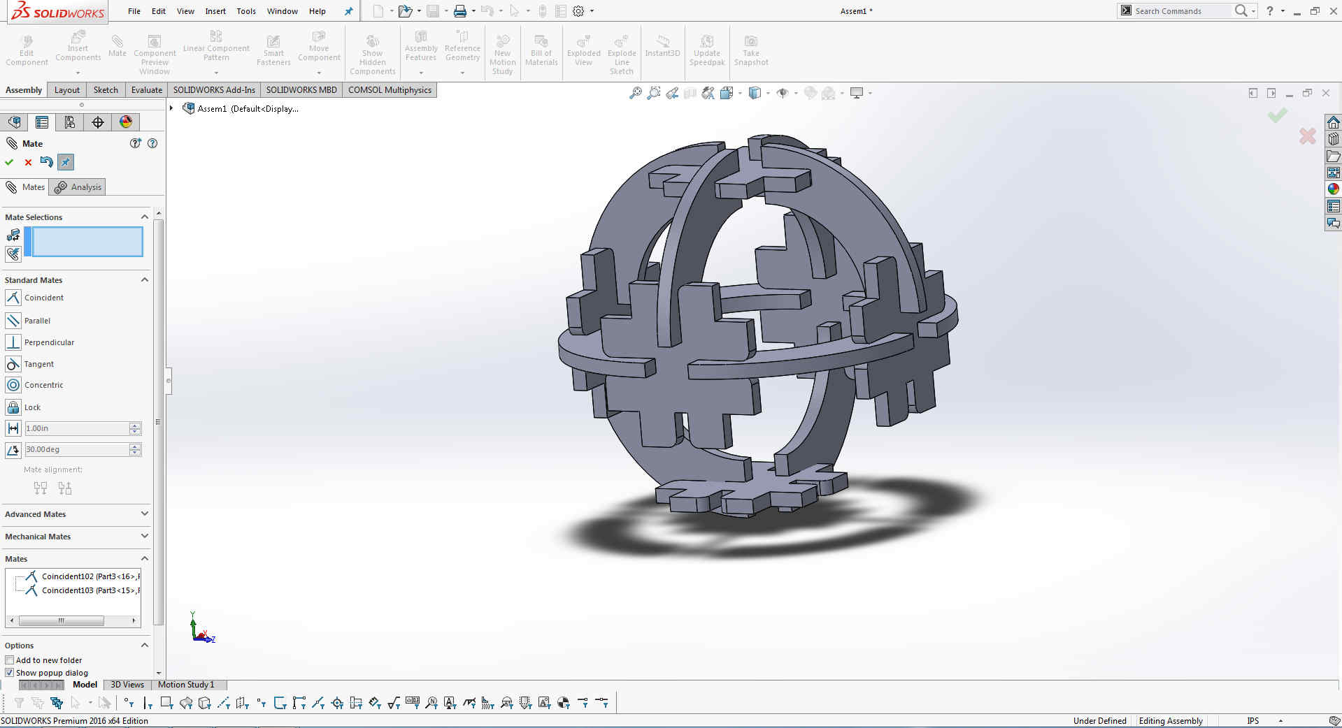
After matting the some more parts.
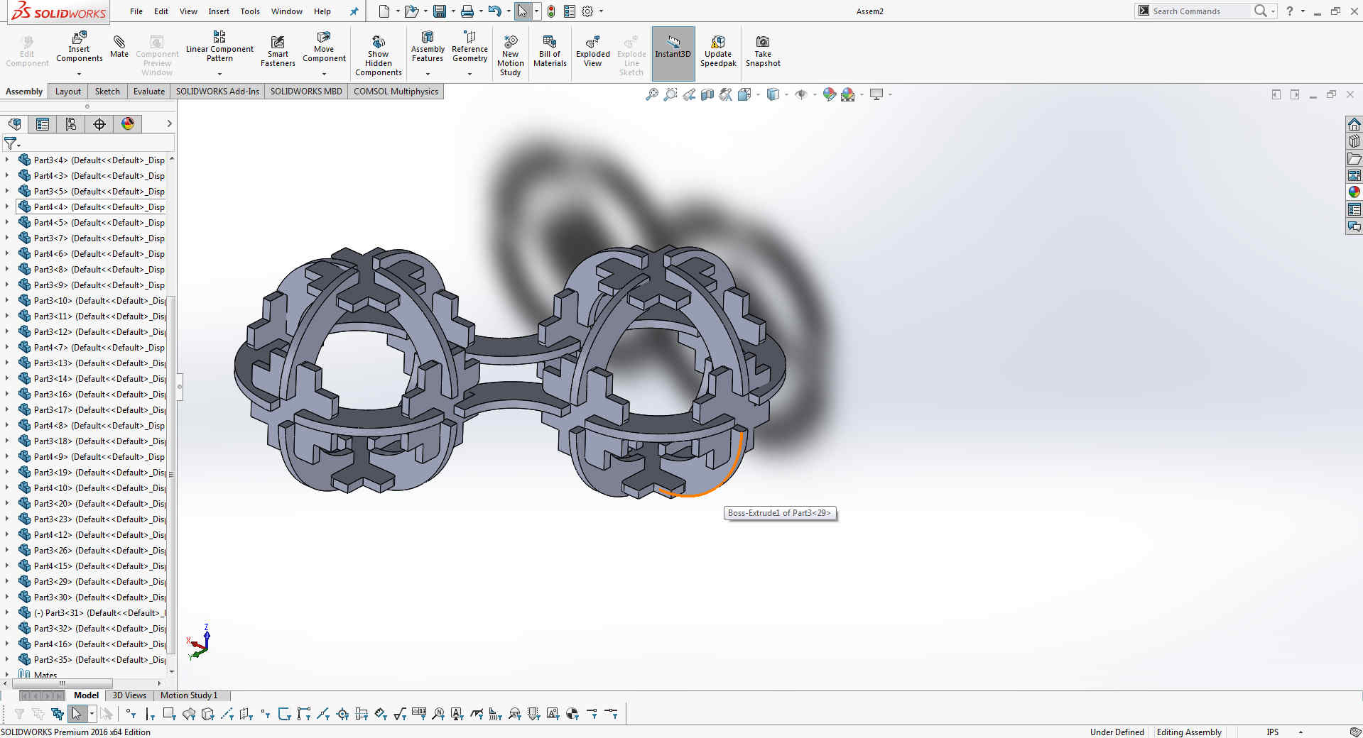
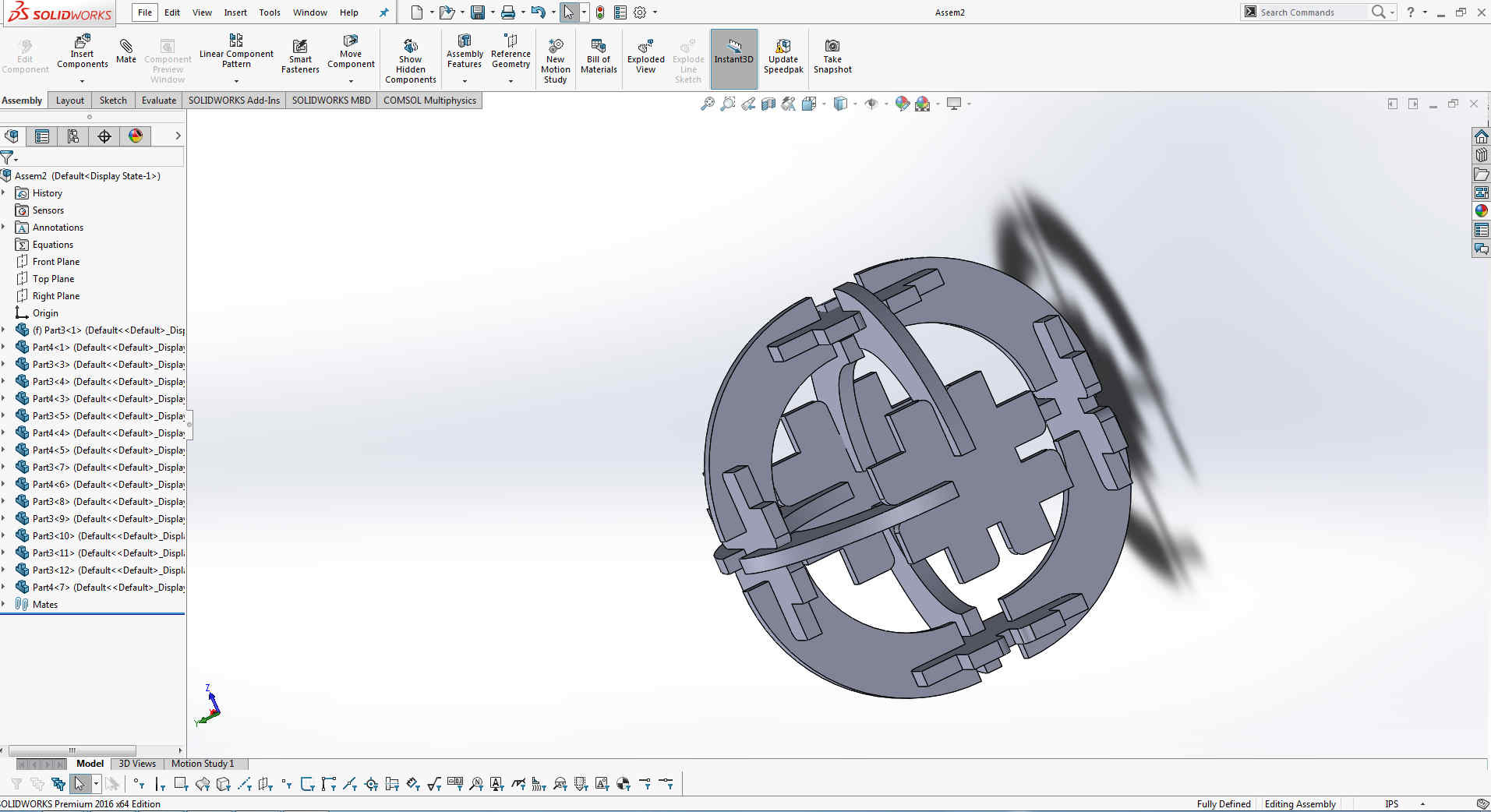
Now it is my complete design.
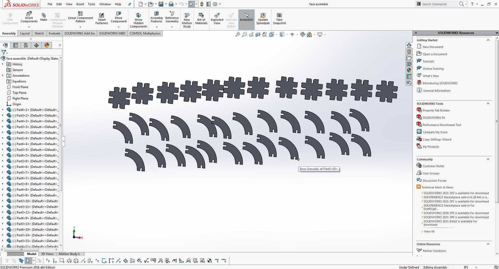
Make an other assemble file and put all in same face.
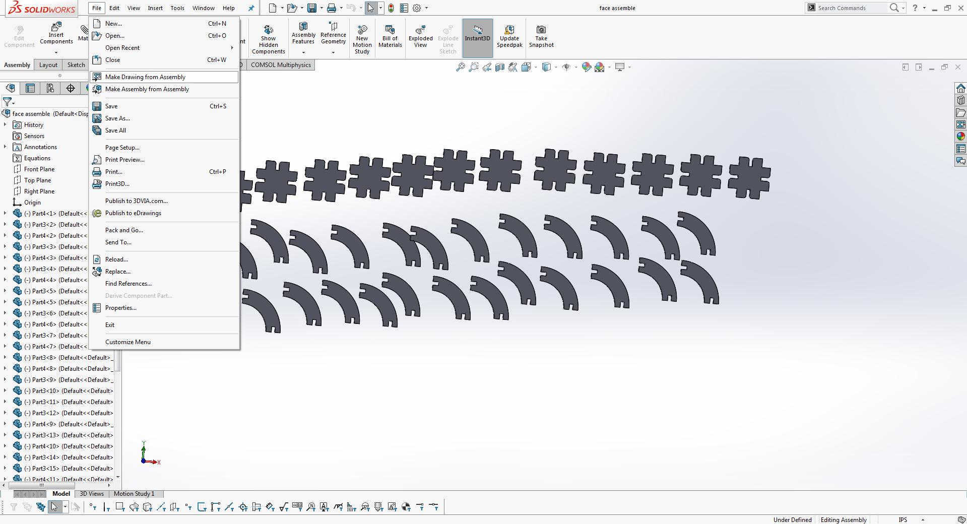
Go to file and make drawing from accembly
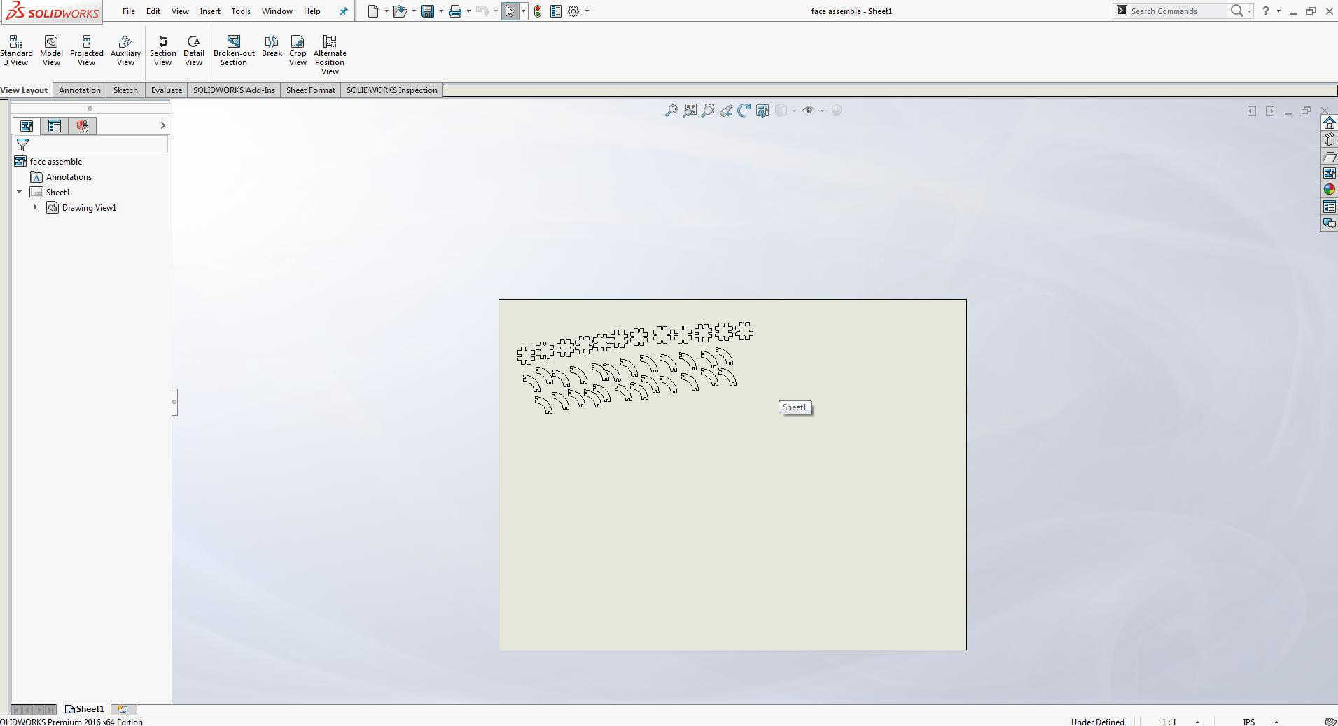
This window will open. and under defined 1x1
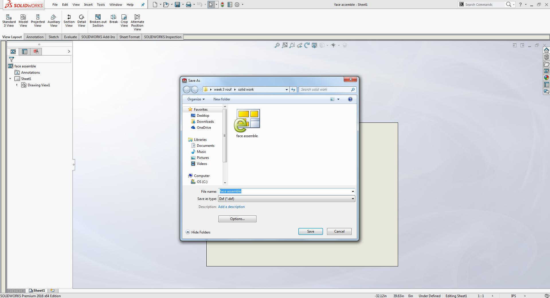
And save as Dxf file .
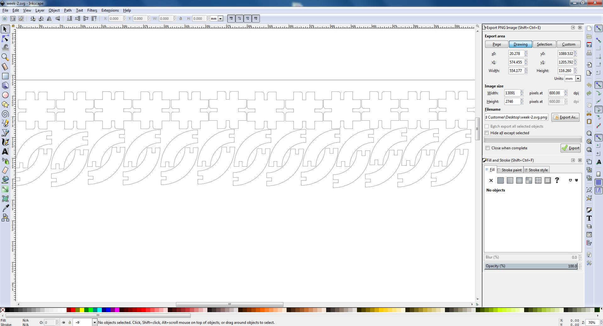
Open this file in inkscape allign all parts.
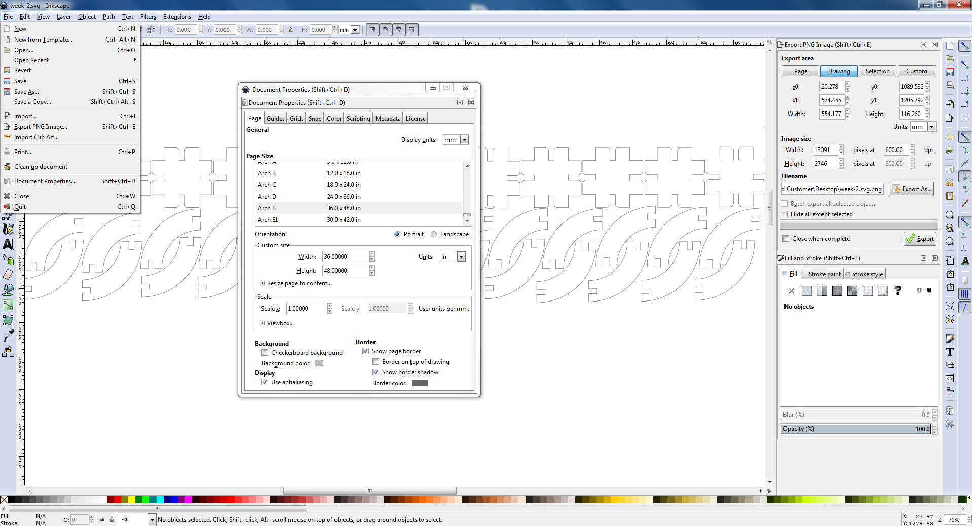
Go to file and click on document properties, select page as Arch E set DPI 600 and save as svg and Pdf format.
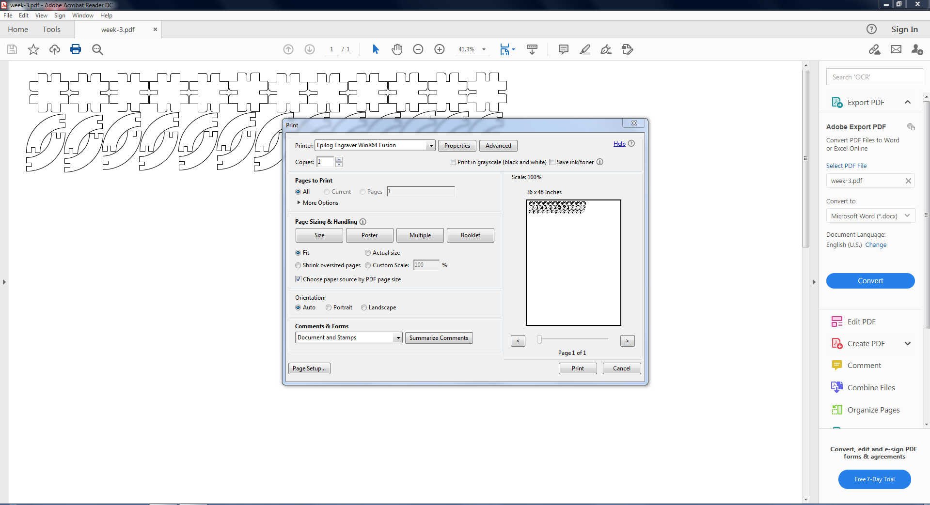
Press Ctrl+p or to print select printer and press ok
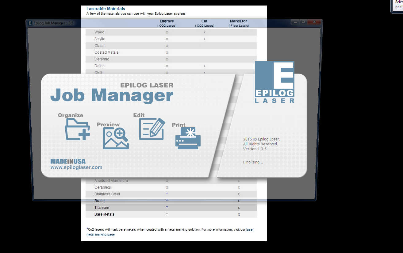
Now open Epilog laser software
Double click on your design.
Auto focus on and set thickness 4mm and vector grid ON and go to preview
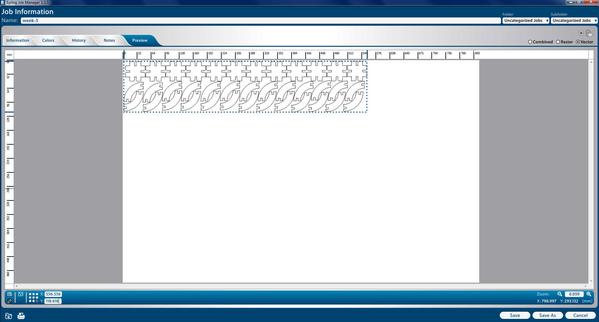
Allign your design with respect to sheet and click on save.
check again settings and click on save and give print
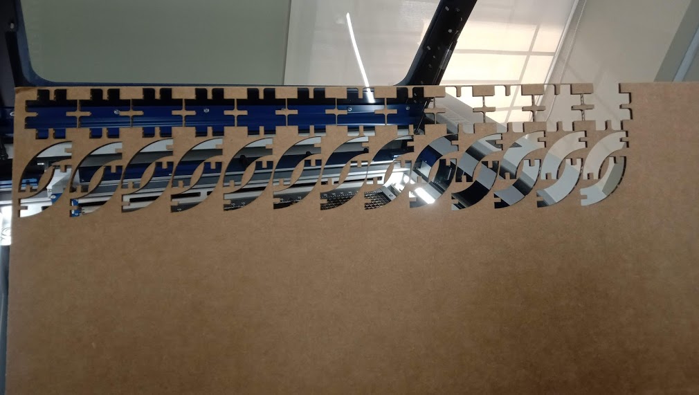
Removing the sheet
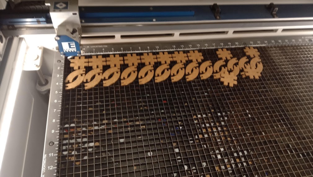
Lets collect the parts of my design from machine.
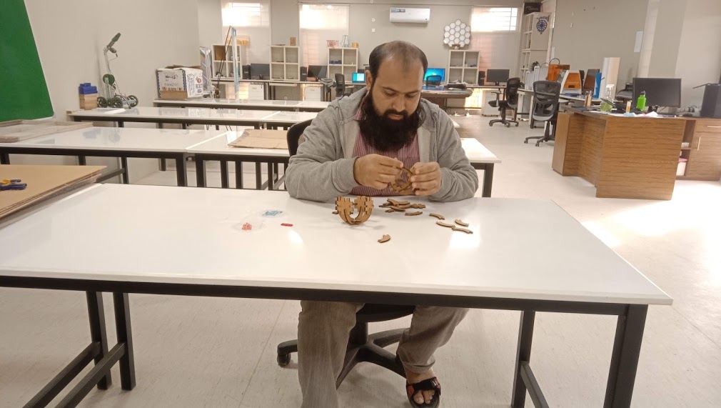
Joining the parts to each others
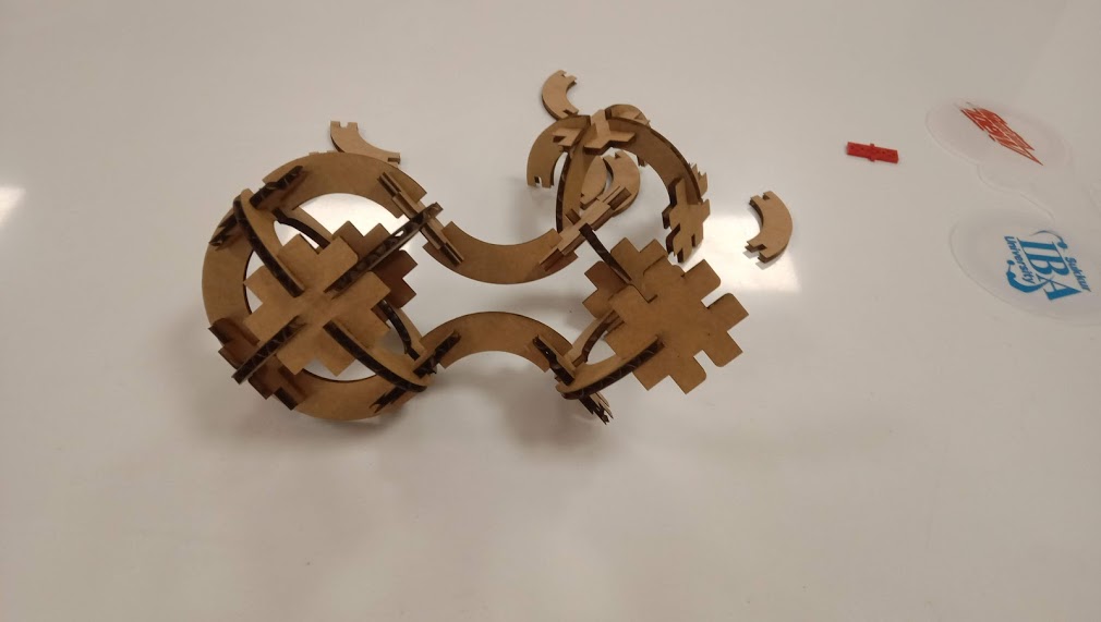
Few mats are remaining.
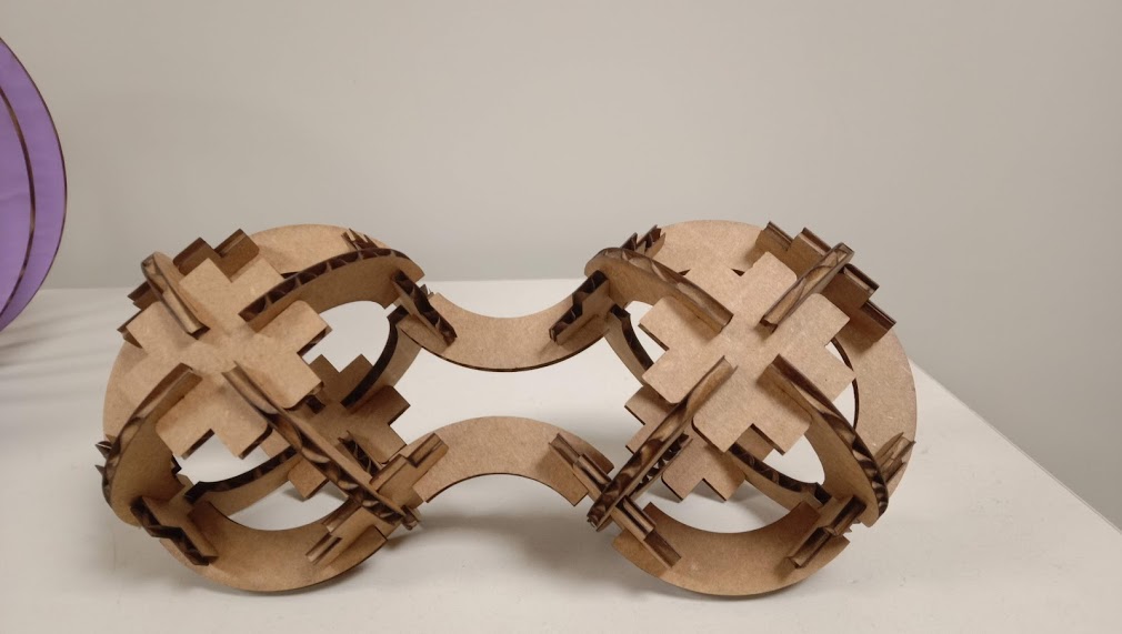
This is my final construction kit.
Vinyl Cutting
First, download the picture which I want to cut on a vinyl cutter. Open Inkscape software and import the image.>
Go to file, Click open
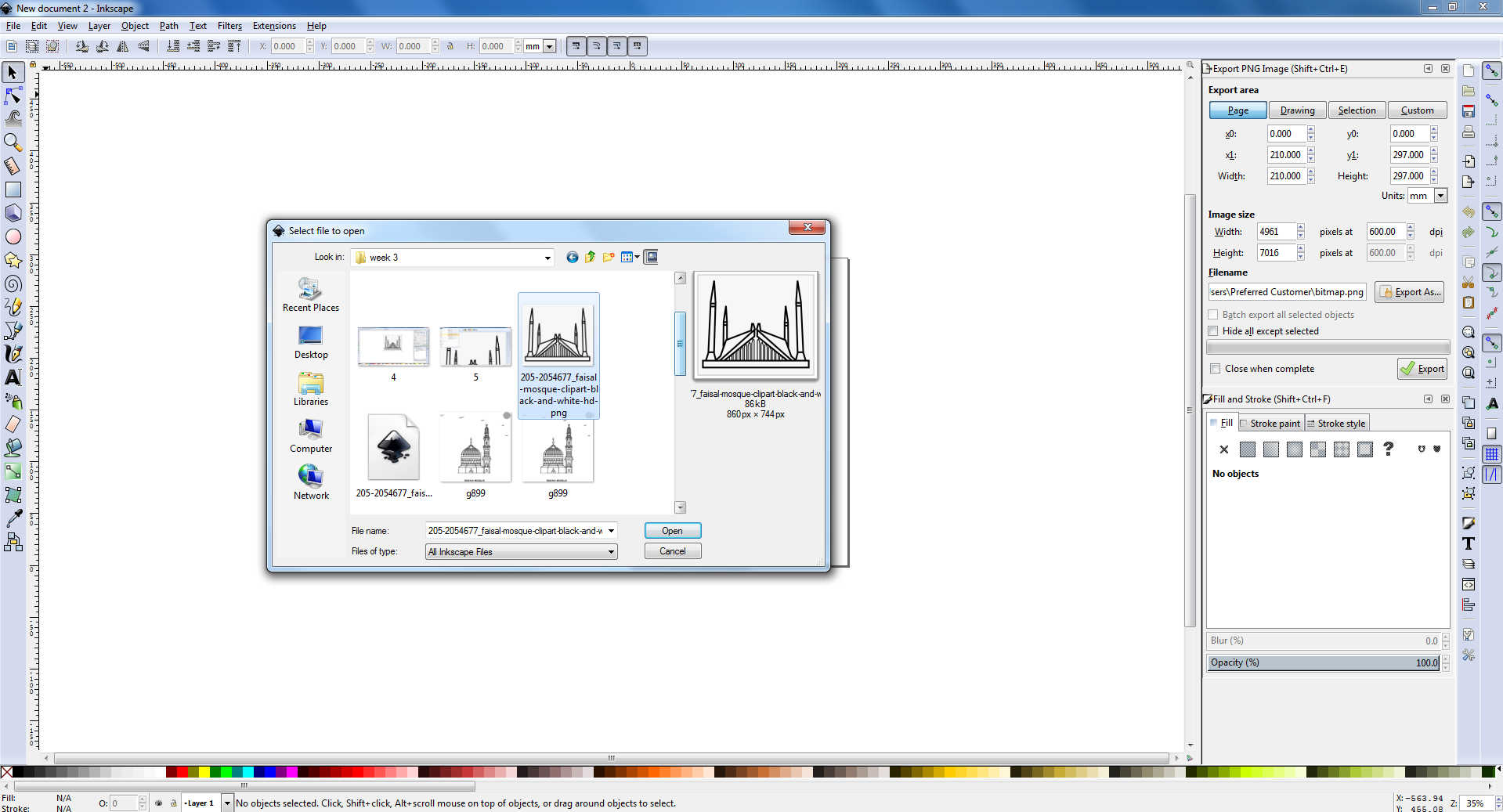
Select the image for vinyl.
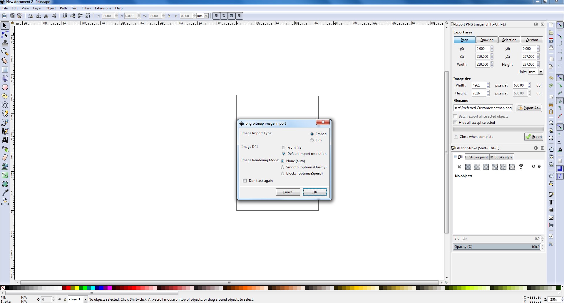
click ok.
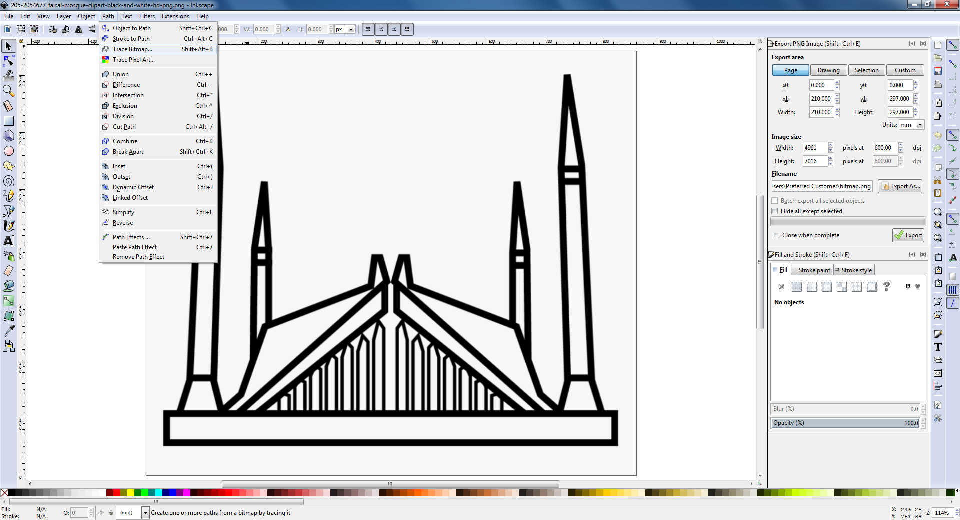
Go to path select trace bitmap or press shift+alt+B.
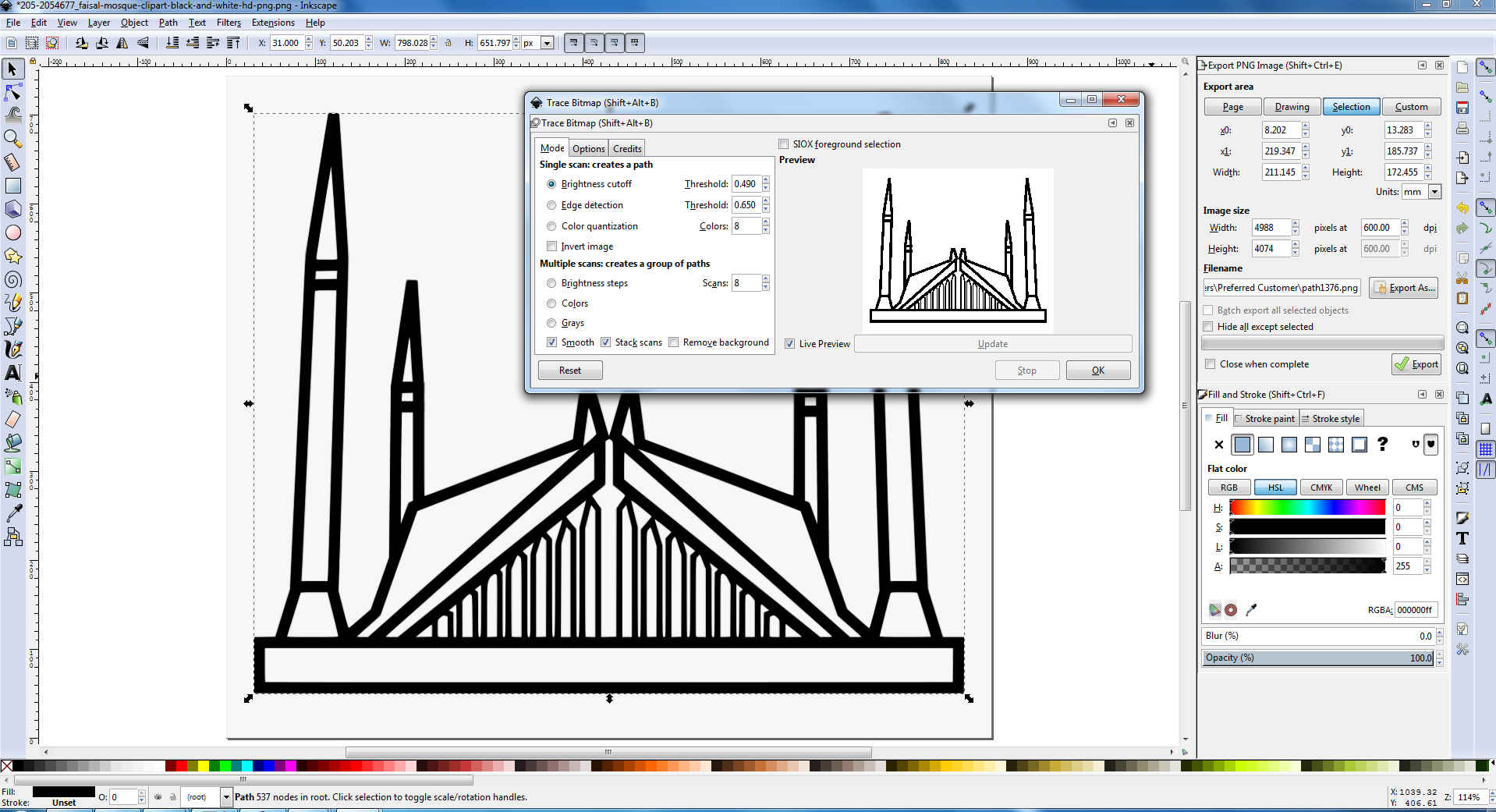
Now set the threshould value.
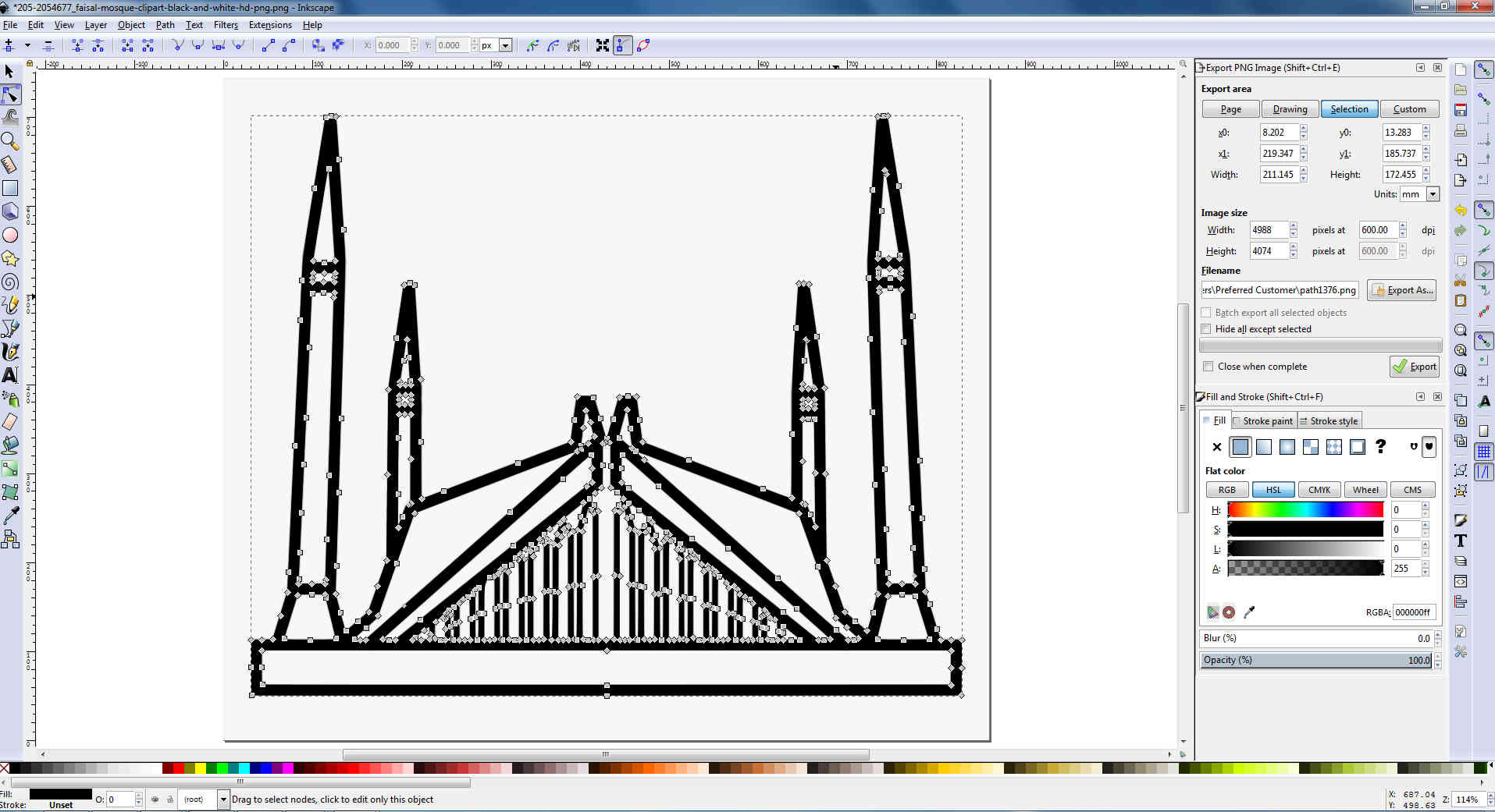
Now double click on image traces can be seen.
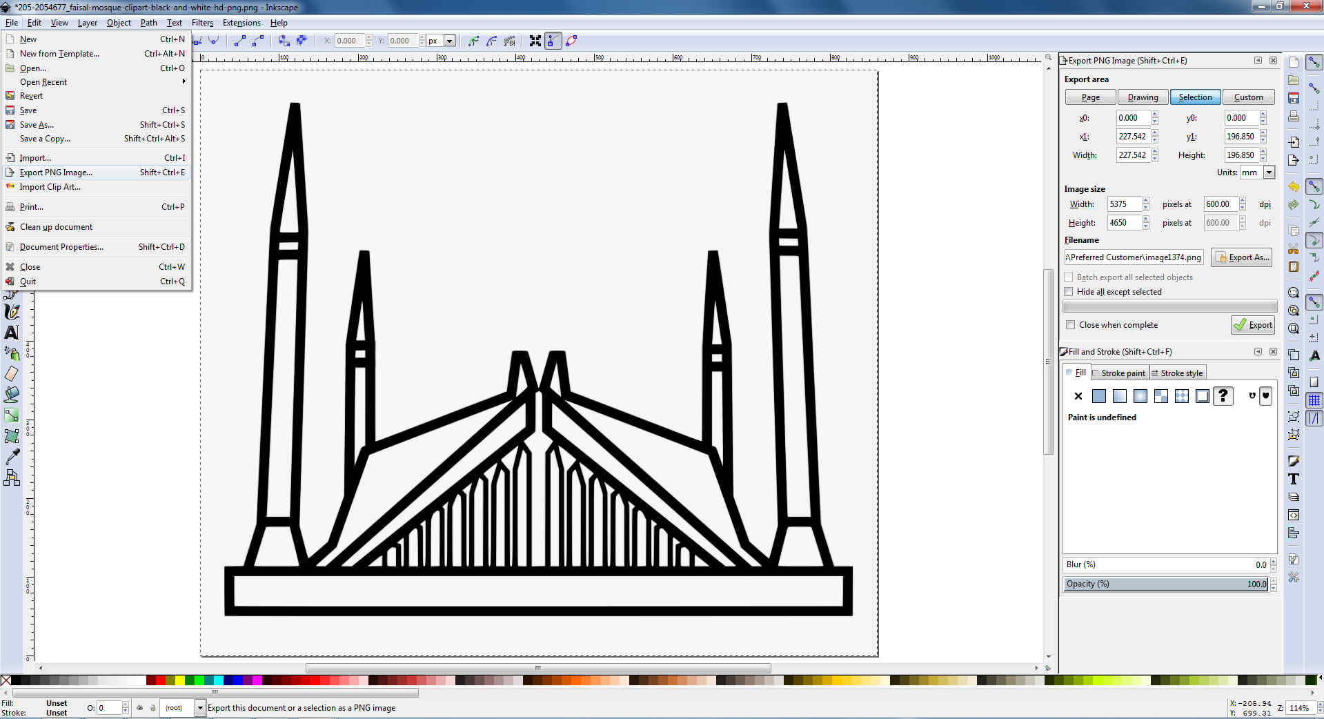
go to file then export image as a png format.
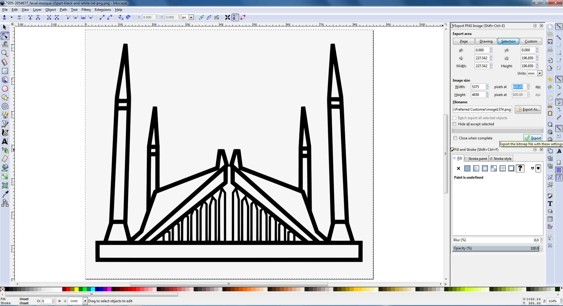
Now set the dots per inches (DPI), give location of export and press export.
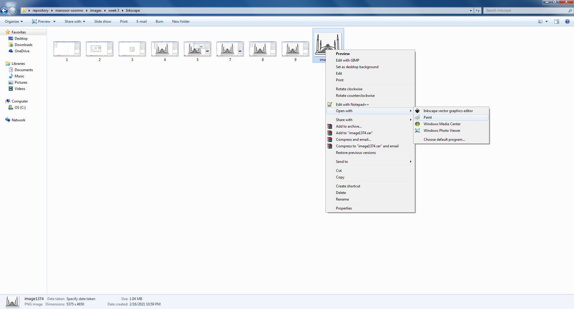
Now open image in the paint.
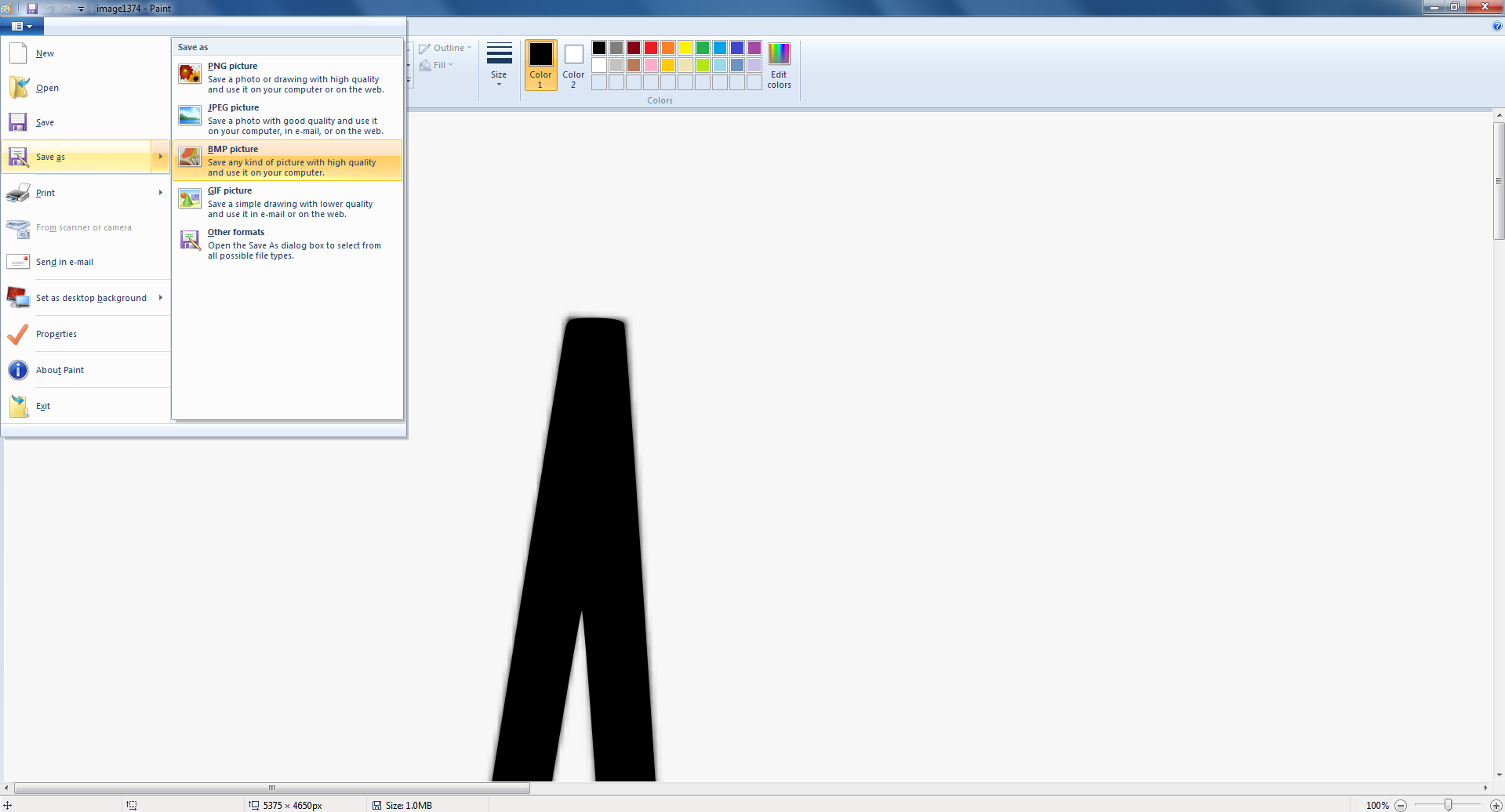
Go to file and save as bmp format.
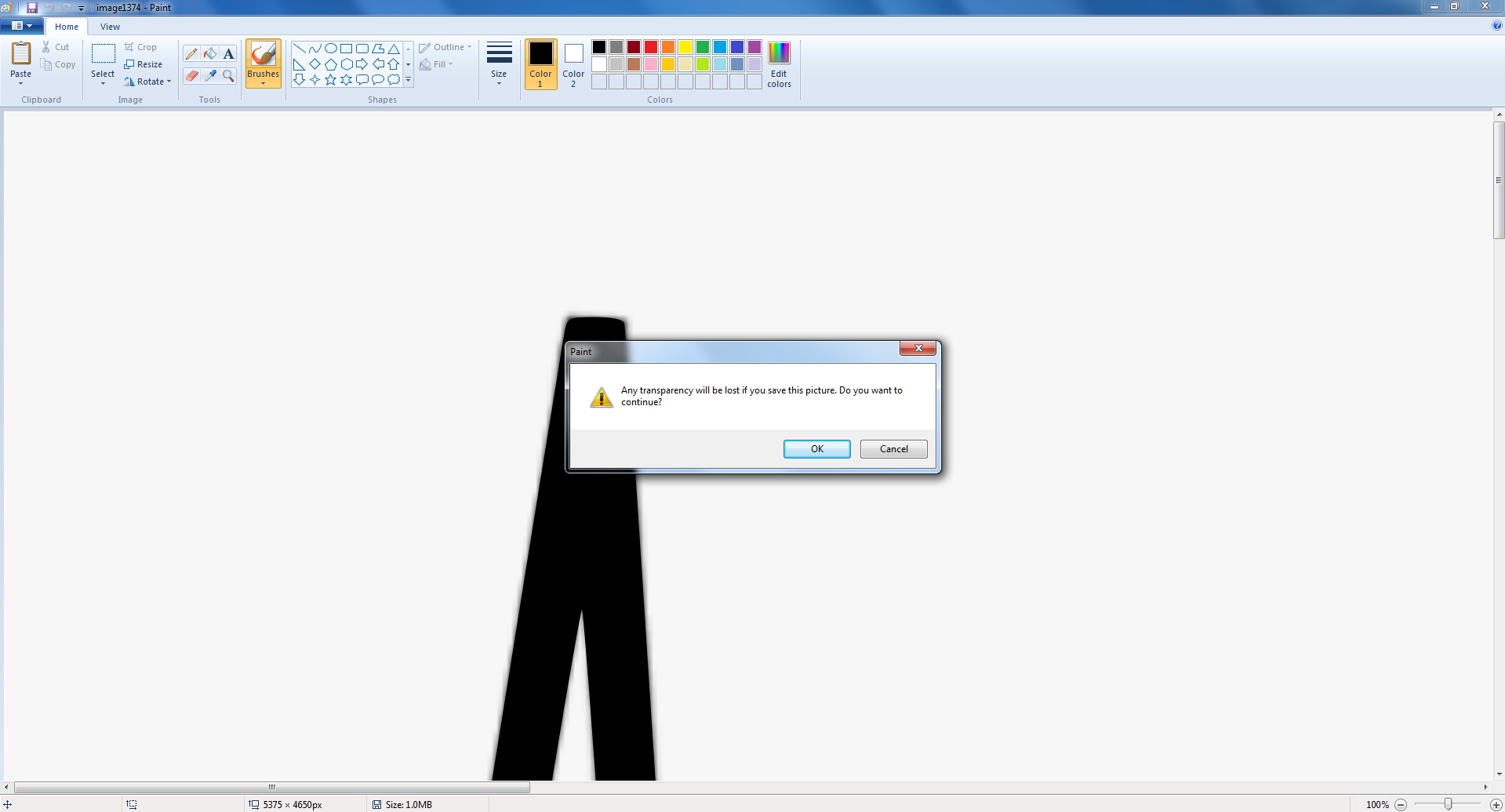
Press ok, now the image is converted in Bitmap format
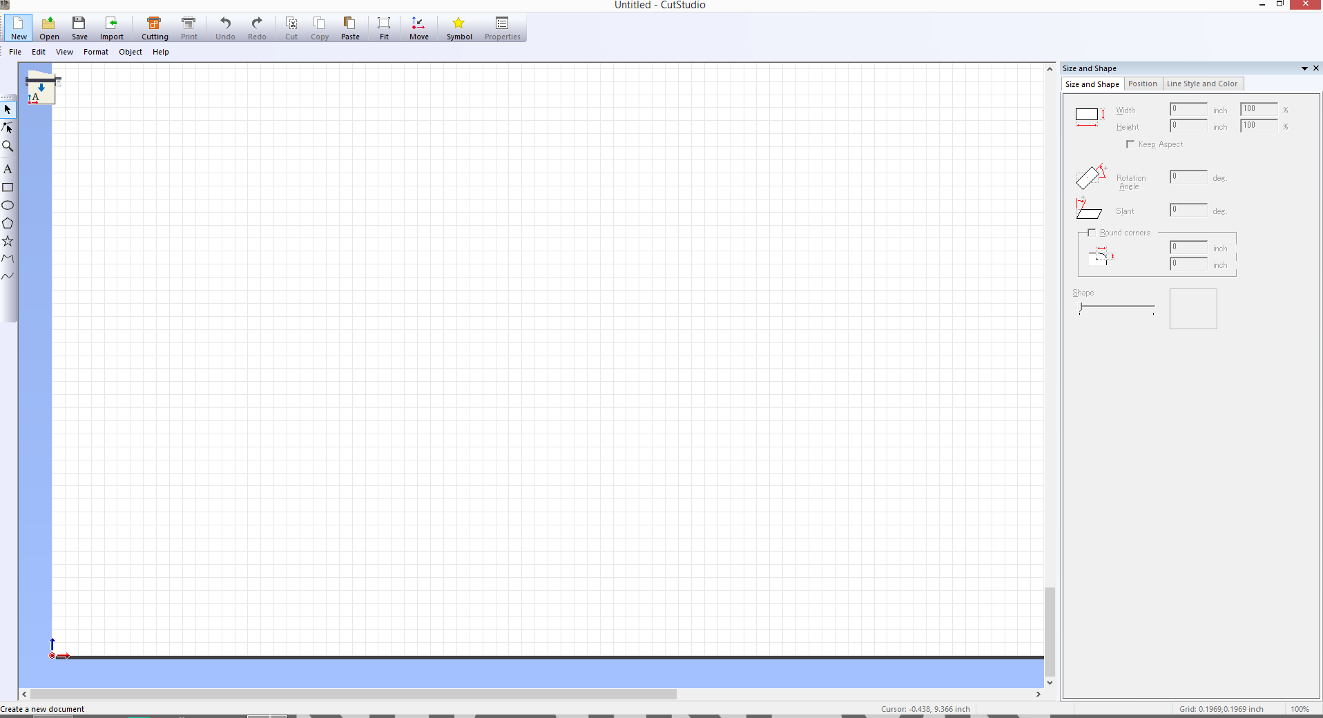
Now Open Roland Cutstudio and open Bitmap format image
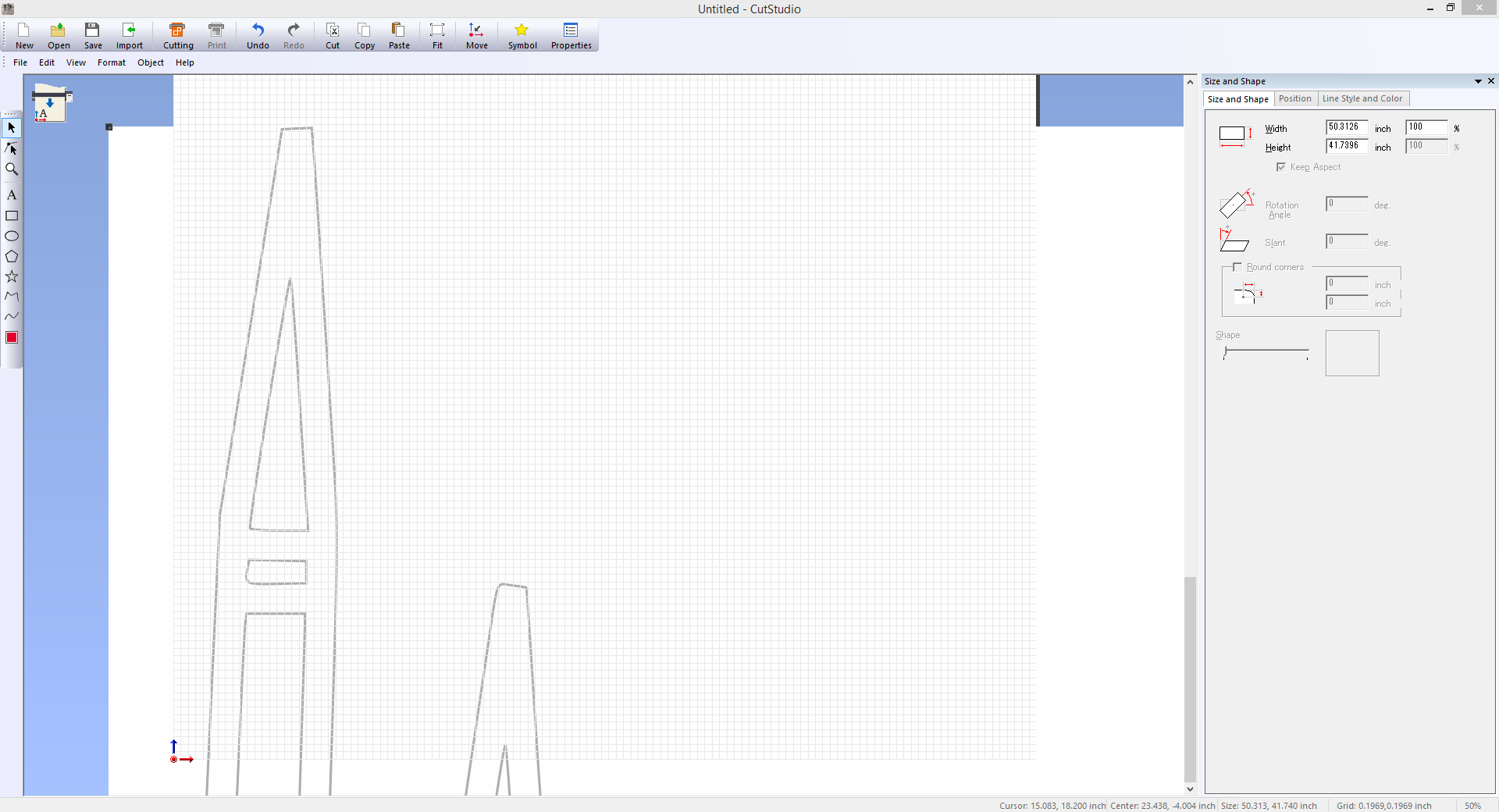
Drag the image
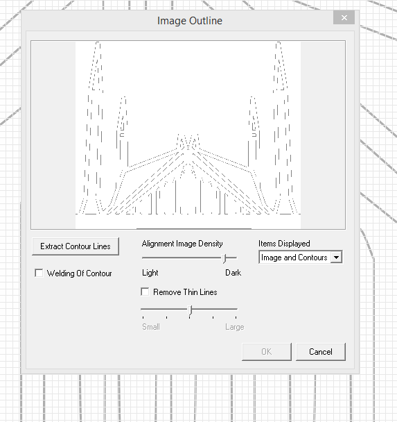
Right click on image go to the image outline and extract the contour lines
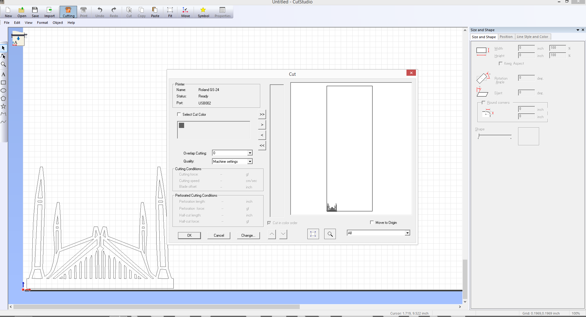
Now press key ctrl+p or click on cut then then click on change in order to get width and length from machine
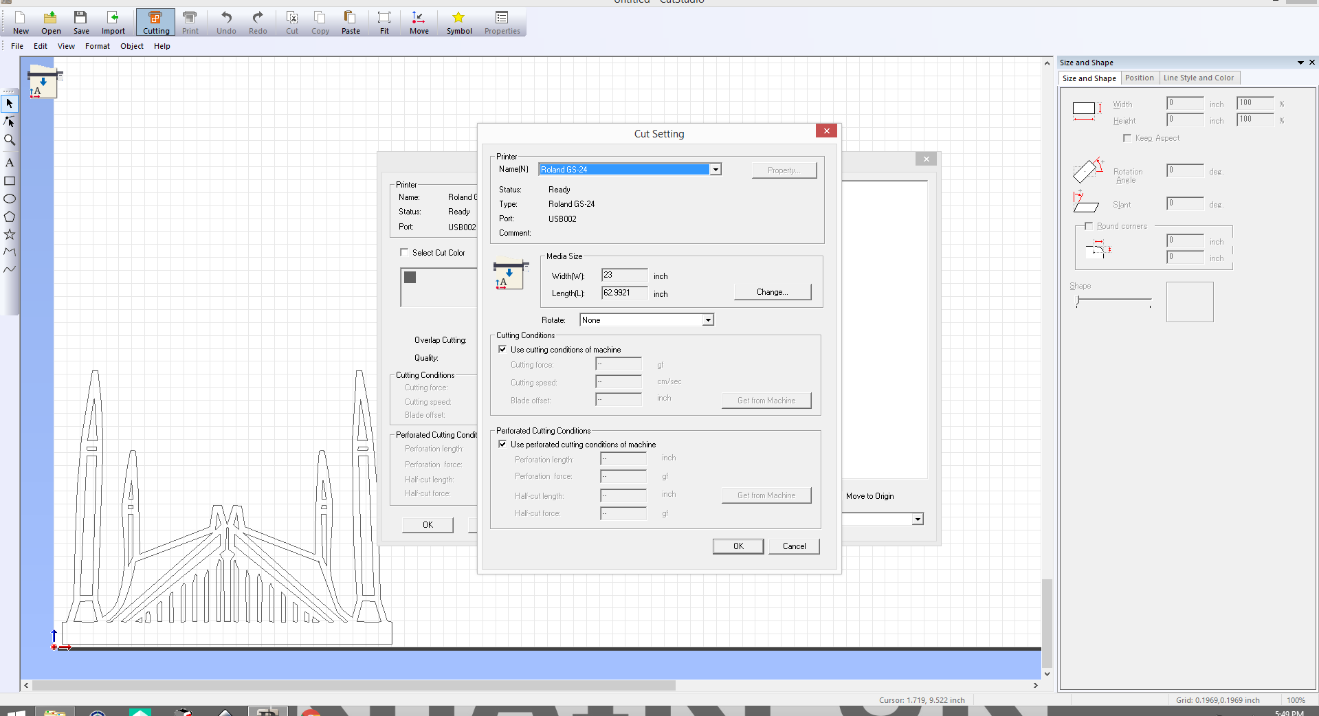
Click on change
Select get from machine and then click ok it will show you the size of your sheet in your software
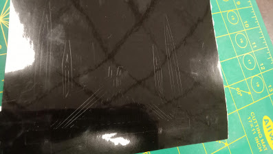
After cutting the sticker remove all the extra parts that are not needed in the final sticker.
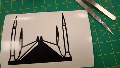
After removing some unwanted parts.
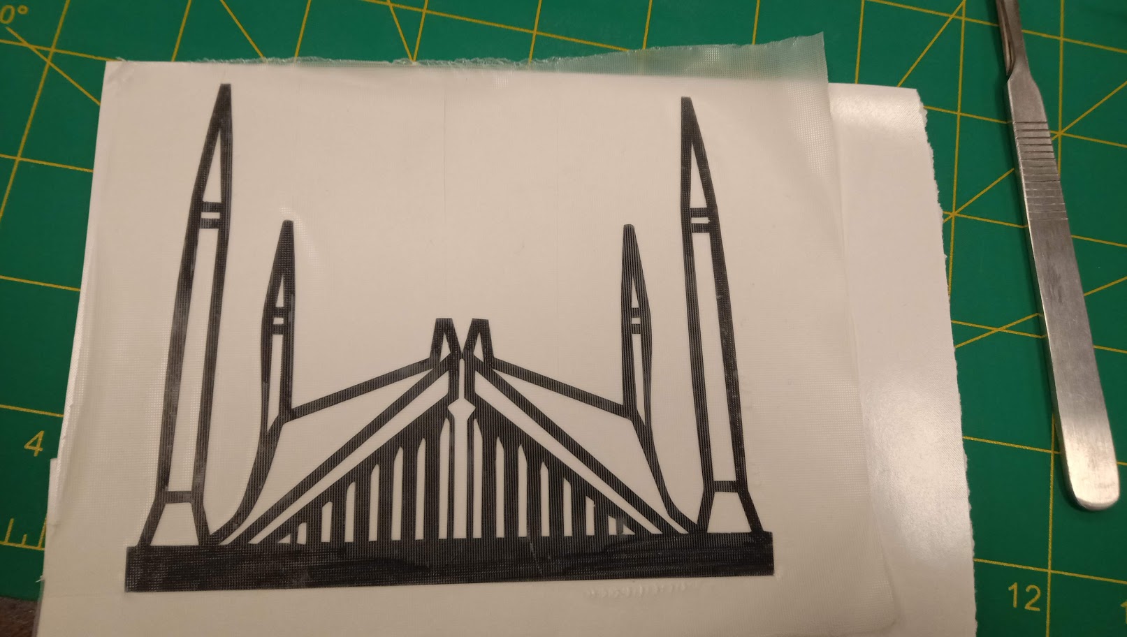
Apply face sheet to the sticker.
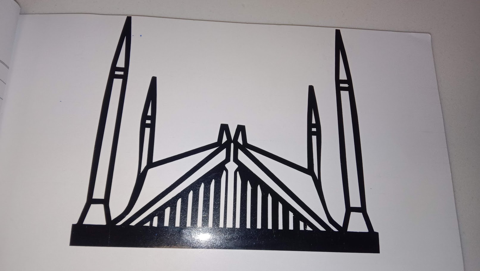
I pasted sticker on my Note book.

I Take some more vinyl cut and pasted to my Register
"Click here"to download all files of this week