Week - 12
Output Devices
Assignment
Group Assignment
- Measure the power consumption of an output device.
Power Consumption
We decided to find the power usage of motor drivers on various DC motors because one of our projects is about motor driver circuits. On that initiative, we take current measurements.

The input voltage is 12 volts.

The current drawn by a simple DC motor is 89.2mA.
A simple DC motor consumes 1.06W watts of total power.
The current drawn by a DC gear motor is 165.4mA. The total power consumption of DC gear motor is 1.884W.
Individual Assignment
- Add an output device to a microcontroller board you've designed, and program it to do something.
An output device is any piece of computer hardware equipment which converts information into human-readable form.It can be text, graphics, tactile, audio, and video. For my final project I need ultrasonic sensor as input devices and LCD ,buzzer as output device.So I decided to work on my final project board.I am using ESP32 controller for my project.I started working on design.
LCD(Liquid Crystal Display)
A liquid-crystal display (LCD) is a flat-panel display or other electronically modulated optical device that uses the light-modulating properties of liquid crystals combined with polarizers.Liquid crystals do not emit light directly,instead using a backlight or reflector to produce images in color or monochrome. 16x2 LCD contain 16 pin,which include GND,VCC,data pins,enable,read/write pins.

This LCD's working voltage ranges from 4.7 to 5.3 volts. It has two rows, each of which can contain 16 characters. With no backlight, the current consumption is 1mA. A 588 pixel box can be used to create any character. Alphabets and numbers are displayed on alphanumeric LCDs.
LCM-SO16O2DTR/M Pin Out:
In our FAB inventory we have LCM-S01602DTR/M 16 X 2 LCD display.The 16 X 2 LCM-S01602DTR/M pin out is shown below.

This is the back side of lcd where two inital pins 15,16 are No Connections
- Pin1 VSS : - This is a GND pin of display, used to connect the GND terminal of the microcontroller unit.
- Pin2 VDD: - This is the voltage supply pin of the display, used to connect the supply pin of the power source.
- Pin3 V0: - This pin regulates the difference of the display, used to connect a changeable POT that can supply 0 to 5V.
- Pin4 RS: - This pin toggles among command or data register, used to connect a microcontroller unit pin and obtains either 0 or 1(0 = data mode, and 1 = command mode).
- Pin5 R/W : - This pin toggles the display among the read or writes operation, and it is connected to a microcontroller unit pin to get either 0 or 1 (0 = Write Operation, and 1 = Read Operation).
- Pin6 E : - This pin should be held high to execute Read/Write process, and it is connected to the microcontroller unit & constantly held high.
- Pin7-14 DB0-DB7: - These pins are used to send data to the display. These pins are connected in two-wire modes like 4-wire mode and 8-wire mode. In 4-wire mode, only four pins are connected to the microcontroller unit like 0 to 3, whereas in 8-wire mode, 8-pins are connected to microcontroller unit like 0 to 7.
- Pin15-Pin16 NC: - Pin 15 and 16 are not connected pins.Don't connect anything to that pin.Just connect pin 1 to 14 to backpack.
Install the LCD display library to Arduino:
After connecting the microcontroller to the 16x2 LCD module, the next move is to download an arduino liquid crystal library. Take the following steps:
- Step 1.download Liquid crystal library
- Step 2. Go to Arduino IDE.
- Step 3. Go to sketch -> Include Library -> Add.zip file

Programming:
you can find example for the library, if you see through the following picture.

This is the Arduino Program for output display any thing.
To include the library
#include
defining the pins which need to connect to the ardiuno board
Const int rs= 5, en =4, db4 =0, db5 = 1, db6 = 2, db7 = 3;
liquidcrystal lcd(rs, en, db4, db5, db6, db7)
where RS is reset pin en is enable pin and db are data pins which can be changed
To define the lcd number of colums and rows
because i am using 16X2 lcd so i defined as
lcd.begin(16, 2);
To set what massage show to screen
lcd.print("mansoor ahmed");
To set cursor we define colum and line
lcd.setcursor(0,1)
As seen below in image.

This is final output of my board which is showing output on display

This circuit was designed and built during week 10. link
Buzzer
The PIEZO Buzzer is a small but effective component for adding sound to our project or device. Its lightweight and compact 2-pin construction allows it to be used on a breadboard, a Perf Board, or even a PCB, making it a popular feature in most electronic applications.
Buzzer's Applications
Alarming Circuits, where the user has to be alarmed about something Communication equipment Automobile electronics Portable equipment due to its compact size

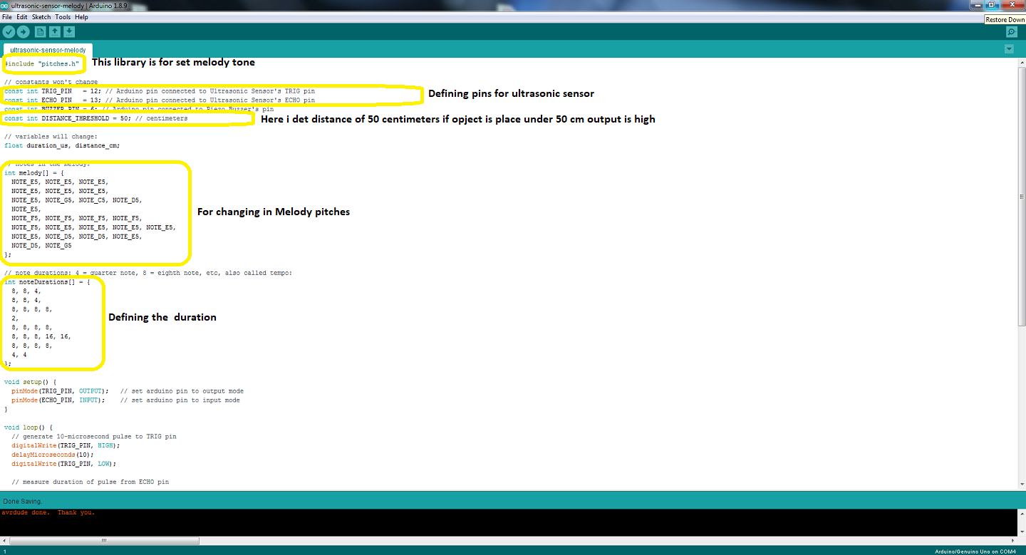
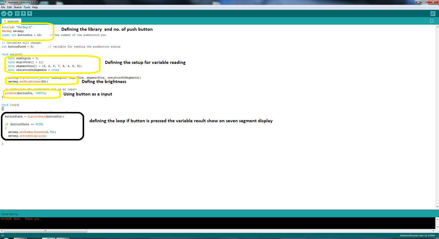
Seven Segment
In general, there are two types of seven segments; one is known as the common anode and the other as the common cathode.

As seen in the figure above, there are two com pins. If the 7 segment is normal anode, the com pin should be 5 volts, and any segment I choose to turn on should be GND. One of the segments forms a closed circuit, causing the segment to light up.


Control Servo with an RFID Tag
I'll use a solenoid lock as an output device in my project, however because the lock isn't available, I'll use a servo motor to place of Solenoid lock. The rfid module is used in my project.
Import library
After connecting the microcontroller to the RFID module, the next move is to download an arduino RFID Library for MFRC522. Take the following steps:
- Step 1.download Arduino RFID Library for MFRC522
- Step 2. Go to Arduino IDE.
- Step 3. Go to sketch -> Include Library -> Add.zip file

Go to files, examples, MFRC22, and Dumpinfo after downloading the library.

GO to tools then click on Serial monitor.

Scane your Tag card. here ID data can be seen.Copy uid card code

Put your uid card number in this box.

Once the programme has been uploaded, the tag will be placed to see if access has been refused.

I use servo motor in the placement of electronic lock due to unavailable in our lab
"Click here"to download all files of this week

