
|

| Sukkur IBA University Merit, Quality, Excellence |
Week - 13
Embedded Networking and Communications
Assignment
Group Assignment
- Send a message between two projects
Serial Communication Between Two Controller
Serial communication on pins TX or RX uses TTL logic levels (5V or 3.3V depending on the board). Don't connect these pins directly to an RS232 serial port; they operate at +/- 12V and can damage your Arduino board. Serial is used for communication between the Arduino board and a computer or other devices. All Arduino boards have at least one serial port (also known as a UART or USART): Serial. It communicates on digital pins 0 (RX) and 1 (TX) as well as with the computer via USB. The two Arduino boards are connected serially. The TX of the Transmitter Arduino is connected with the RX of the Receiver Arduino. The RX of the Transmitter Arduino is connected with the TX of the Receiver Arduino. in the simulation it doesn't matter if you don't connect the grounds of both the Arduino's, but in reality make sure you connect the grounds of both the Arduino's.
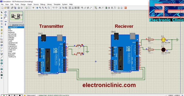
This is connection diagram using proteus simulation I took from this website HERE
TRANSMITTER CODE
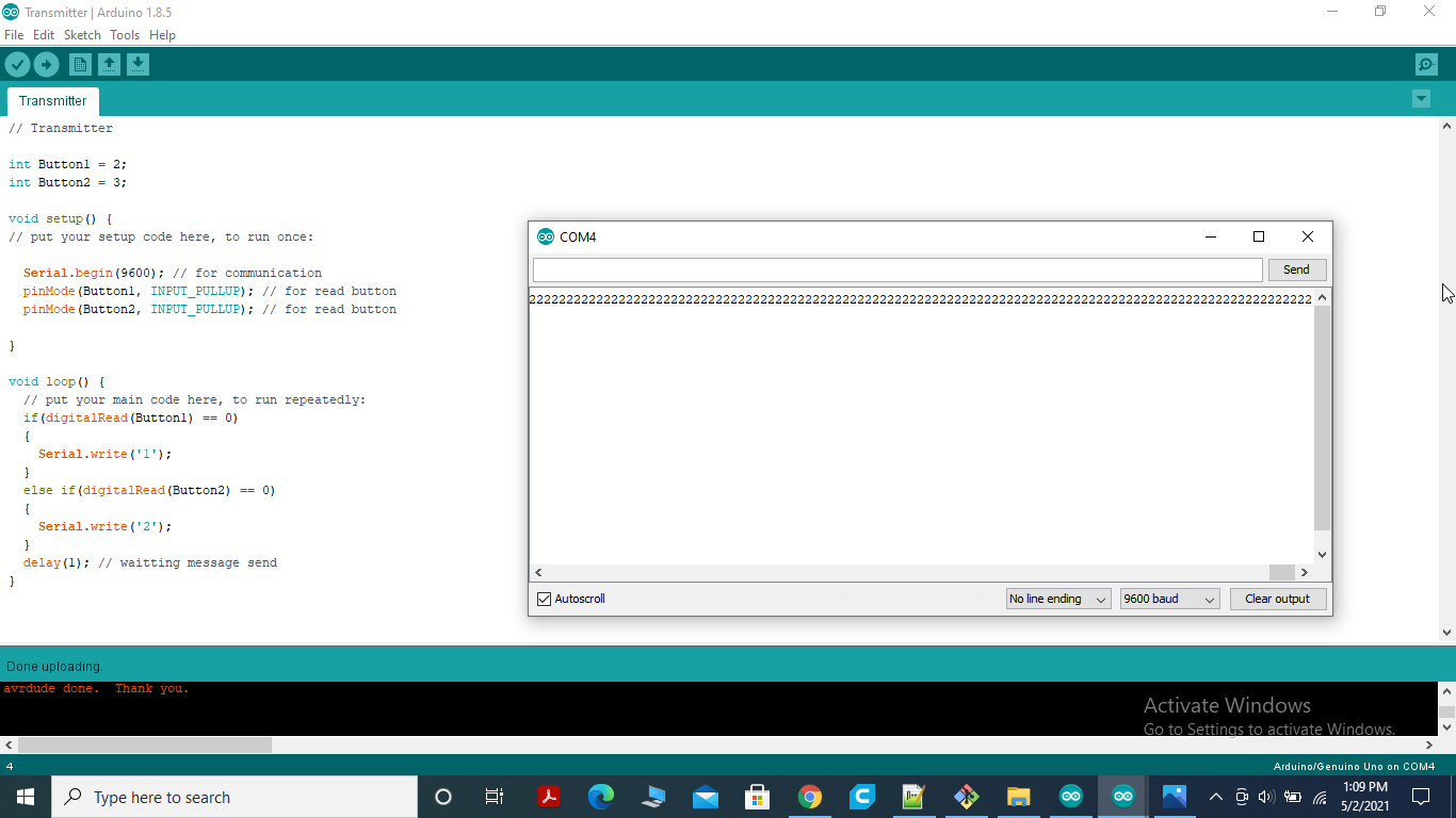
This code is transmit the signal to the receiver using buttons.
RECEIVER CODE
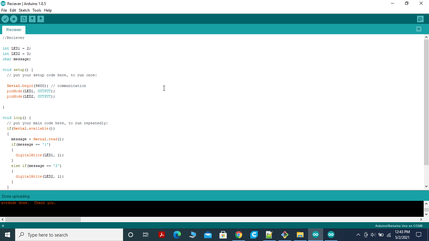
This code receives the signal through Rx from transmitter Tx.
Individual Assignment
- Design, build, and connect wired or wireless node(s) with network or bus addresses
Embedded Communication
The method of transmitting data between two MCUs or from one circuit to another is known as embedded communication. A transmitter and a receiver are needed for communication to take place. There are various classifications based on whether contact is in one direction or both directions; however, the general classification is Synchronous and Asynchronous communication.
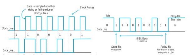
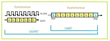
Synchronous refers to the use of the same clock signal by both the sender and the receiver. Before beginning the transfer of each message, the sender sends a synchronisation signal to the receiver.
Synchronous & Asynchronous Data
Communication protocol
Communication is important when working on projects because it allows you to transmit and receive data from and to the Arduino. Furthermore, there are hundreds of protocols for transferring data between an Arduino and other computers over both wired and wireless networks.
Communications protocols cover authentication, error detection and correction, and signaling. They can also describe the syntax, semantics, and synchronization of analog and digital communications. Communications protocols are implemented in hardware and software. There are thousands of communications protocols that are used everywhere in analog and digital communications. Computer networks cannot exist without them.
There are two types of communication protocols which are classified below:
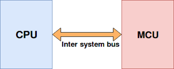
1. Inter System Protocol
2.Intra System Protocol
1.Inter System Protocol:
The inter system protocol using to communicate the two different devices. Like communication between computer to microcontroller kit. The communication is done through a inter bus system.
Different categories of Inter system protocol:
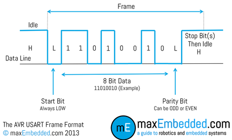
UART Protocol
UART stands for universal asynchronous transmitter and receiver .UART Protocols is a serial communication with two wired protocol .The data cable signal lines are labeled as Rx and Tx. Serial communication is commonly used for transmitting and receiving the signal. It is transfer and receives the data serially bit by bit without class pulses. Ex: Emails, SMS, Walkie-talkie.
USART Protocol
USART stands for universal synchronous and asynchronous transmitter and receiver. It is a serial communication of two wire protocol. The data cable signal lines are labeled as Rx and TX. This protocol is used to transmitting and receiving the data byte by byte along with the clock pulses. It is a full-duplex protocol means transmitting and receiving data simultaneously to different board rates. Different devices communicate with microcontroller to this protocol. Ex:-Telecommunications.
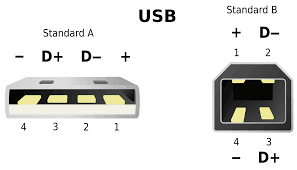
USB Protocol
USB stands for universal serial bus. Again it is a serial communication of two wire protocol. The data cable signal lines are labeled D+ and D-.This protocol is used to communicate with the system peripherals.USB protocol is used to send and receive the data serially to the host and peripheral devices.USB communication requires a driver software which is based on the functionality of the system.USB device can transfer data on the bus without any request on the host computer. Ex: Mouse, Keyboard, Hubs, switches, pen drive.
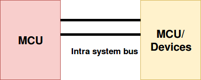
2.Intra System Protocol:
The Intra system protocol is used to communicate the two devices within the circuit board. While using this intra system protocols, with out going to intra system protocols we will expand the peripherals of the microcontroller. The circuit complexity and power consumption will be increases by using intra system protocol. Using intra system protocols circuit complexity and power consumption, cost is decrease and it is very secure to accessing the data.
Different categories of Inter system protocol
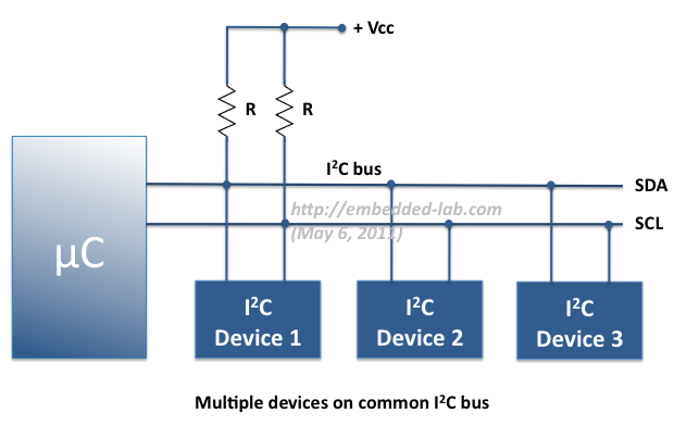
I2C Protocol
I2C stands for inter integrated circuit. I2C requires only two wires connecting all peripherals to microcontroller.I2C requires two wires SDA (serial data line) and SCL (serial clock line) to carry information between devices. It is a master to slave communication protocol. Each slave has a unique address. Master device sends the address of the target slave device and read/write flag. The address is match any slave device that device is ON, remaining slave devices are disable mode. Once the address is match communication proceed between master and that slave device and transmitting and receiving the data.
SPI Protocol
A SPI has a master/Slave communication by using four lines. A SPI can have only one master and can have multiple slaves. A master is usually a microcontroller and the slaves can be a microcontroller, sensors, ADC, DAC, LCD etc.
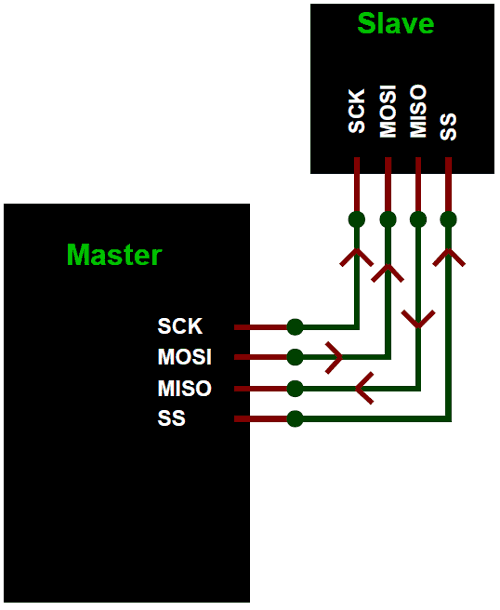
SPI has following four lines MISO, MOSI, SS, and CLK
MISO (Master in Slave Out) - The Slave line for sending data to the master.
MOSI (Master Out Slave In) - The Master line for sending data to the peripherals.
SCK (Serial Clock) - The clock pulses which synchronize data transmission generated by the master.
SS (Slave Select) –Master can use this pin to enable and disable specific devices.
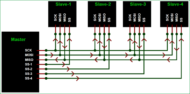
SPI Master with Multiple Slaves
SPI Pins in Arduino UNO
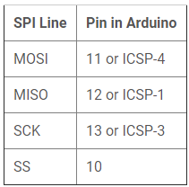
Using SPI in Arduino
Before start programming for SPI communication between two Arduinos. We need to learn about the Arduino SPI library used in Arduino IDE.
The libraryis included in the program for using the following functions for SPI communication.
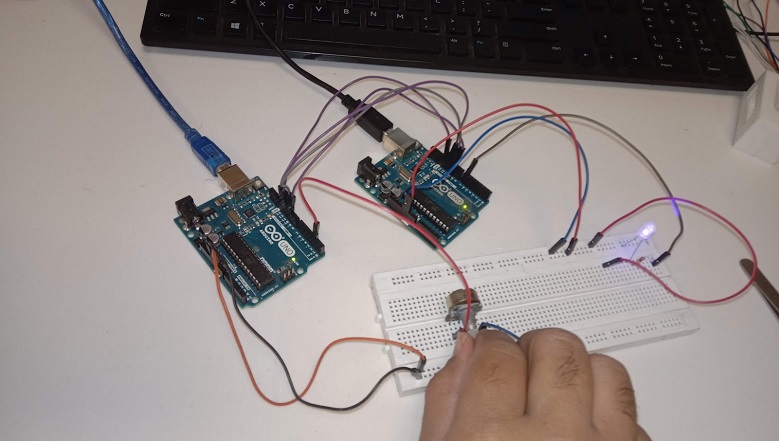
Below is the picture of final setup for SPI communication between two Arduino Boards.
When potentiometer rotate at Master side is pressed, white LED at slave side turns ON.
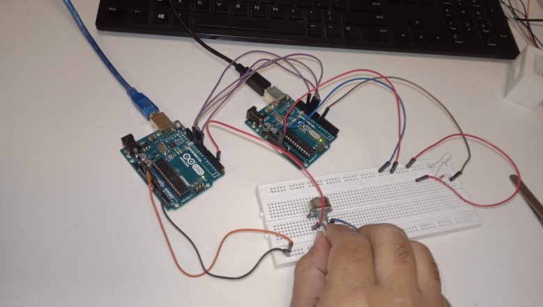
And when the rotate potentiometer at Slave side is pressed, Red LED at Master side turns ON.
"Click here"to download all files of this week