14. Networking and Communications
Assignments
- individual assignment:
- design, build, and connect wired or wireless node(s) with network or bus addresses
- group assignment:
- send a message between two projects
Group Assignment
Here is the page where we documented communication between Raspberry Pi and multiple ESP32s using MQTT.
Individual Assignment
About ESP32
This week I worked with a ESP32 with Wifi and Bluetooth communication.
According to it’s Wikipedia page, ESP32 is a series of low-cost, low-power system on a chip microcontrollers with integrated Wi-Fi and dual-mode Bluetooth (Bluetooth and Bluetooth Low Energy). ESP32 is created and developed by Espressif Systems, a Shanghai-based Chinese company. It is a successor to the ESP8266 microcontroller.
I refered to this tutorial page of FabLab Kamakura.
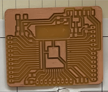
Solder Barduino 2.0
To work on ESP32, I made my own Barduino 2.0 (link) - a ESP32 fabacademy compatible board designed by Eduardo Chamorro Martin with the help of Josep Marti and Oscar Gonzalez in Fab Lab Barcelona 2020.
The board was milled by the instructors, and sent to me since we didn’t have lab access due to the lockdown.
I soldered these components onto the board:
| Component | Specification | Number |
|---|---|---|
| micro controller | ESP32 | 1 |
| resistor | 10KΩ | 1 |
| switch | tact | 1 |
| capacitor | 10uF | 2 |
| regulator | 3.3V, 1A | 1 |
| led | red | 2 |
| resistor | 100Ω | 2 |
| switch | slide | 1 |
| capacitor | 1uF | 1 |
| header | 6pin for FTDI | 1 |
| header | 11pin | 1 |
| header | 13pin | 1 |
The soldering parts are very small on ESP32.
I applied flux onto ESP32-WROOM-32 not only the surface, but the side and all the bottom to cover the electrodes.
For the first pin, I applied solder to the board first, and then soldered ESP32 onto it.
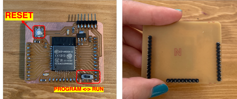
For the headers, I used male pins instead of female pins. I soldered them on so I wire from the bottom of the board.
FTDI cable is connected to the FTDI pins.
The tact switch is for RESET, the slide switch is to change modes between Program and Run.
hello.ESP32-WROOM.echo
I tried to run hello.ESP32-WROOM.echo on Arduino IDE.
//
// hello.ESP32-WROOM.echo.ino
//
// ESP32-WROOM echo hello-world
//
// Neil Gershenfeld 1/6/20
//
// This work may be reproduced, modified, distributed,
// performed, and displayed for any purpose, but must
// acknowledge this project. Copyright is retained and
// must be preserved. The work is provided as is; no
// warranty is provided, and users accept all liability.
//

void setup() {
   Serial.begin(115200);
   }

#define max_buffer 25

void loop() {
   static char chr;
   static char buffer[max_buffer] = {0};
   static int index;
   if (Serial.available()) {
      chr = Serial.read();
      Serial.print("hello.ESP32-WROOM.echo: you typed \"");
      buffer[index++] = chr;
      if (index == (max_buffer-1))
         index = 0;
      Serial.print(buffer);
      Serial.println("\"");
      }
   }
I already had ESP32 installed in my board manager so I skipped the installation process.
I connecred FTDI cable to the FTDI pins, and set the settings to these:
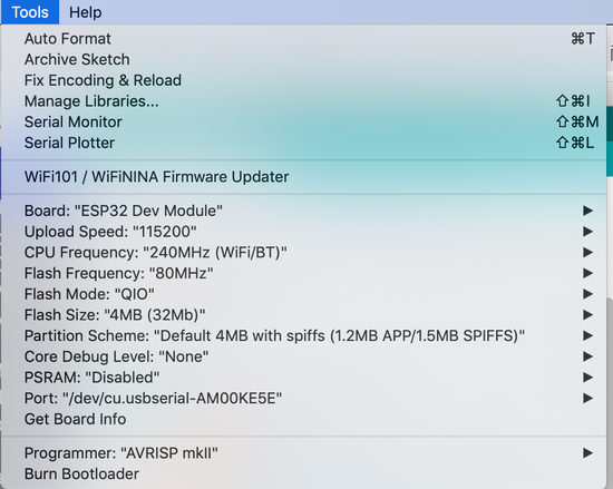
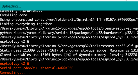
I switched the slide switch to the left (Program), and ran the code.
I pressed the tact switch (Reset) when it shows “Connecting…”.
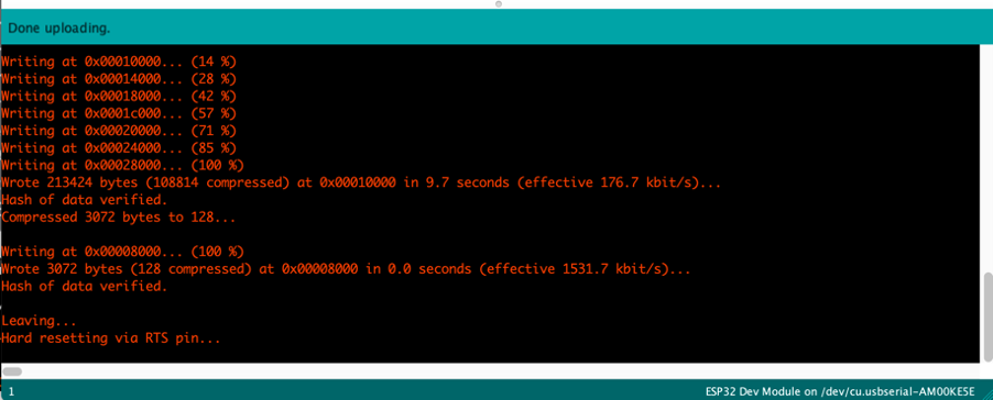
When it showed “Leaving… Hard resetting via RTS pin, I switched the slide switch to the right (Run).
Then I opened terminal, and tried to run this code:
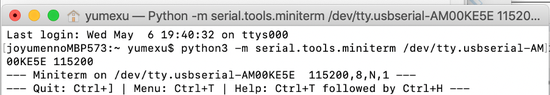
$ python3 -m serial.tools.miniterm /dev/tty.usbserial-AM00KE5E 115200
(“usbserial-AM00KE5E 115200” is the port’s name on my computer.)
However, I got this error:
/Library/Frameworks/Python.framework/Versions/3.8/bin/python3: Error while finding module specification for 'serial.tools.miniterm' (ModuleNotFoundError: No module named 'serial')
I googled and figured that I didn’t have pyserial and esptool on my computer.
I ran $ pip3 install esptool to install esptool.
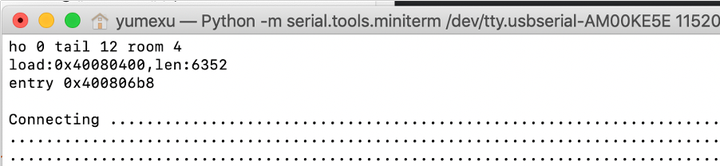
After installing, I ran $ python3 -m serial.tools.miniterm /dev/tty.usbserial-AM00KE5E 115200 again, and got response!
However, it doesn’t respond no matter what I type…
When I hit Reset button, I got message like this:
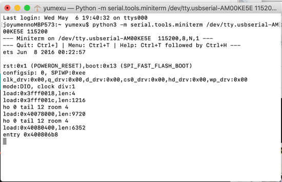
But still doesn’t change the fact that it doesn’t respond…
I changed the board to Program mode and re-ran the program in Arduino IDE.
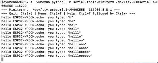
Then I switched to Run, hit Reset, and it responded this time!
The procedure of writing program should always be:
Switch to Program > upload the program using Arduino IDE > hit Reset button (timing doesn’t matter too much as long as it didn’t take too long after Arduino IDE says “connecting…”)
The procedure for running a program is:
Switch to Run > hit Reset button.
Blink
I opened example code for blink on Arduino IDE.
Since LED is connected to pin 13 on this board, I added #define LED_BUILTIN 13 before void setup().
# define LED_BUILTIN 13

void setup() {
  // initialize digital pin LED_BUILTIN as an output.
  pinMode(LED_BUILTIN, OUTPUT);
}

// the loop function runs over and over again forever
void loop() {
  digitalWrite(LED_BUILTIN, HIGH);   // turn the LED on (HIGH is the voltage level)
  delay(1000);                       // wait for a second
  digitalWrite(LED_BUILTIN, LOW);    // turn the LED off by making the voltage LOW
  delay(1000);                       // wait for a second
}
I tried to run the program, but got an error message like this:
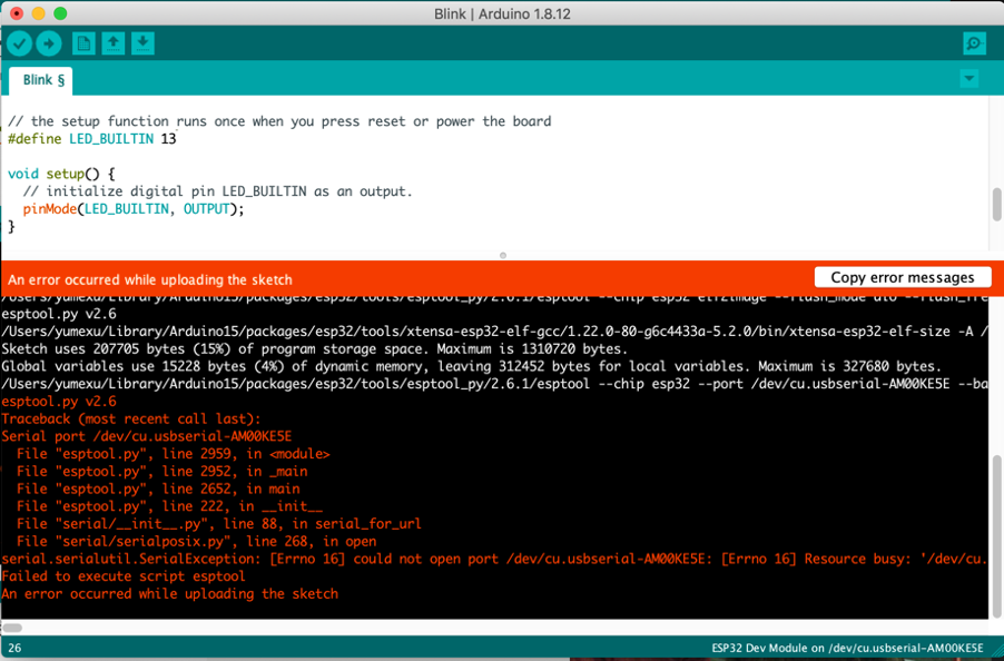
I wasn’t able to find the way to solve it by searching, so I replugged ESP32 to the FTDI cable, made sure the switch was on Program, hit Reset, and ran the code again.
It actually worked this time!
Wifi communication using Blynk
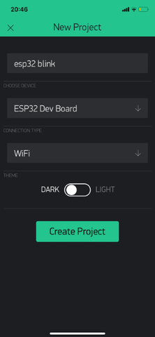
I tried using Blynk on my iPhone to control the board through Wifi communication.
Set up on Blynk
After installing the app, I pressed “New Project” on the app, chose “ESP32 Dev Board” as the board, and “Wifi” as the connection type.
After creating the project, the app told me that it sent me a token to my registered email address.
Touch any blank space on the screen and Widget Box shows up.
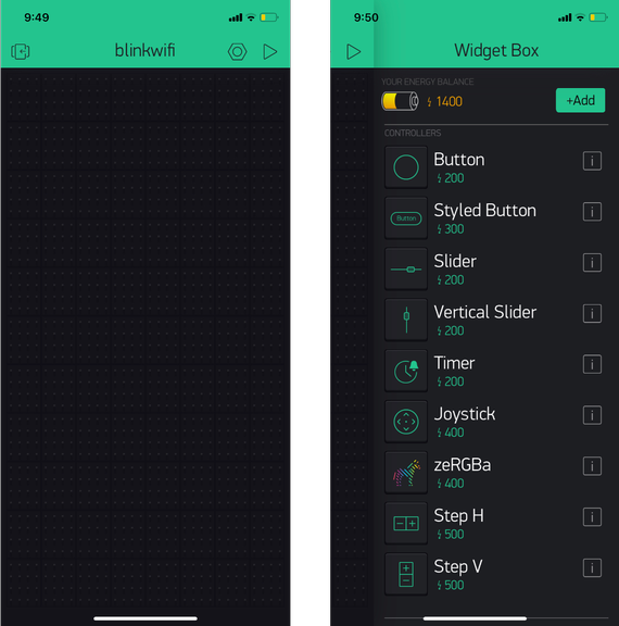
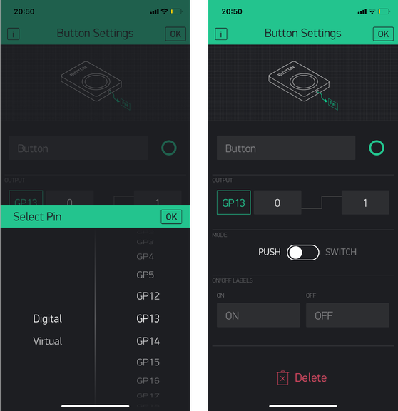
After choosing Button, I set the pin to Digital DP13 since the LED is connected to it.
Run the code
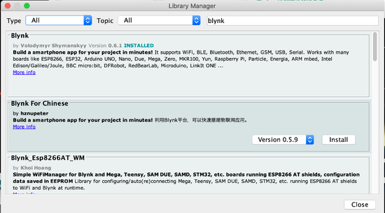
I followed the instructions on this page to install Blynk library on Arduino IDE.
I opened Arduino IDE > Library manager through Sketch > Include Library > Manage Libraries.
I searched for Blynk and installed the one coming to the top.
And I opened the sketch through Arduino IDE > Files > Examples > Examples from Custom Libraries > Blynk > Boards_WiFi > ESP32_Wifi, and replaced “YourAuthToken” with my actual Token(the one sent to my email address from Blynk) , “YourNetworkName” with my Wifi SSID, “YourPassword” with my Wifi password.
#define BLYNK_PRINT Serial


#include <WiFi.h>
#include <WiFiClient.h>
#include <BlynkSimpleEsp32.h>

// You should get Auth Token in the Blynk App.
// Go to the Project Settings (nut icon).
char auth[] = "YourAuthToken";

// Your WiFi credentials.
// Set password to "" for open networks.
char ssid[] = "YourNetworkName";
char pass[] = "YourPassword";

void setup()
{
  // Debug console
  Serial.begin(9600);

  Blynk.begin(auth, ssid, pass);
}

void loop()
{
  Blynk.run();
}
After writing the program, switing to Run mode, I was able to control the LED on my Barduino 2.0 through my phone!
Bluetooth Low Energy (BLE) communication using Blynk
BLE is a type of Bluetooth communication. According to this page, it supports devices using not too much energy. Since it does not consume much energy, it saves the battery life.
I refered to this Japanese page to set up.
Set up Blynk
I created a new project with BLE. And added a button and BLE.
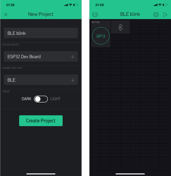
When tapping the BLE logo, the device didn’t show up since the setup on ESP32 was not done.
Run the code
I opened the sample code through Arduino IDE > Examples > Blynk > Bluetooth board > ESP32_BLE.
And wrote the program onto ESP32.
/*************************************************************
  Download latest Blynk library here:
    https://github.com/blynkkk/blynk-library/releases/latest

  Blynk is a platform with iOS and Android apps to control
  Arduino, Raspberry Pi and the likes over the Internet.
  You can easily build graphic interfaces for all your
  projects by simply dragging and dropping widgets.

    Downloads, docs, tutorials: http://www.blynk.cc
    Sketch generator:           http://examples.blynk.cc
    Blynk community:            http://community.blynk.cc
    Social networks:            http://www.fb.com/blynkapp
                                http://twitter.com/blynk_app

  Blynk library is licensed under MIT license
  This example code is in public domain.

 *************************************************************
  This example shows how to use ESP32 BLE
  to connect your project to Blynk.

  Warning: Bluetooth support is in beta!
 *************************************************************/

/* Comment this out to disable prints and save space */
#define BLYNK_PRINT Serial

#define BLYNK_USE_DIRECT_CONNECT

#include <BlynkSimpleEsp32_BLE.h>
#include <BLEDevice.h>
#include <BLEServer.h>

// You should get Auth Token in the Blynk App.
// Go to the Project Settings (nut icon).
char auth[] = "YourAuthToken";

void setup()
{
  // Debug console
  Serial.begin(9600);

  Serial.println("Waiting for connections...");

  Blynk.setDeviceName("Blynk");

  Blynk.begin(auth);
}

void loop()
{
  Blynk.run();
}
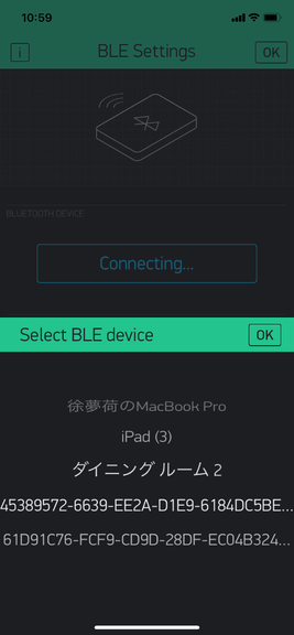
I was able to find the device “Blynk”, but got an error saying “Can’t connect. Please check authentication token.” when I try to connect to it.
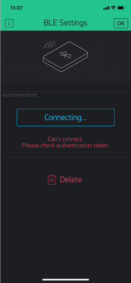
I realized that I need to substitute “YourAuthToken” with the token sent to my email address.
I substituted it and was able to connect with “Blynk”!
I was able to control the LED on the board via BLE communication.
Set up ESP32 as wifi server
I tried to set up ESP32 as a wifi server.
I ran the sample code from Neil on ESP32, entering the correct Wifi SSID and password.
//
// hello.ESP32-WROOM.WebServer.ino
//
// ESP32 Web server hello-world
//
// Neil Gershenfeld 11/12/19
//
// This work may be reproduced, modified, distributed,
// performed, and displayed for any purpose, but must
// acknowledge this project. Copyright is retained and
// must be preserved. The work is provided as is; no
// warranty is provided, and users accept all liability.
//

#include <WiFi.h>

const char* ssid = "your SSID goes here";
const char* password = "your password goes here";
WiFiServer server(80);

void setup() {
  Serial.begin(115200);
  printf("\nConnecting ");
  WiFi.begin(ssid,password);
  while (WiFi.status() != WL_CONNECTED) {
    delay(100);
    printf(".");
    }
  printf("\nConnected with address %s\n",WiFi.localIP().toString().c_str());
  server.begin();
  }

void loop() {
  char cold,cnew;
  WiFiClient client = server.available();
  if (client) {
    printf("\nReceived connection from %s\n\n",client.remoteIP().toString().c_str());
    while (client.connected()) {
      if (client.available()) {
        cnew = client.read();
        printf("%c",cnew);
        if ((cold == '\n') && (cnew == '\r')) { // check for blank line at end of request
          client.printf("HTTP/1.1 200 OK\n");
          client.printf("Content-type:text/html\n");
          client.printf("\n");
          client.printf("Hello %s from ESP32-WROOM!<br>\n",client.remoteIP().toString().c_str());
          client.stop();
          break;
          }
        cold = cnew;
        }
      }
    }
  }
Then I opened terminal and ran this line $ python3 -m serial.tools.miniterm /dev/tty.usbserial-AM00KE5E 115200.
At first it continued to show “Connecting .........”.
Then when I pressed Reset button, it continued to show the IP address.
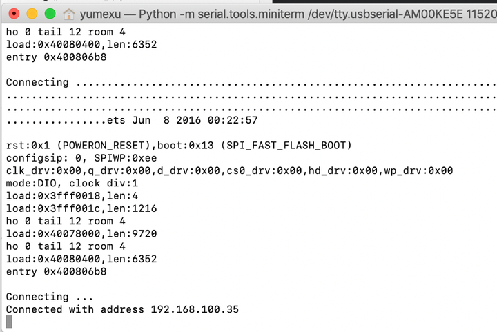
I entered the IP address into a web browser, and it showed message: “HELLO (IP address) FROM ESP32-WROOM!”.
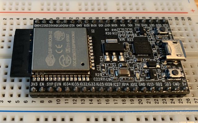
Work with ESP32_core_board_v2
ESP32_core_board_v2 is a development board.
I wanted to get this one to work, and someday have it communicating with my Barduino 2.0.
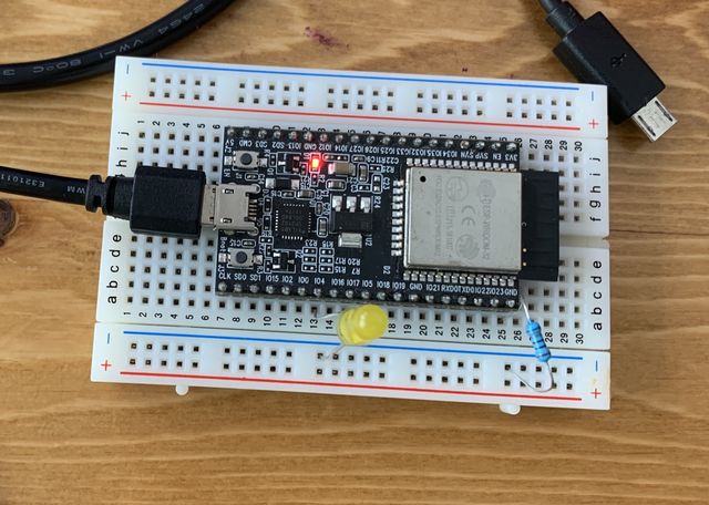
I connected an LED and a resistor, and tried to run the same blink program from before.
However, I got an error message:
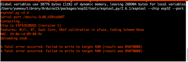
Even if I tried to change the Upload speed to 921600, there was still the same error message.
According to the guru Yamamoto-san in Kamakura, the error might indicate that the board itself was broken.
Re-solder ESP32_core_board_v2
So with the vague hope, I tried to resolder all joints between the legs of the chip and the board.
Since non Pb solder was used in this, I had to set the soldering iron to 380 degree C to actually melt the solder.
After the struggle, I tried to run the code again.
At first, at upload speed 115200, I got the same error message, but when I changed to 921600, it actually went through!!
Wow, did I just fix an existing product????
Comparing BLE and wifi communication
Here is a comparison between communication using Wifi and BLE based on my experience and some research:
-
Speed for connection establishment procedure and data transfer: BLE takes about 3 ms which is very fast, while wifi takes longer, and is dependent on the wifi connection.
-
Data rates: BLE supports 1 Mbps & 2 Mbps data rates while wifi supports up to 150 Mbps.
-
Wireless communication distance: BLE supports up to 200 meters in LOS (Line of Sight) while wifi supports up to 10 km.
-
Power consumption: BLE consumes so much less power than wifi, hence battery life can be very long. This is due to the fact that both master and slave devices can go to deep sleep mode between transactions. Master informs slave about hopping sequence and when to wake up.