Input Devices
group assigment
probe an input device's analog levels and digital signals
individual assignment
measure something: add a sensor to a microcontroller board that you have designed and read it
group assigment
Upadte 06/07/21
you can find what we did on the group assignment here
individual assignment
for this assginment in particular i only did a simulation on tinkerCAD of an arduino conected to a 4X4 keypad however i record my screen doing so and then uploaded to youtube
so this is all....
nahhh, just messing.
i will narrate all that i did here 'cause my video tutorial is completly silent.
the doorstep of the rabit hole
first, open tinkerCAD it is a browerbased simple but really handy CAD tool that can simulate simple circuits like the one i did. you can open thinkerCAD from here
after logging in with your autodesk account and choosing your language of your region you can do tutorials of the CAD tools and so but we are going for the real stuff right away
go to your dashboard
 this is your tinkerCAD design dashboard
then select circuits and create a new circuit
 this is your tinkerCAD circuit dashboard
now you give the project a name in the upper left corner of the browser
just click edit and enter
 here you can rename your project
now, in the right side of the window you can click and drag components
just try draging an arduino uno and a 4X4 keypad for this example
 here you can drag components on the working space
now let's put some wiring on to the board
if you hover the mouse over the pins of the keypad it will show you wich row or column corresponds to
to place a wire you only have to make a left click on the pin on the kleypad you want to wire and other click on the pin of the arduino you want to hook it up (you can also make intermediate click and bend the wire to rout it better
then to change the color or the wiring you can make a click on the wire and assign it a color
 wiring diagram
once the wiring is nice and tiddy it's time to code it
to start coding you only have to click on the code button on the right side of the window
since we're only wi¿orking with text let's select that option and click in continue to hide the block option
 click on coding and then text options
now delete all the premade text to start a sketch from scratch
to save some time you can download my code from here and tweek it as much as you like
then copy and paste all the code in here
 pasete here the code on the link i just gave
once you have all the code click on the start simulation button next to the coding button
this will compile and simulate the arduino running the program
open the serial monitor above all the code
 click on start simulation
now if you click on one button on the keypad it will return the value on the serial monitor like this
 serial monitor working
you can exit the project by clicking on the tinkerCAD logo on the upper left corner
i hope to be milling a circuit on the roland to simulate all this once the COVID-19 quarantine is over
Update 13/07/21
Individual Assignment
All of the following assignment should be updated similarly to meet the requirements of fabacademy
i just did what i could with the tools i had at the moment during COVID-19 lockdown.
that's why i used third parties DEV boards and simulators.
i shall change input devices, output devices, networking and communications and interface and applications.
What i did?
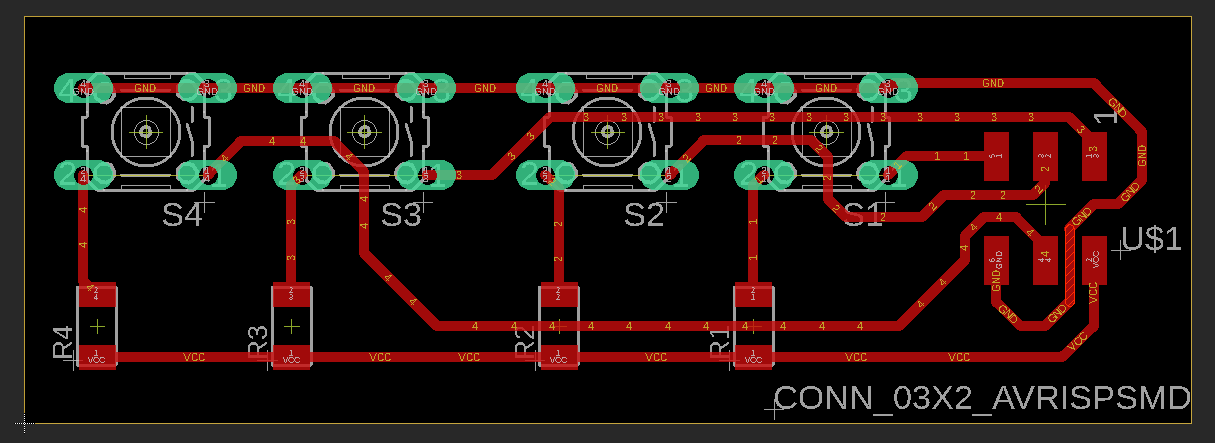
i designed a button pad


Why?
because that should be the input for my program to interact with the menu.
How it works?
i'ts a modular board so there is not a MCU attached to it. So it could work with whatever microcontroller board with an isp port available to conect.

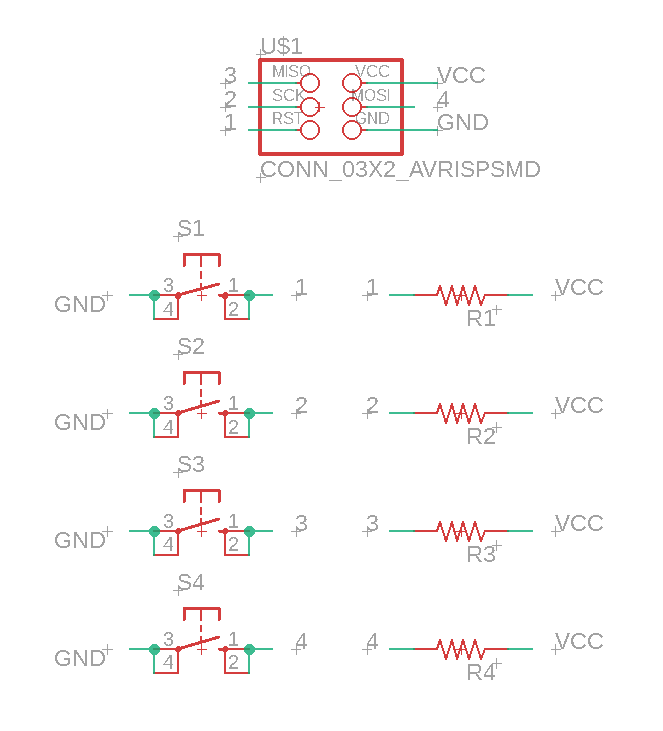
this is the schematic for this assignment

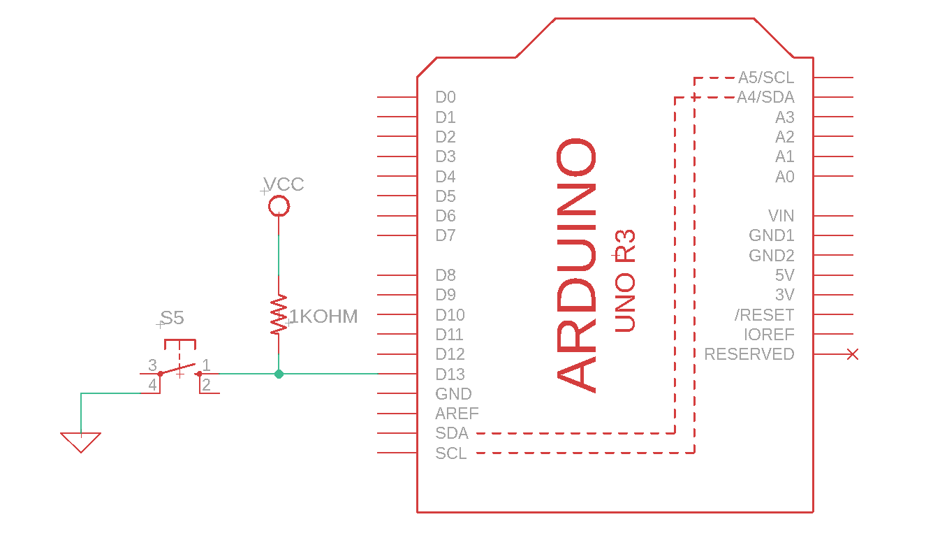
diagram on the basics of a pull up resistor
I added a pull up resistor in every signal pin just to avoid any misreaddings on the microcontroller.
it has 6 pins
One for a power supply, one for a ground reference and one for each button (4 in total).
In the final project developement page you can see what i did on the diferent versions of this board.
i'm sorry i do not have any video to push here but the HDD on my PC is about at 90% capacity by now.
As always i did the design on EAGLE, the toolpath generation on Vcarve pro and the fabrication on the ROLAND SRM-20 in ourlab and HERE are the files
LINKS AND REFERENCES
HERE you can download the fabrication files of the board i did on input devices week (vcarve,highdef images, srm-20 files, sch & brd files)
HERE you can check the developement of my final project.
HERE My youtube channel