3D scanning and printing

group assignment

test the design rules for your 3D printer(s)

from here you can see what we did on the group assignment

individual assignment


This assignment has diferent parts
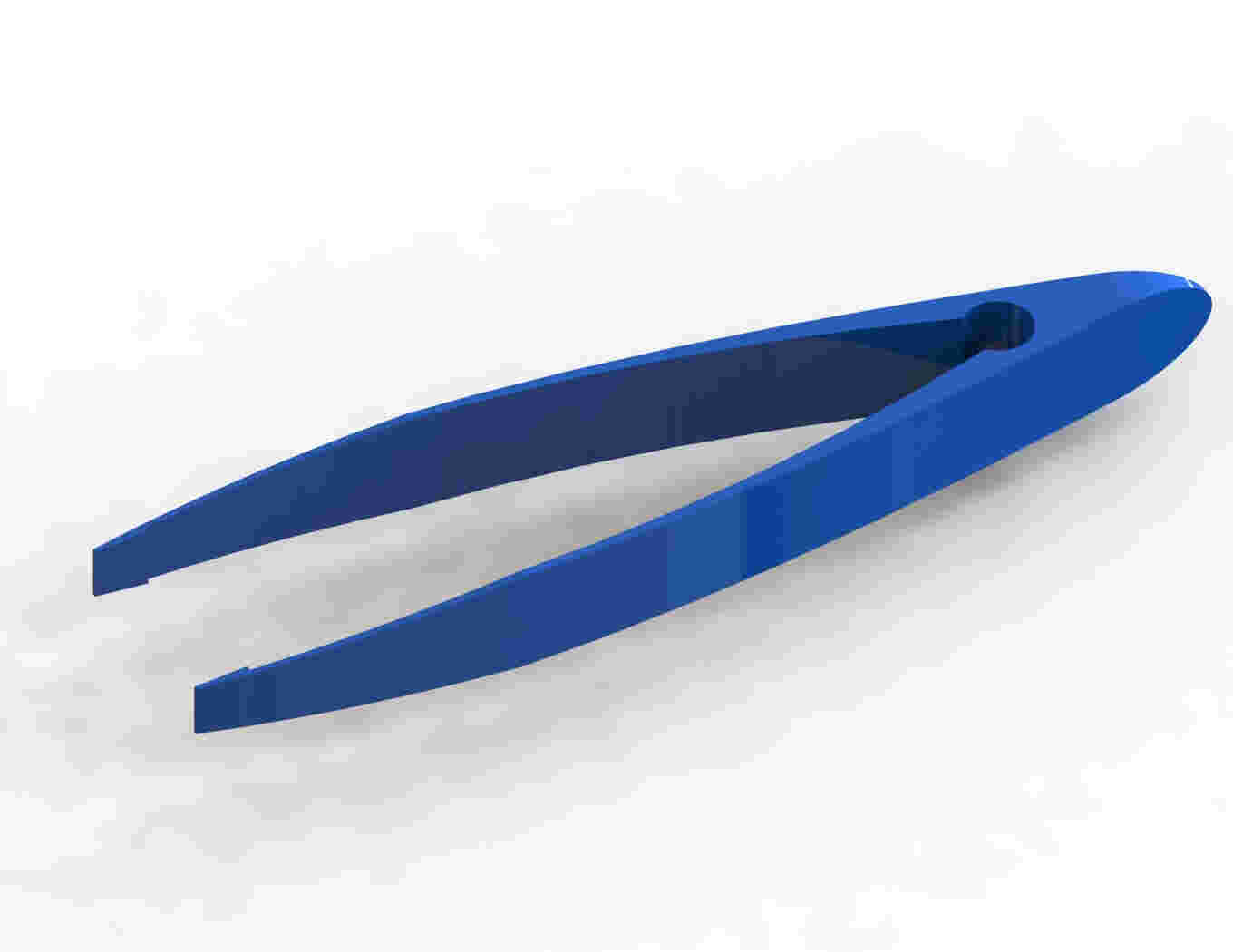
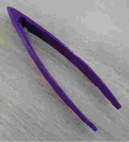

About the tweezers

A little more back ground

As a mechanical electrical engineer for a while now i've been obsesed with compliant mechanisms aditively manufactured in general.

a compliant mechanism is a flexible mechanism that achieves force and motion transmition through elastic body deformation.

usually the tweezers that are electronical/static free purpouse are made of stainless steel or carbon steel coated so it may be a little less magnetic

this tool in particular are assembled from a sheet of metalic low carbon steel from a die cut process then are spot welded or ultrasonic welded

this makes the process expensive and hard to purchase

What i choose?


for the individual asssignment i choose an easy replaceble tweezer using polylactic acid PLA as it is the most common and cheap printable material.

why i choose it?

as i became comforable enough with the smd soldering process. i struggle a lot with getting my hand on a cheap tweezer that can help me to hold the resistors and another smd components while i solder them. among other issues.

sustractive vs. aditive

maybe somebody will say that die cut is a sustractive process (and it may be right if only uses die cut to manufacture a product) but the entire process of the tweezer includes spot welding wich i think it may count as an aditive process.

so sumarized the commercial tweezer may not be able to exist without any of this two processes.

the scope of this assignment was to aditibly produce something that wasn´t able to produce sustractivly.

if i went to an industrial workshop to carve the metalic version of my tweezer in a cnc milling machine.

probably i would be laughed at my face because all of the trouble it has to be to carve out maybe 95% of the material of the stock just to hold an smd component.

As a lab tech on fablabqqro i'm against printing knicknacks that ends up in the garbage bin.

back to index

About the modeling software


So i modeled a pair of tweezers for smd components using solidworks


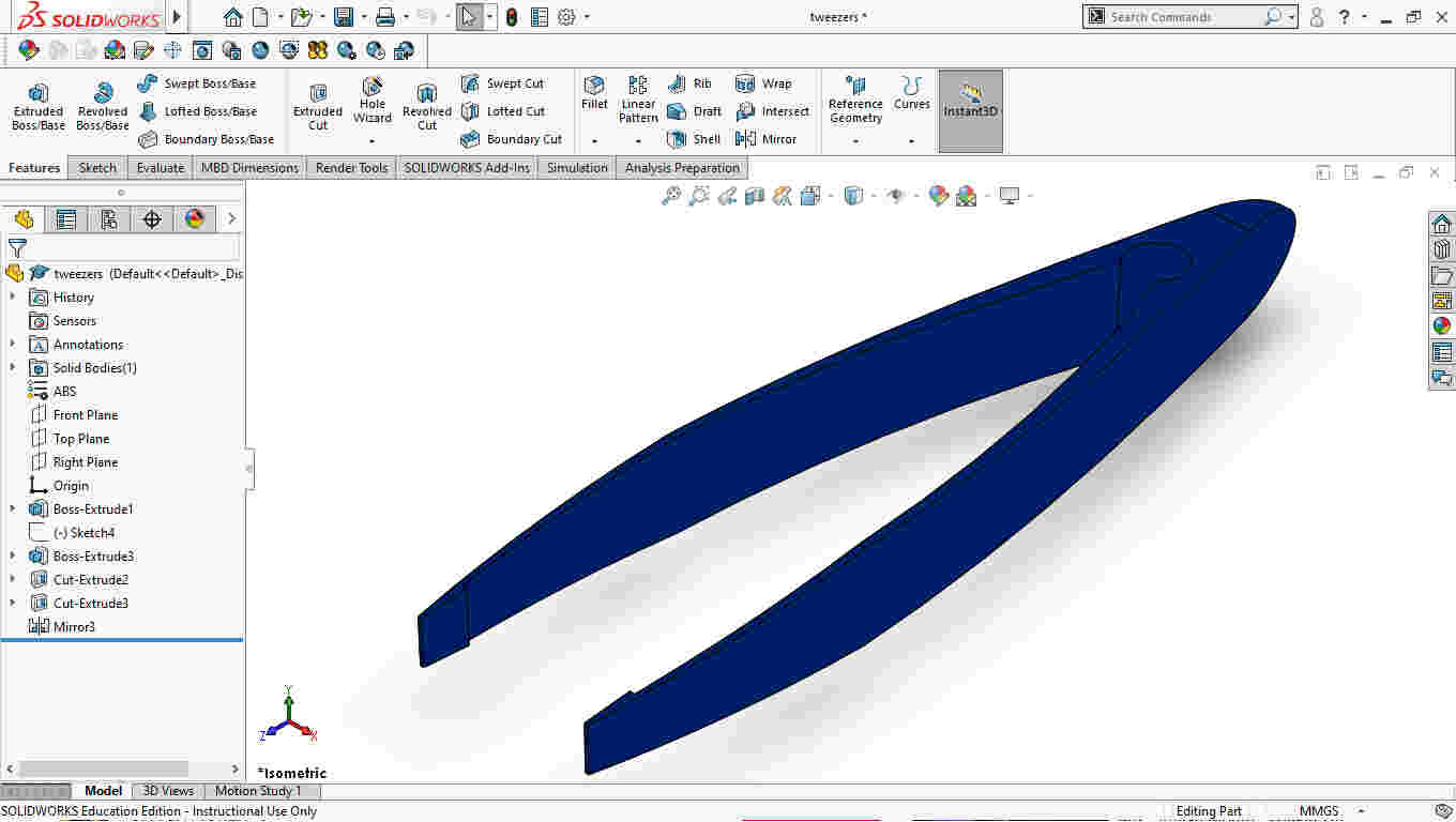
picture directly taken from solidworks


i used some basic geometrical constraints and dimensions considering the diameter of the extrusor wich is about 0.4 mm using expresions on solidworks


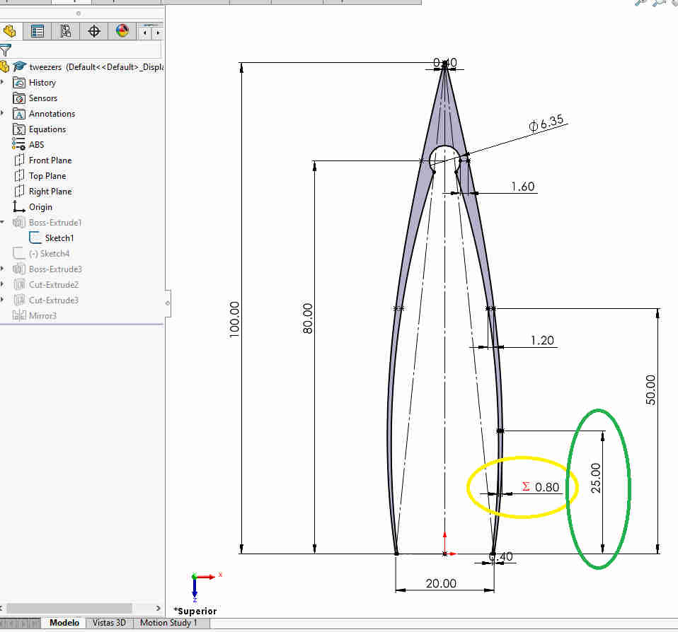
this is a pic from the first sketch

i just wanted to control the diammeter of the nozzle wich i'm using to print it.


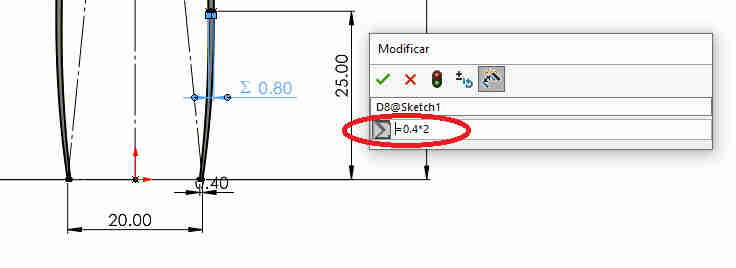
this is a pic on how i parametrized the value i wanted

then i wanted that the hole of the tweezer were at 80% of the overall length


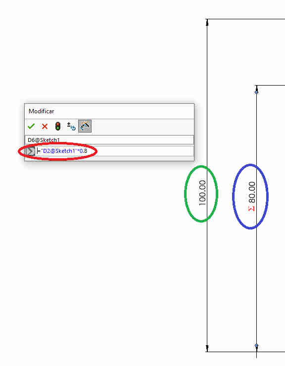
this is how you make a dimension referenced from another dimension


the entire operations tree in solidworks is really simple as you can see.
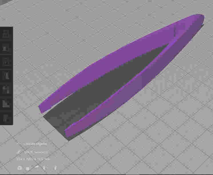
if you can read this i messed up

this low resolution renderized picture looks really bad but it had to be compressed in order to be hosted in my repo.

Back to the index


about the slicer


then i imported into ultimaker's slicer software named cura

HERE you can download the most recent version of ultimaker's cura


piece imported into cura


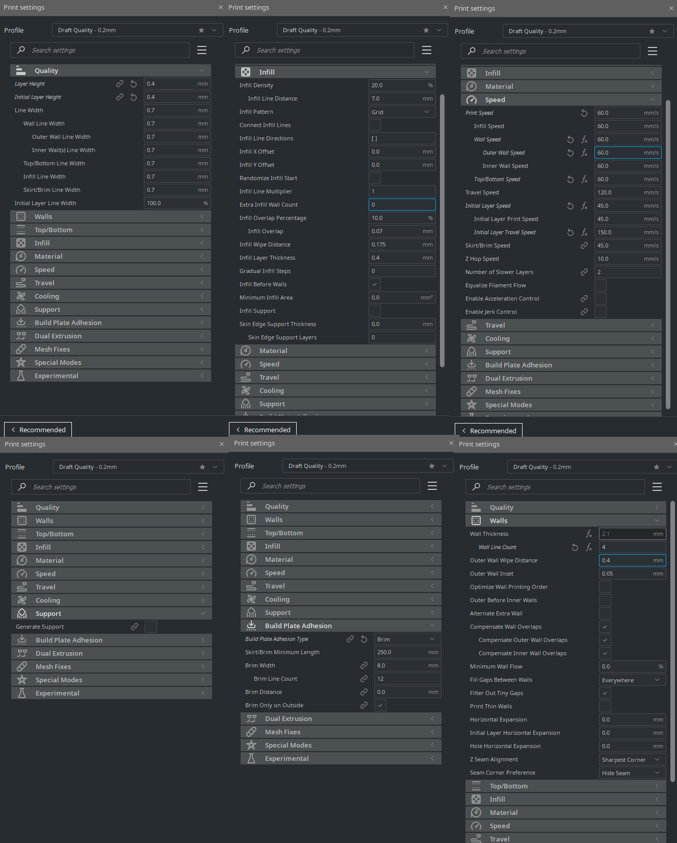
where i twitched a little the default presettings to rush it a little, i set the layer height to 0.2 mm the speed to 60 mm/s and 10% infill.In the future i'd like to experiment with the formalbs flexible resin to make a 3 fingered gripper using the same principle of compliant mecanisms


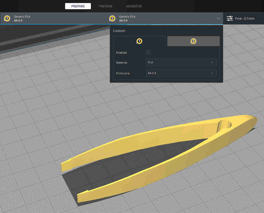
this is a screenshot if all of diameter of the nozzle i used to print this


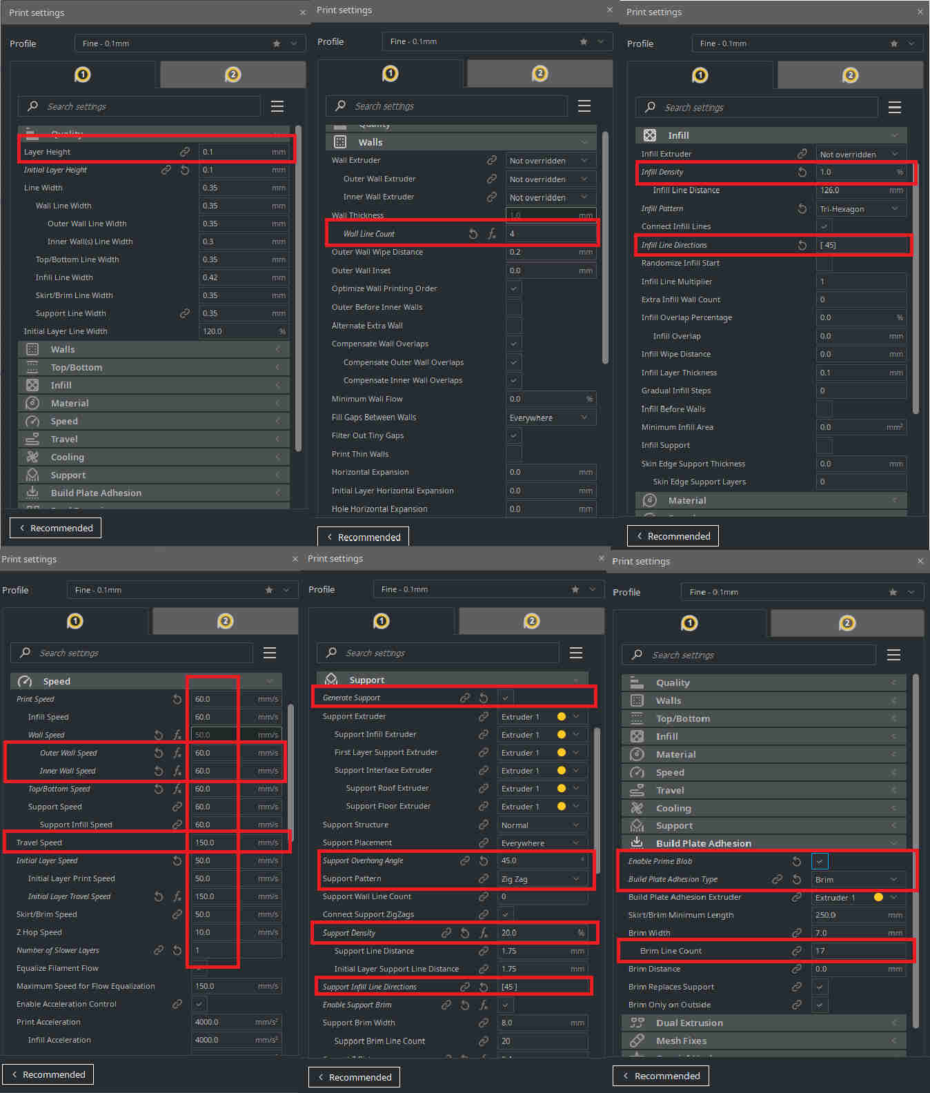
this is a screen shot of the parameters i used on the ultimaker 5s we have in the lab.

because the tweezer has to hold motion and forces y cranked up the perimeters and got really low on the infill.

sliced part


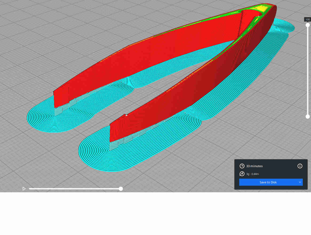
after setting the parameters i clicked on the slicer button and saved it as G-code

here you can download my G-code

HERE you can download all of the files (solidowks native,stl,g-code for ultimaker)from the tweezer


then set the printer making the tweezer
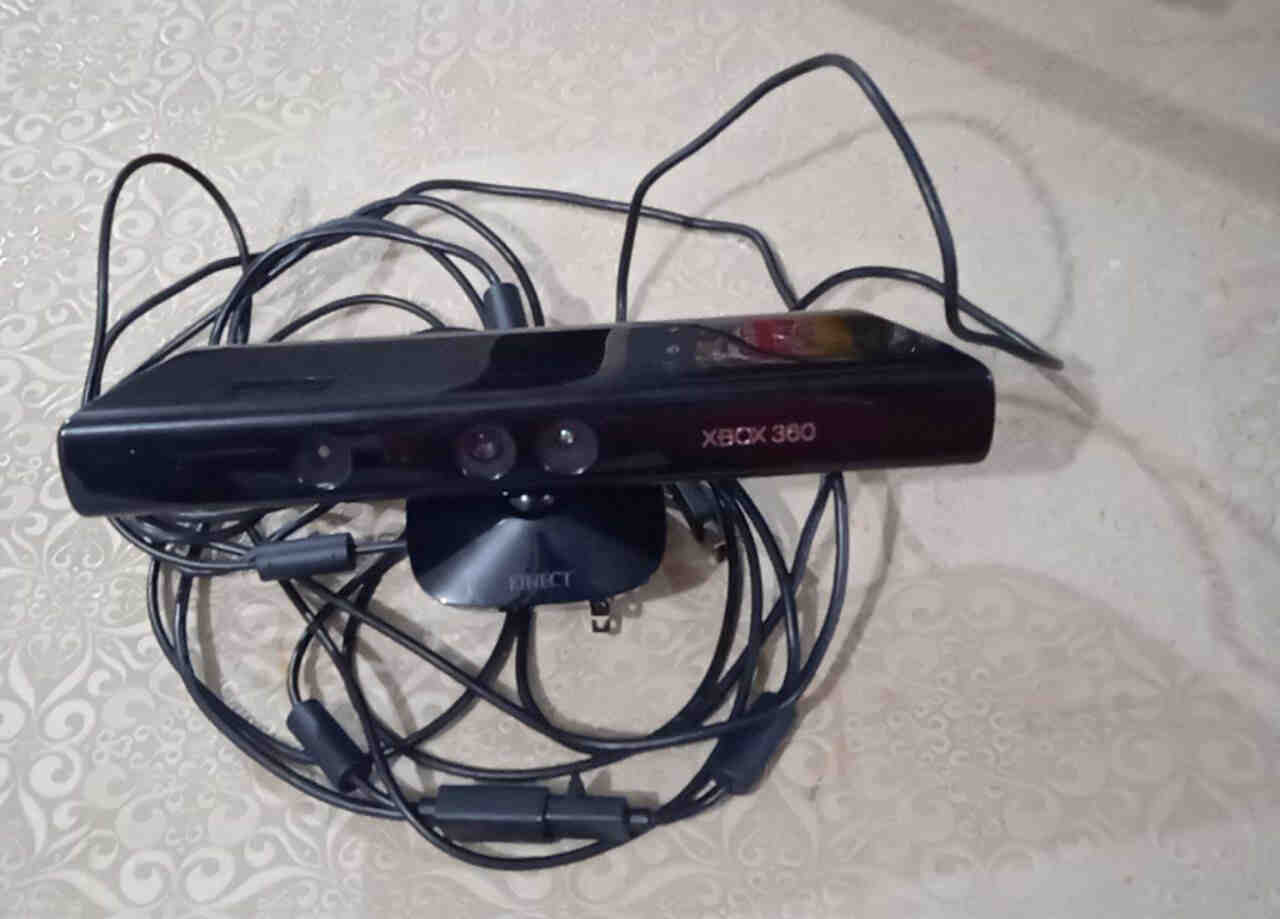
if you can read this i messed up

here is the final piece

It work as it was intended but. if i press just a little harder than i should then the resistor goes flying away from the table.

i think that i may repeat the experiment using another material and setting the thinest part a little bit higher than 25%. y may be stiffer.

Back to index


About the scanner


For this part of the assignment i used the microsoft kinect and usb adapter to 3D a printed part that i had near and made a video tutorial out it however i previously installed the kinect driver and a software called skanect that has a really nice freemium version. here you can go to download the driver i used on windows 10

here you can download skanect software


HERE you can download all of the scaning project files


this is the scanner i used for this assignment just an ordinary kineckt 360 from microsfot and a usb adapter to plug it in to the power supply and the laptop.

a litle step by step tutorial


after i installed the skantec software and plug in the kinekct into the pc the next step is to start scanning.

if you can read this i messed up

skanect's firts tab "prepare"


Basically is a four step process you start by informing the software the size of the object you are scanning


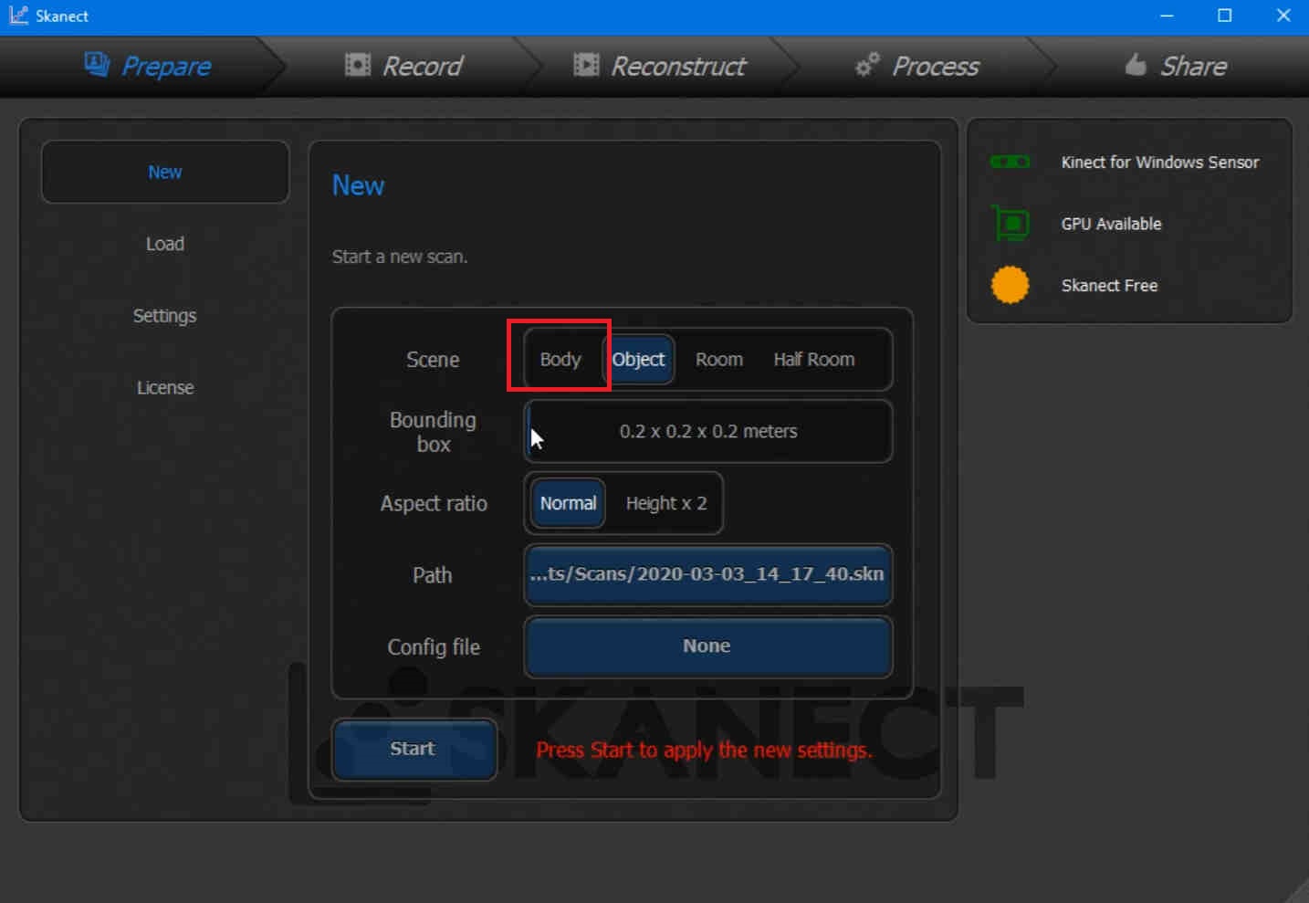
since we´re running the free version of the software we are just using object for this tutorial

in the video at the endo of the tutorial i used body because it picked a lot of random stuff arround my house


skanect's record tab


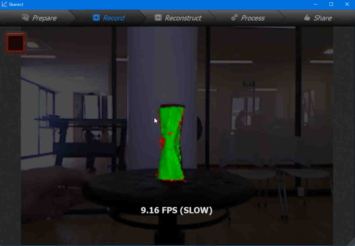
after that you should start recoding the scan while you rotate the object in front of the scanner.


For this step it is important not to move arround the object to much and rotate it slowly i used an office stool for this.


skanect's third tab


in this step you are going to indicate the software where you want to reconstruct the model using the CPU or the GPU memory.


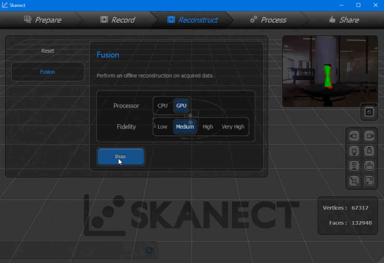
since i was using an alienware laptop i choosed GPU.


skanect's last tab


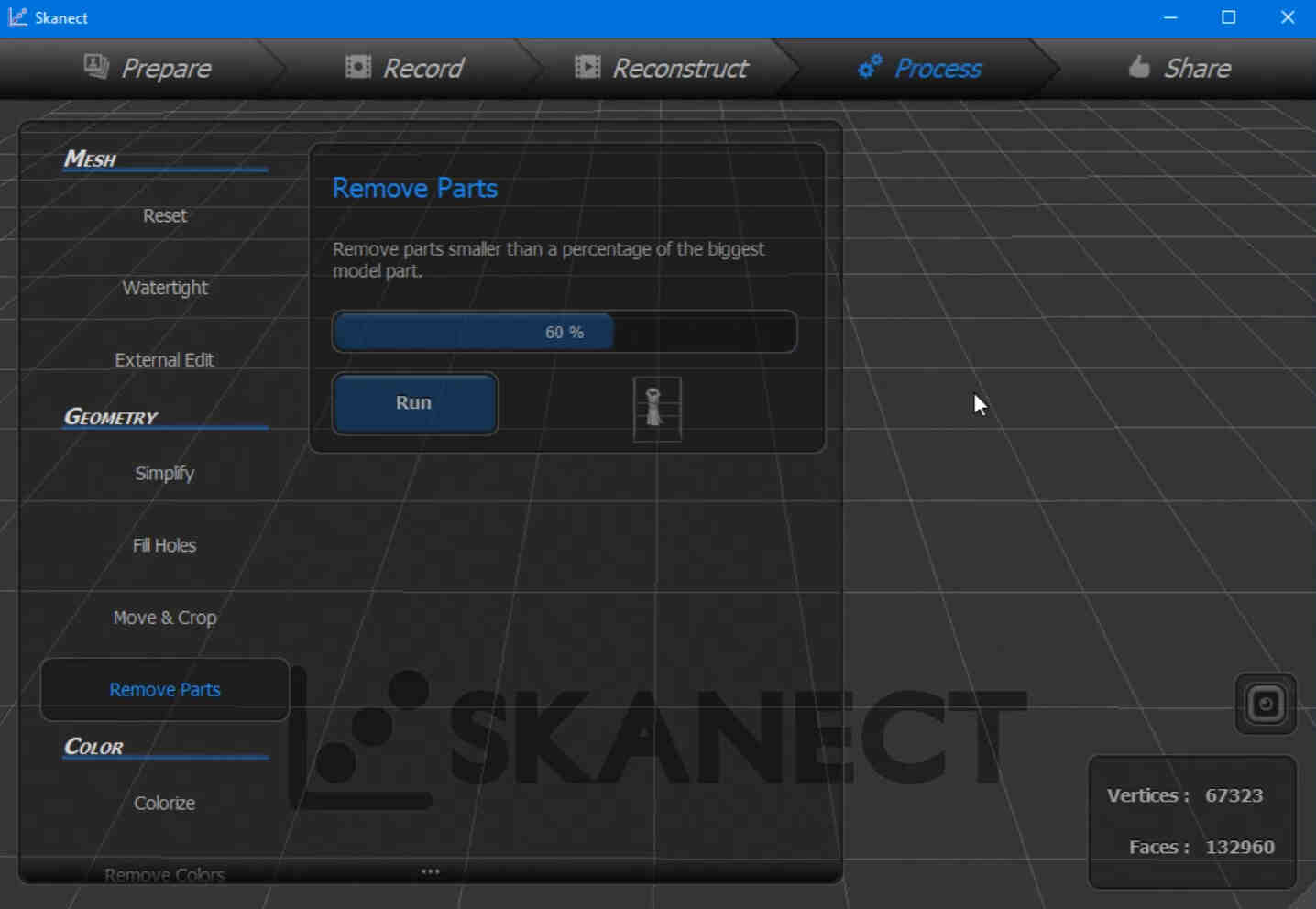
and here you'll tell the software. that you want a watertigh obj, stl,ply or anotherfile type


since this is just a tutorial i selected a stl in millimeters.


this video is hosted from my youtube account


and this video is hosted on my repo.
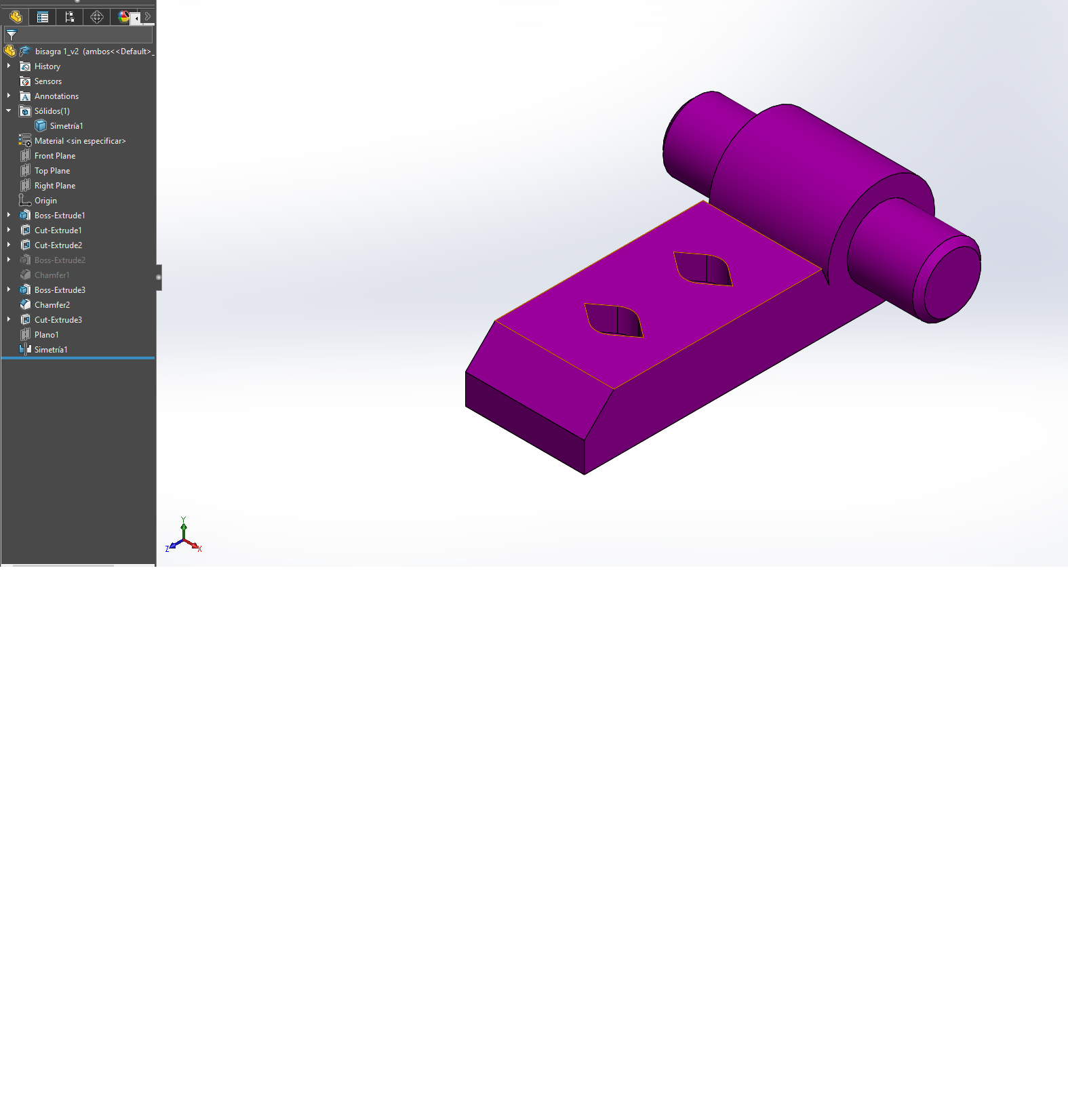
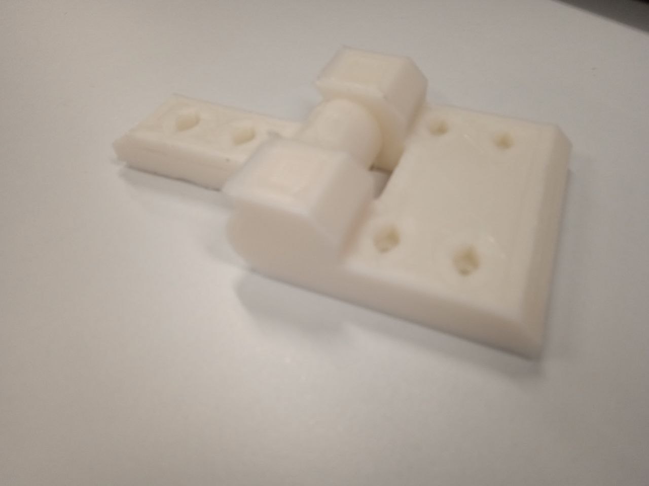
Back to index


About the hinges

as part of the global evaluation i'm pushed to explain a little bit more about this simple hinge printed for my final project but a little bit tweeked to be printed in one go.


female part

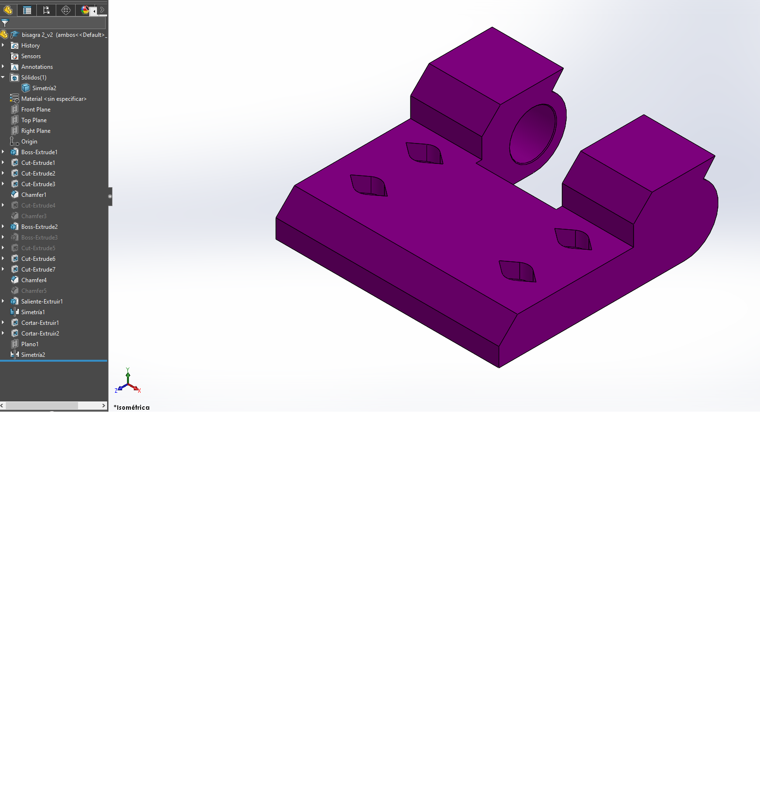
just used a mirror feature in solidworks just to make it symetric.


male part

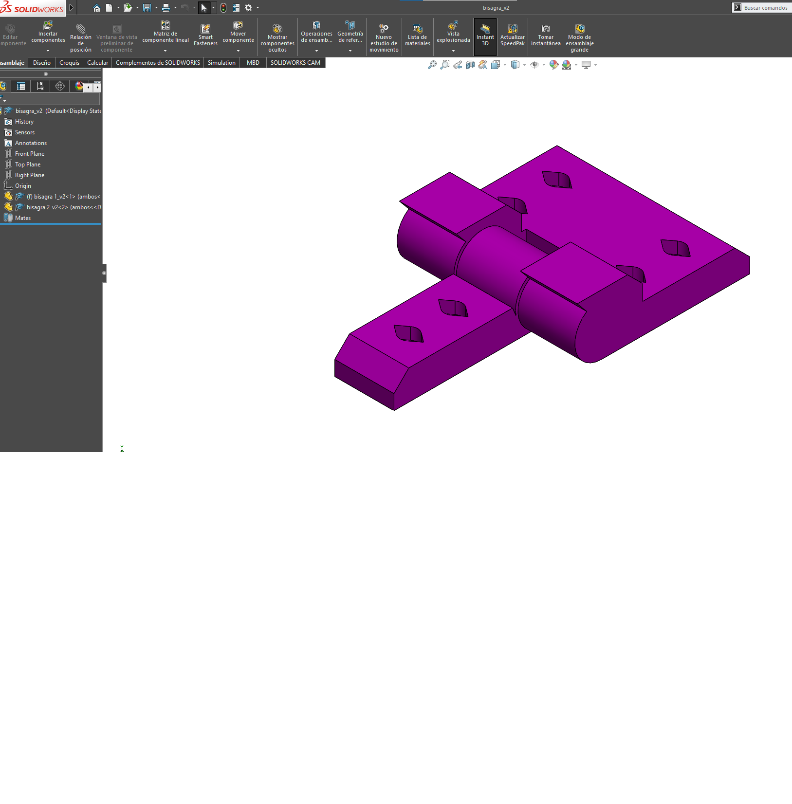
also with theese i'm using the same mirror feature.


assembly


here comes the boring part since the 3d printers ussually use 0.4 diameter nozzle in the extruder y have made the gap between the male and female part on the hinge about 1.5 times size of the nozzle.

solidworks files


cura


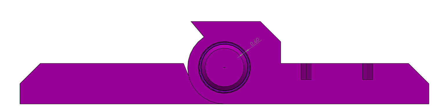
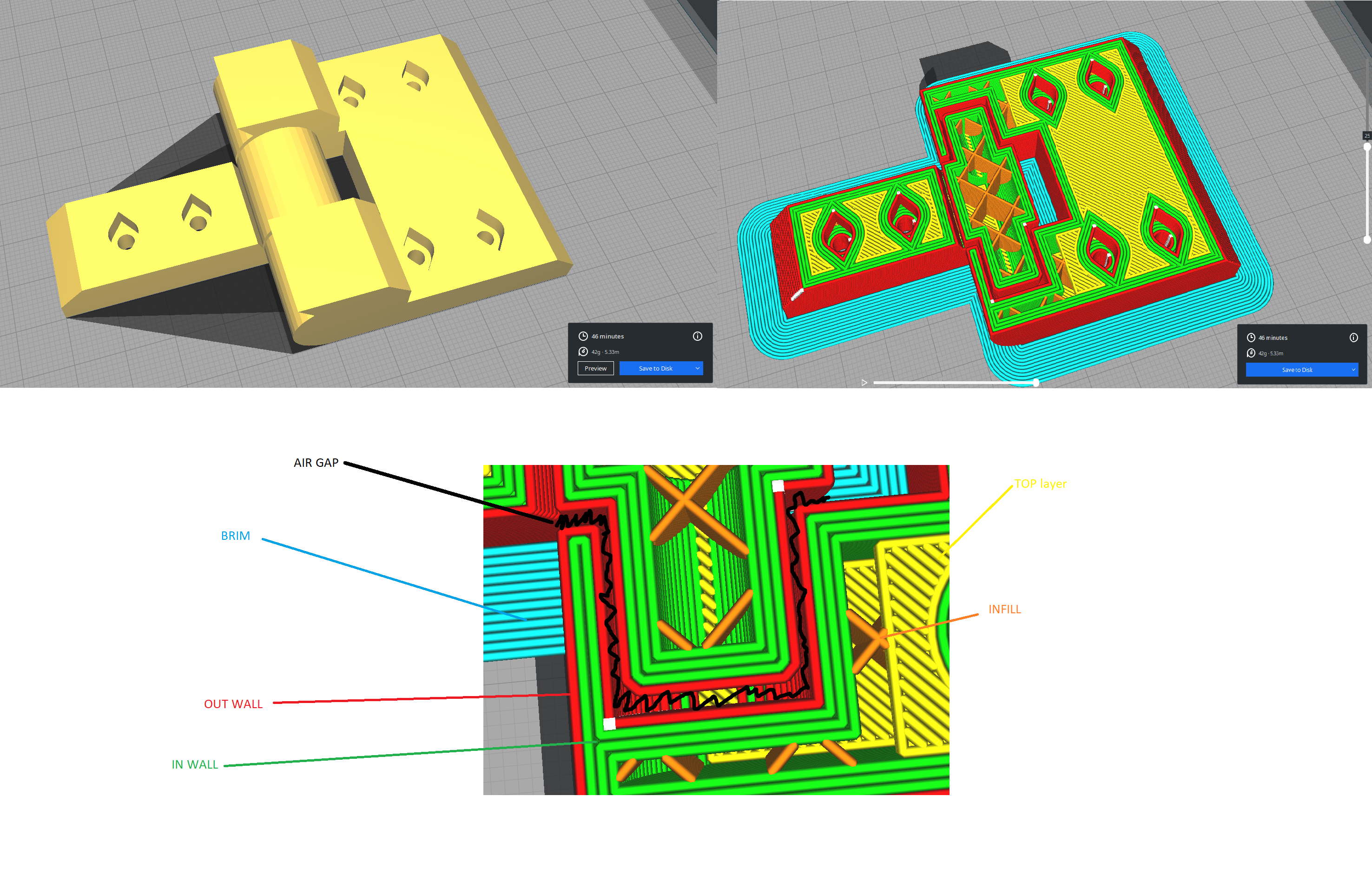
so the gap between parts looks like this

due to the heat dilation and contractrion of every materials the plastic should shrink as it gets cooler.

however if you print a little bit slower it will jam

if you print a little bit to print a little hotter than normal i'll jam

if you run the print to fast will underextrude.

it's just to irregular and odd to keep changing the parameters with every print.

and is better practice to print the files separatly

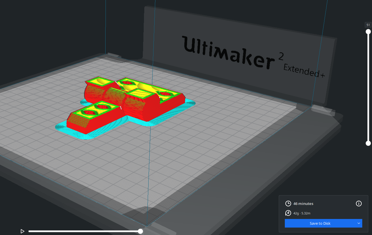
in this case the assgnment wouldn't met requirements if printed separatedly.

so i had to print a knickknack :(

cura file .3mf

g code for ultimaker 2+ extended


parameters

there are just way to many parameters that afect a 3d print.

ussually i never recomend print a mechanism in one go.

it's inefficient. it's harder to get it right.

and the result usually end up in the garbage anyways

so it's just a waste of time of the machine and effort designin something that's only will flex 3 times and will end up breaking. and is harder to replicate.

Buuuuuuuuut.....

LAYER HEIGHT settings should never be equal to the nozzle diemeter.

the maximum i recomend is 90% of the nozzle

same goes with LINEWIDTH not over 90%

print speed may vary depending on a lot of factors. but usually 60mm/s is a sweet spot for a lot of machines with 0.4mm nozzle.

then for the WALLS may vary depending on the application if it a piece that does not work mechanicaly at all 3 wall even 2 walls are enough.

but if the piece is a lever a gear or a hinge or something with a lot of stresses the minimum walls should be 4 to completly fill the piece

the same goes with INFILL settings if it just have stetic purpouses this may not be as important and you could lower it down to 5%.

but if it will get some stress you should crank it up to 100%

the use of support material. it kind of a big nono when 3d pinting.

it's just an awfull job to design just for the mere act of using a CAD software an not have in consideration the machine while drawring some sketch.

if you take into the design the fabrication process the final product will be more efficient in time and resources to make and to recycle.

the support material it's just a bunch of plastic that allows the machine to be printing in between 2 parts of the same piece without printing in mid air.


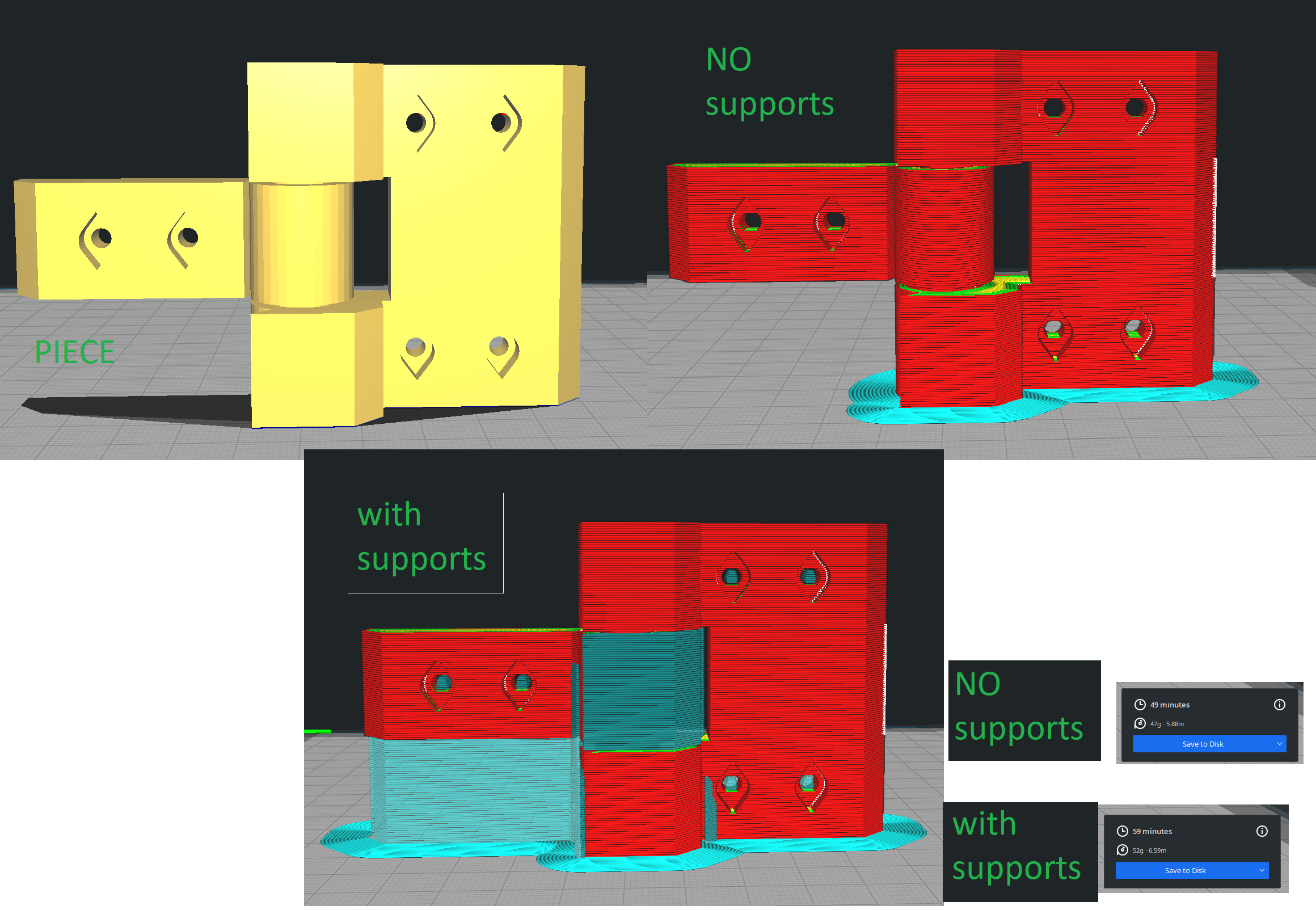
this is the diference in the same piece with supports and without supports.


another boring feature that i usually add on my designs it a teardrop shape in every bolt or shaft hole

this is just because if a change my mind with the printbed layout i technically could print in other orientation and don't have to print supports.


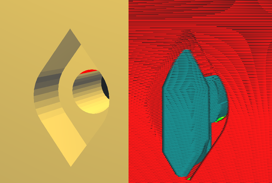
this is the diference between with and without support settings.

usually the hole in for the body of the bolt is small enough to get away with it and skip the supports but the head of the screw will almost always will need a teardrop shape.

error 404

Print

final test

Back to index

links and references


HERE you can download all of the files (solidowks native,stl,g-code for ultimaker)from the tweezer

HERE you can download all of the files (solidowks native,stl,g-code for ultimaker)from the Festos's bootleg

HERE you can download all of the skanect


here you can watch the video i was talking about the model he build