3D printing is not as simple as pressing the print button and waiting for the model to be printed. It is crucial to know how to prepare a 3D model, how the printer works and what are its limits, and how to balance printing time with print quality. This week, I'm going to test a printer, scan and print something.
3D scanning and printing
Table of content
Printing a test file
Oloid shape
3D scanning
Printing a test file ●
For this week's group assignement, I teamed up with Tue and David. We picked a test file from Thingiverse in order to test different features of one of the 3D printers we have in Fab Lab Barcelona, the Creality3D CR-10 S5 3D.
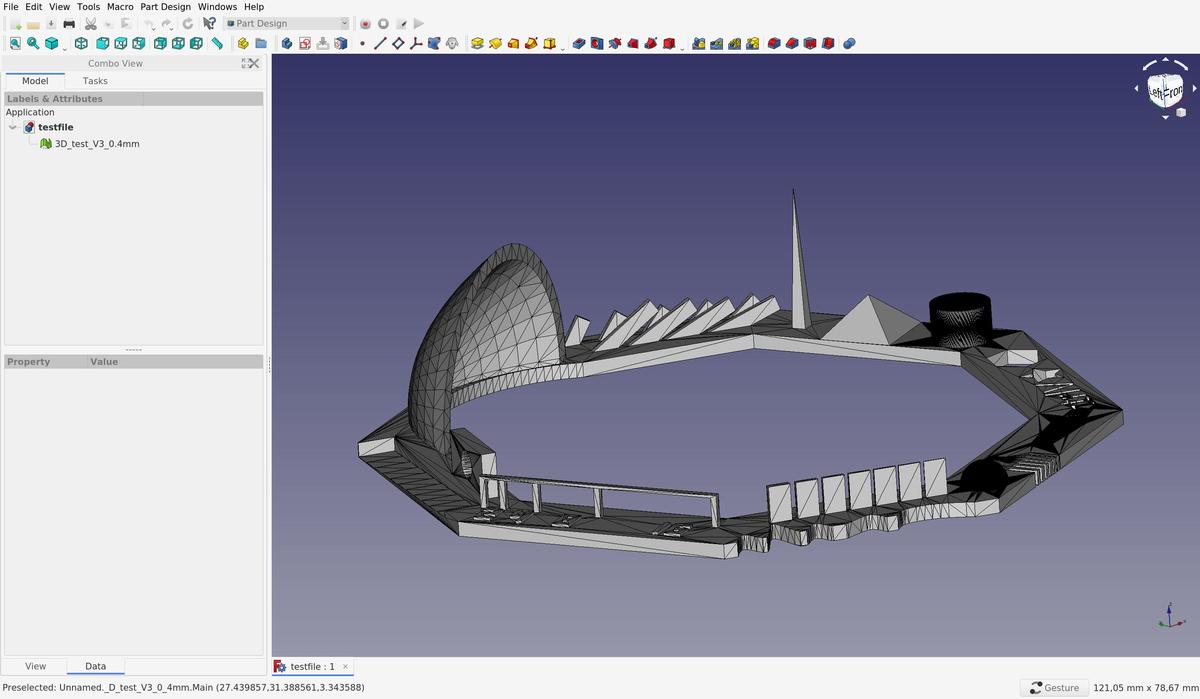
This file allows us to test these features:
- z-height check
- warp check
- spike
- hole in wall
- raft test
- overhang Steps 50° - 70°
- 2 different extrusion widths: 0.48mm & 0.4mm
Slicing
To be able to print a 3D model, we have to send instructions to the printer, wich are written in g-code and tells the motors where to move. To prepare the g-code, we have to slice our 3D model (.STL), to simulate and anticipate how the model will be printed, according to the printer settings and gravity law.
At Fab Lab Barcelona, a computer with Ultimaker Cura is attached to the machines, with all the presets of the differents printers saved in it. It's therefore easier to directly use it in order to slice our model instead of searching the presets and install them on our personal laptop.
Specific settings that we had to specify
- layer height:
0.25mm - Wall thickness:
0.8mm(= 2 lines) - Infill:
10% - Print speed:
60mm/s(= maximum for this printer)
Printing
The filament we use is a PLA 1.75mm. It's a plant-based material made from starches like soybeans or corn. It needs to be heated at 190-200C° to be used.
The printing was done in ~90 minutes without any troubles.
Results
As we can see in the images above, the definition of the print is quite good, the details are respected and the print angles can be large (in fact more than 45°). Even the small bridges without support were printed correctly. I am very satisfied with this test and the new possibilities that it lets us see.
Oloid shape ●
I'm exploring different types of shapes that could eventually be interesting regarding my final project. One of these is the oloid.
An oloid is a three-dimensional curved geometric object that was discovered by Paul Schatz in 1929. It is the convex hull of a skeletal frame made by placing two linked congruent circles in perpendicular planes, so that the center of each circle lies on the edge of the other circle. The distance between the circle centers equals the radius of the circles. One third of each circle's perimeter lies inside the convex hull, so the same shape may be also formed as the convex hull of the two remaining circular arcs each spanning an angle of 4π/3.
An oloid is a geometric shape that only has one side. That means that if you make it roll on a flat surface, its entire surface will touch the flat surface at some point.
The oloid shape can only be achieved by using an additive technique, such as 3D printing, and not a subtractive technique, such as laser cutting or milling, because the shape itself must be worked in all directions, not just from bottom to top (or by using another machine, a robot, with more axes, but then the technique begins to be too complex for a small piece like this one).
Modeling
OpenSCAD, the 3D CAD modeller that we use by writing code (as I said here) has a function called hull() that displays the convex hull of child nodes.
This is why I to use OpenSCAD to model this particular shape instead of another more conventional tool like FreeCAD.
$fn = 180; // resolution
radius = 20;

hull() {
  cylinder(r=radius, h=0.1, center=true);
  rotate(a=90, v=[1,0,0]) {
    translate([radius,0,0]) {
      cylinder(r=radius, h=0.1, center=true);
    }
  }
}
Here is the code I wrote to model the oloid. It's simple isn't it?
Slicing
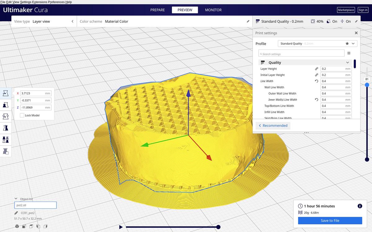
The slicing process of the oloid model was very interesting because I had to add supports to keep the shape in place during printing. It helped me understand how supports work and how to generate them in a slicer software, which is actually super easy.
To do so, I used Ultimaker Cura and its pre-configured Support options. In order to reduce the printing time and because I knew it from my previous test, I increased the overhang angle to 55° (instead of 45°).
Here is the .std file I made for printing: oloid.stl
Printing
Printing this oloid was'nt as easy as the first test I did. My first attempt failed and I had to stop printing. It gave something like this:
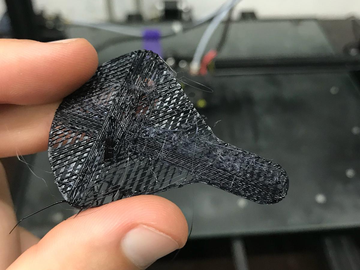
I had to call one of my instructors, Mikel Llobera Guelbenzu, to find out what had happened. But even with him, we didn't know directly where this failure came from. We had to search together, and it was very beneficial for my learning.
At first we thought it came from the amount of material coming from the extruder, as if there was a knot in the spool of filament. There was one, but after another test, it turned out that this wasn't the main problem.
Finally, Mikel discovered that the bed wasn't flat due to a wrong manipulation on previous prints. We recalibrated it and relaunched the print, and yes: it went well!
The very end of the printing was a bit problematic too. The supports didn't support the model enough and everything started to move according to the movements of the printer.
At one point it really seemed like the oloid could fall. Fortunately, I was around the printer and I could hold my piece in place using my finger. That is something I will have to consider the next time I have to think about supports.
Result
The end result is quite good, even if I could have increased the quality if I had had more printing time. But let's say it's clearly sufficient for rapid prototyping.
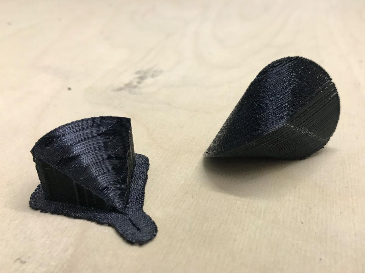
Look at this geometric beauty.
3D scanning ●
There aren't many open source tools available and maintained for 3D scanning, but Meshroom is one of them. It is an open source photogrammetry software.
Photogrammetry is the art, science and technology of obtaining reliable information about physical objects and the environment through the process of recording, measuring and interpreting photographic images and patterns of electromagnetic radiant imagery and other phenomena.
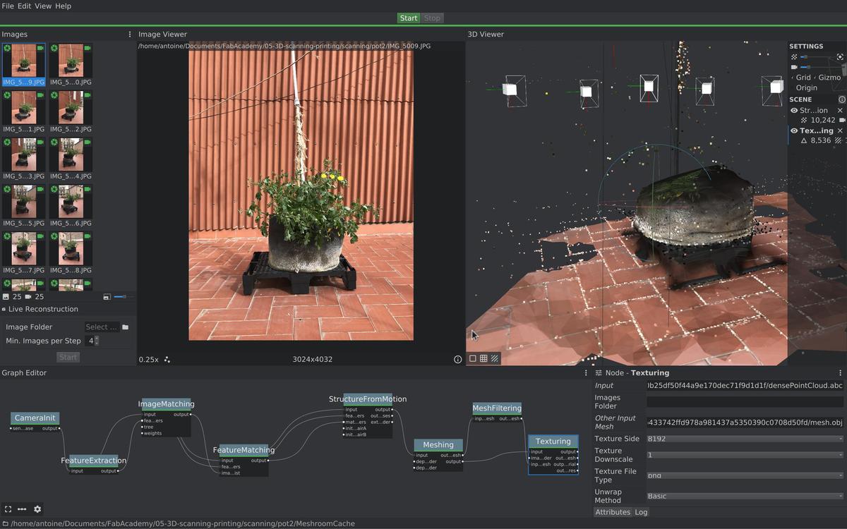
Requirements
Meshroom needs a CUDA-Enabled GPU in order to run properly. My computer doesn't have this type of processor, but I found a solution to get decent results without the full capacity of the software. I will explain it later in the process.
Installation
- Download the binary from Meshroom home page
- Unzip it in any folder.
- Open a terminal and from this folder run
./Meshroomto launch the GUI. In my case I have to type~/Documents/Apps/Meshroom-2019.2.0/./Meshroomto launch the app.
How-to
- Take pictures around the object you want to scan
- Import them into Meshroom, in drag and drop in the window.
- If you have a CUDA-Enabled GPU, simply press the
startbutton. If not, you will have to delete 3 nodes:PrepareDenseSceneDepthMapandDepthMapFilterand connect the output ofStructureFromMotionto the input ofMeshing, and finally press thestartbutton.
Problems I encountered
I had some problems getting decent results with photogrammetry. Almost all of my attempts weren't even close to a recognizable 3D scan of the object I was trying to get the shape from.
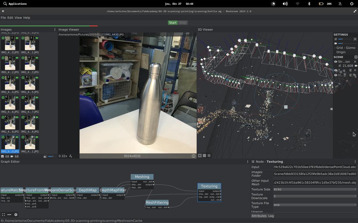
These things didn't work because the objects were either too reflective, or too small, or the light was changing from pictures to pictures, or my camera (from my phone) had a too small aperture.
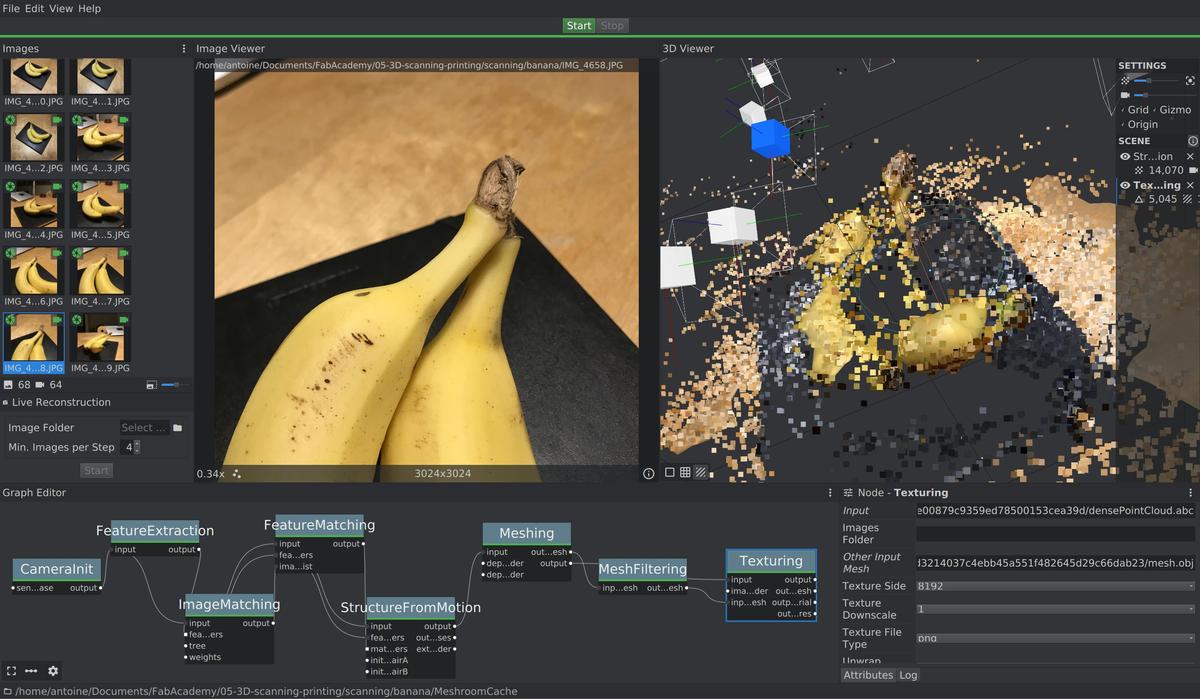
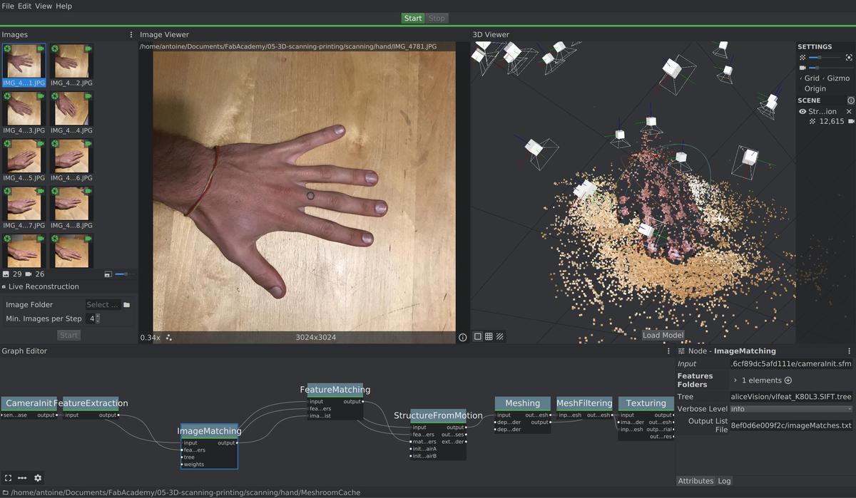
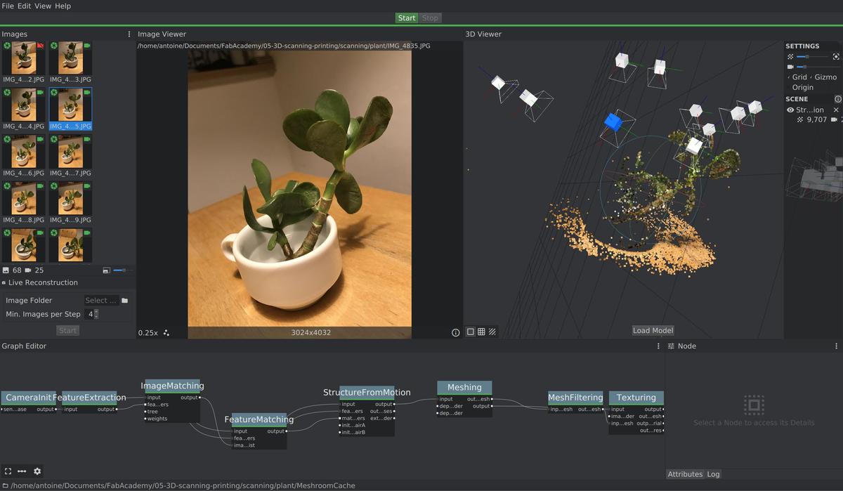
I knew that Meshroom wasn't the problem because I tried with a set of pictures validated by the community, as something that works and that can be used to test the settings of the software.
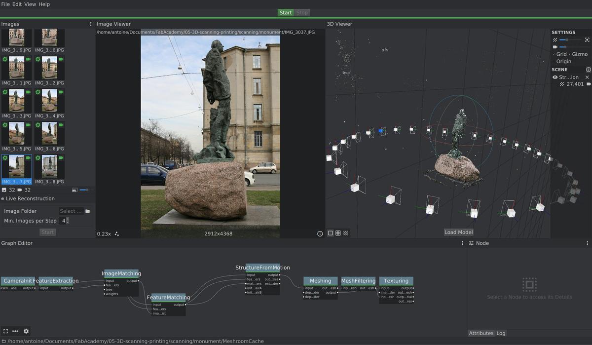
Finally, a little desperate, I went to my roof to get some fresh air and I saw this plant pot, surrounded by tiles forming a grid around the object. It looked like a last try before giving up.
And it more or less worked… I got the shape of the pot, its structure and texture. Maybe I should have taken a lot more pictures of the plant, all its leaves and its little detail to get it rendered in the final scan.
My tips for scanning an object with the photogrammetry process
- the bigger the better
- Preferably outside, with natural light
- No blurred area on the pictures, the software needs to understand the background
- A lot of pictures are needed (~70) from every angle
- Matt objects are the easiest (by far!)
Conclusion
The result is clearly worse than I imagined when thinking about photogrammetry. But it's an exploration, between cutting-edge technology and open source software driven by the community, between a beginner (me) and a very specific technique. I will have to practice taking appropriate photos for photogrammetry if I want to scan something for a real need.