4. Computer controlled cutting
This week we got introduced to parametric design and we finally got to use the lab machines! In this page I will show how I made stickers using the Vinyl Cutter and also will illustrate my steps of designing with parameters in fusion360 and cutting my design using the laser cutter.
Group Assignment
Individual Assignment
Vinyl Cutting
I used the Vinyl Cutter to make stickers for my laptop and also I made bigger wall stickers. For my laptop sticker I used my business logo in png format. For the wall stickers, I created my design using Inkscape.
Vinyl Cutter Information
| Machine Name | Software | Maximum Materials Thickness |
|---|---|---|
| Silhouette Cameo | Silhouette Studio | 2mm |
Below I show you the steps I went through when I used Silhouette Studio Software to cut in the Vinyl Cutter.
Then I prepared the machine for the job following the next steps
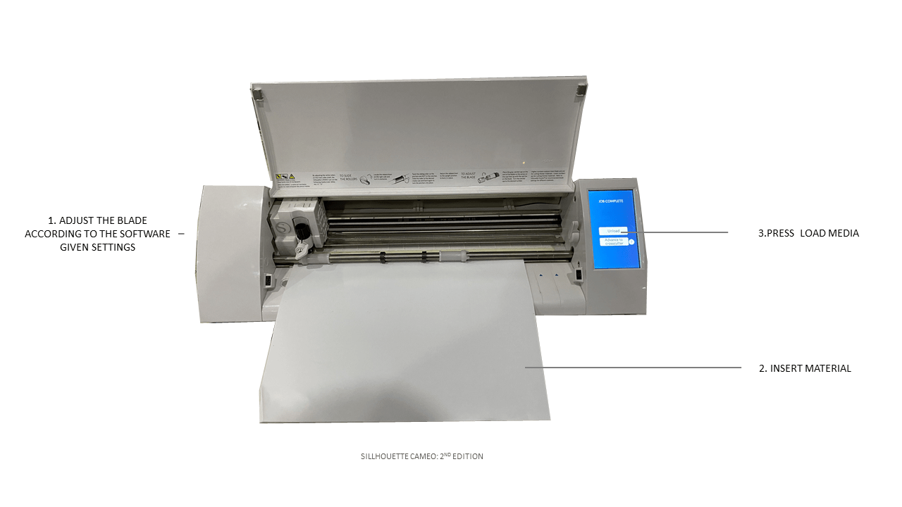
Now everything is ready to be cut !
Parametric Construction Kit
For my design I started drawing my previous shape that I extracted from the Maymooni Pattern but this time I decided to draw it from scratch instead of tracing it or inserting it as a dxf. So my steps were as follow:
1- I started from a circle, I then gave that circle a diameter measurement using parameters as shown below in the pictures.
2- Following that, I drew another 3 circles opposite to each other, and to make sure they stay in place I used “Horizontal/vertical” constraints.
3- I drew another smaller circles and gave them two constraints “Tangent” to be connected to the bigger circles, “Horizontal/Vertical” to align their centers with the other circles in one line.
4- To control the size of the smaller circles and to make sure they are all changing proportionally when changing the bigger circles, I gave their diameter a parameter of the original diameter/2.
5- I trimmed the parts I don’t need to create the desired shape.
6- To check everything was parametric I tried changing the measurement of the diameter and everything was changing accordingly in the correct proportion.
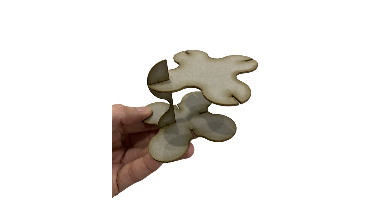
7- I created to slots the same way but by drawing lines and controlling their measurements parametrically. I also used some constraints like “perpendicular” constraints and “coincident” to make sure my slot is touching the edges of my shape and my lines are always perpendicular.
Test Cut
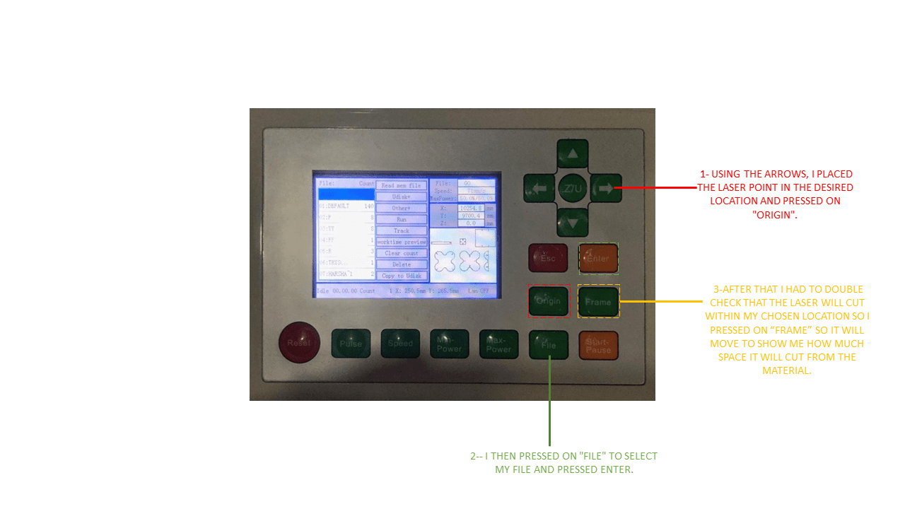
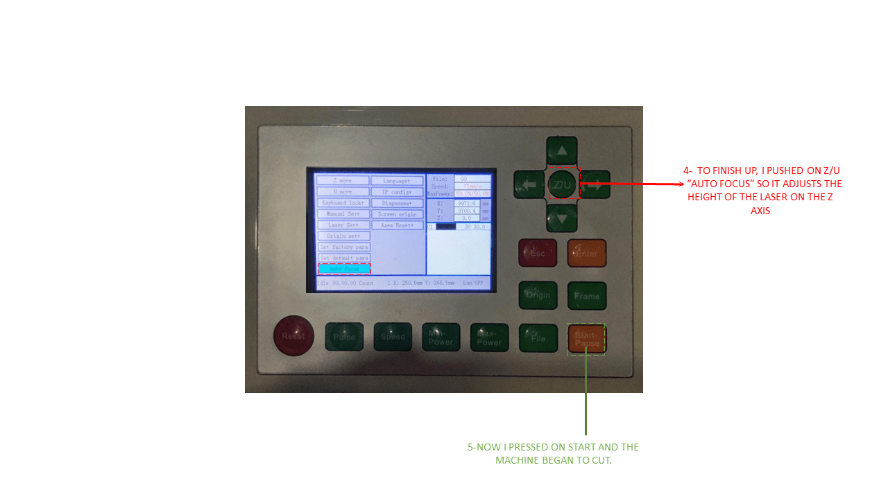
I saved my sketch from fusion360 as dxf. I then opened the printer driver in the computer in which it was installed and opened my file to run a test cut before cutting a number of pieces. The settings of the test was as shown in the picture
- Note: While cutting it is recommended to stay further back from machine because of the smoke. Also after the machine stops, you should not open the cover immediately until the smoke is gone.
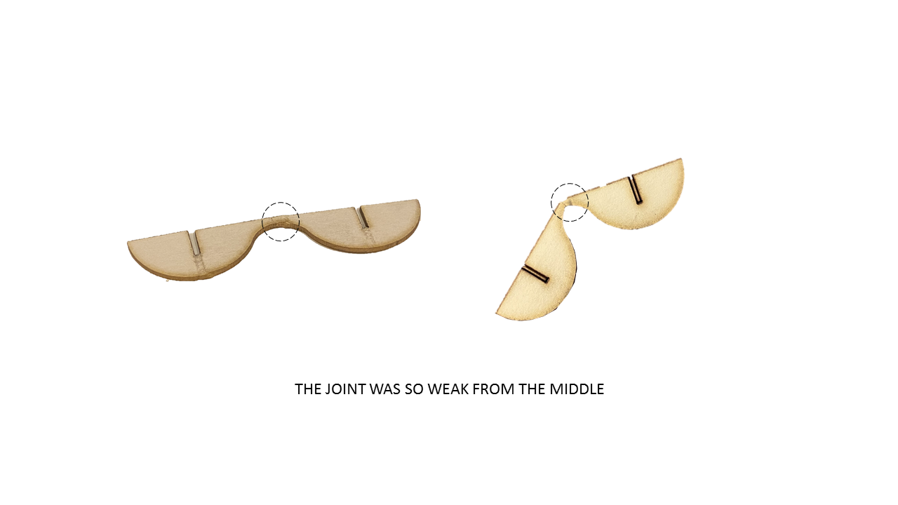
Here is the result of my first test
MISTAKES!
I then went ahead to cut the rest of my pieces however I decided to increase the power. Then that happened !
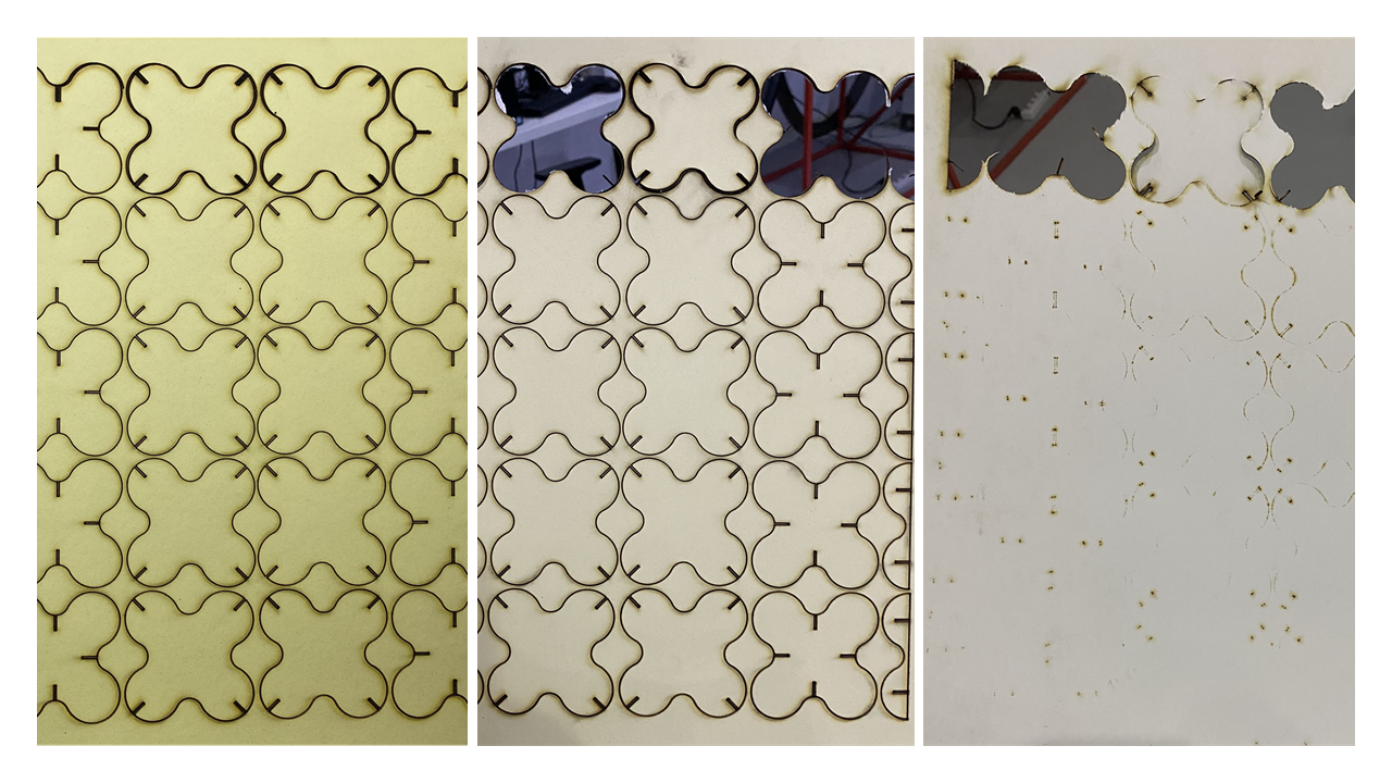
Clearly it wasn’t a good idea !
I believe something went wrong with the auto focus sensor. But for now this is what I managed to do as a results
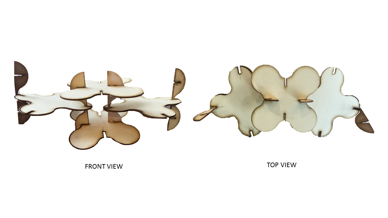
I will show my next attempt later …